Transcription
TOTEM LAKE CONNECTOR45Appendix C Basis of cuments/03 Project Documents/06 Reports/Type Size Location/A088367-REP-001-TSL 0.docx
City of KirklandTotem Lake Non-MotorizedBridge - Basis of Design2016 December 09Our Ref: A088367Prepared by:Kali Dickerson, PEReviewed by:Schaun Valdovinos, PECOWI NORTH AMERICA, INC.1191 2nd Avenue, Suite 1110Seattle, WA 98101Tel: (206) 748-4022 Fax: (206) 588-2739Website: 367/Documents/03 Project Documents/06 Reports/Basis ofDesign/A088367-R-001 BasisOfDesign rev2.docxAppendix C
Appendix C
Revision Record SheetRev.NoDateChanges ImplementedOriginatedByVerifiedByApprovedByTotem Lake Non-Motorized Bridge Basis of DesignAppendix C
Amendments Record SheetiiTotem Lake Non-Motorized Bridge Basis of DesignA0883672016 December 09Appendix C
Executive SummaryThe document prescribes the design standards and methodology to be used in the design of theTotem Lake Connector Bridge project. It provides an explanation of the design approach andlists the hierarchy of relevant codes and guidelines.Key topics included in this document include: Bridge Geometry, Design Loads, DeflectionCriteria, Vibration Criteria, Geotechnical Considerations, and Analysis.Totem Lake Non-Motorized Bridge Basis of DesignAppendix C
Appendix C
Table of Contents1Introduction . 11.11.21.32Bridge Geometry . 32.12.22.32.42.52.62.72.82.92.102.113Design Codes . 1Design Life . 2Materials . 2Deck Width . 3Alignment Geometrics . 3Clearance Requirements . 3Vehicle Stopping Sight Distance . 3Railings. 3Throw Barrier . 4Stairs and Elevators. 4Drainage . 4Expansion Joints . 4Utilities and Technology. 4Lighting . 5Design Loads . 73.13.23.33.43.53.63.73.83.9Vehicular Collision Load (CT) . 7Dead Loads (DC) . 8Pedestrian Loads (PL) . 8Vehicle Load (LL) . 8Equestrian Load (LL) . 9Wind Load (WS) . 9Earthquake Load (EQ) . 9Temperature (TU, TG) .10Load Combinations .103.9.1 Strength IA .103.9.2 Strength IB .103.9.3 Strength III .113.9.4 Extreme I .113.9.5 Extreme II .113.9.6 Service I .113.9.7 Service III .113.9.8 Fatigue I .114Deflection Criteria .125Vibration Criteria .135.1SETRA Determination of Bridge Class .13Totem Lake Non-Motorized Bridge Basis of DesigniAppendix C
5.25.36Foundation Considerations.166.16.26.36.46.57Abutments .16Approach Slabs .16South Approach .16Foundation Types .16Drilled Shafts .16Analysis .187.17.27.37.47.5iiFootbridge Class .14Comfort Level .14Global Models.18Local Models .19Foundations Models .19Pushover Analysis .20Substructure Analysis .20Totem Lake Non-Motorized Bridge - Basisof DesignAppendix C
1IntroductionThe following criteria are proposed for the design of the non-motorized bridge to beconstructed to carry the Cross Kirkland Corridor (CKC) trail over NE 124th St. and124th Ave NE (Totem Lake Blvd NE). This Basis of Design document is subject torevision and additions as preliminary design proceeds and input is received.1.1Design CodesThe standards to be used in the bridge design are listed below in order ofprecedence. This encompasses the design of the bridge control line, superstructure,substructure, foundations, abutments, railings, bearings, seismic performance, andvibration criteria.i.AASHTO LRFD Guide Specifications for the Design of Pedestrian Bridges, 2009(AASHTO Ped)ii. Service d'Etudes Techniques des Routes et Autoroutes, Footbridges –Assessment of Vibrational Behaviour of Footbridges under Pedestrian Loading –Practical Guidelines, 2006 (SETRA)iii. AASHTO Guide Specifications for LRFD Seismic Bridge Design, 2nd Edition,2011 (AASHTO Seismic)iv. AASHTO LRFD Bridge Design Specifications, 7th Edition, 2014 (AASHTOLRFD)v. AASHTO LRFD Specifications for Structural Supports for Highway Signs,Luminaires, and Traffic Signals, First Edition, 2015 (AASHTO Signs)vi. Washington State Department of Transportation Bridge Design Manual (LRFD),2016 (BDM)vii. American Institute of Steel Construction, Steel Construction Manual, 14th Edition,2011 (AISC)viii. American Concrete Institute 318-14, Building Code Requirements for StructuralConcrete, 2014 (ACI)ix. AASHTO Guide for the Development of Bicycle Facilities, 4th Edition, 2012(AASHTO Bike)x. ADA Standards for Accessible Design, 2010 (ADA)Totem Lake Non-Motorized Bridge - Basis of Design1Appendix C
xi. National Association of City Transportation Officials Urban Bikeway DesignGuide – 2nd Edition, 2014 (NACTO)Exceptions:1.2 AASHTO Ped states in Section 1.1 - Scope that “Pedestrian bridges with cablesupports or atypical structural systems are not specifically addressed”. It may bethe case that several provisions in this code are excessively conservative orunachievable for bridges of this type, especially regarding deflections andvibrations. In these cases, in lieu of AASHTO Ped, it is intended to use thedesign approach laid out in SETRA. AASHTO Seismic states in Section 3.1 that the guide specifications "shall betaken to apply to the design and construction of conventional bridges For nonconventional bridges, the Owner shall specify appropriate provisions, approvethem, or both."Design LifeThe design life shall be 75 years, consistent with AASHTO LRFD Section 1.2.1.3MaterialsBridge piers shall be comprised of: Painted steel, weathering steel, or reinforced concrete.Within the roadway clear zone, substructure elements shall be capable ofwithstanding vehicle collision loads unless protected by roadside barriers.Bridge superstructure material considerations shall include: Painted steel, weathering steel, and/or reinforced concrete.Miscellaneous elements shall be stainless steel, galvanized steel, aluminum, orwood.Galvanized steel over the wetlands is not allowed.Railings shall be comprised of: Painted steel, galvanized steel, stainless steel, and/or aluminum.Bearings shall be elastomeric, lead core elastomeric, pendulum, or disc bearings.2Totem Lake Non-Motorized Bridge - Basis of DesignAppendix C
2Bridge GeometryThe preliminary bridge geometry and layout criteria are described below.2.1Deck WidthA Level of Service (LOS) studies were produced as part of preliminary design. 2.2Clear deck width between railings shall be 14-ft.Alignment Geometrics Design speed for the CKC Trail is 15 mph. Minimum radius of curvature is set at 50-ft. The minimum bicycle stopping sight distance (SSD) shall be 140-ft per AASHTOBike. The maximum cross slope for pedestrian zones is limited to 2% per ADA. Maximum grade shall be prescribed as follows per ADA: 2.32.4Clearance Requirements Vertical clearance over the roadway shall be greater than 16-ft. Vertical clearance from the deck surface shall be a minimum of 10'-0". Roadway minimum horizontal clear zone to face of unprotected piers is 10-ft.Vehicle Stopping Sight Distance 2.55% (1V:20H) without landings (on inside of curve)The bridge design shall ensure vehicular stopping sight distances (SSD) aremaintained.Railings Railing height above the deck surface shall be 4'-6" to accommodate cyclists perthe BDM. The maximum opening size in the railing is limited to 5 inches. Handrails may be provided 34-38" above the walking surface.Totem Lake Non-Motorized Bridge - Basis of Design3Appendix C
2.6Throw Barrier 2.7Stairs and Elevators 2.82.9Throw barriers are not required.Stairs and/or elevators are not currently being considered. If a stairway is desiredat the south side of NE 124th St, it could be incorporated into the retained earthwall near the abutment.Drainage It is anticipated that overpass drainage will be collected at each end of roadwaysto be piped into roadway storm drains. The impervious bridge deck over theexisting impervious roadway will result in a net zero increase in stormwater to theexisting roadway drainage system. The south approach will drain into vegetation and the north ramp will drain intothe parkland of Totem Lake.Expansion Joints Expansion joints in the travel-way shall be bicycle-safe and detailed to provide asmooth rolling surface with a skid resistant cover plate, installed such that it isrecessed and sits flush with the concrete surface. The cover plate will be fixed tothe deck on one side of the expansion joint and sit on top of an embedded plateon the other side. The detail will create a single groove gap in the travel way(rather than a raised plate). Steel edges on each side of the gap will bechamfered to minimize the bump felt by wheeled mobility users.Cover plates will be galvanized with a non-slip coating applied to the top exposedsurface, such as SlipNot. Countersunk tamper-resistant screws shall be used tosecure the cover plate.2.10Utilities and Technology Overhead power lines shall maintain sufficient clearance from bridge. 4PSE Clearances are dependent on what the clearance is being measure to.For human beings, equipment, or cranes, clearances shall meet the WACminimum approach distances.Totem Lake Non-Motorized Bridge - Basis of DesignAppendix C
2.11Seattle City Light (SCL) conductor movement envelope for the 230 kV circuitis shown by the following diagram. The clearance required from theconductor in any position to the bridge or bridge elements is 11.5’ horizontaland 16.5’ vertical. For lighting support, the clearance required is 8.0’horizontal and 8.5’ vertical to the conductor in any position. There arecurrently have no plans for upgrades or replacements to the conductors andthese clearances only apply for the area above the CKC because as youmove further north, the movement envelope gets bigger. Underground utility impacts will be avoided where possible, or rerouted ifnecessary. Four (4) RPVC conduits 2" diameter will be included within the superstructure forfuture utilities. All pathway striping and symbols shall use high quality reflective paint. Userdelineation is to be determined.Lighting Low level uniform lighting (5 lux or 0.5 foot-candles, TBC) will be provided alongthe bridge between at-grade tie-in points with the CKC trail at each end. Thelighting system shall be tamper resistant, but readily accessible by maintenancecrews. A lighting study will be carried out in Phase 2 to demonstrate desired lightinglevels are achieved across the bridge, ramps, and along at-grade pathways. Glare from the lighting will be minimized over the roadways, with minimal lightpollution over the wetlands.Totem Lake Non-Motorized Bridge - Basis of Design5Appendix C
6Accent lighting will be explored in Phase 2 with importance stressed on schemesand colors that do not cause drivers to become distracted or that interfere withthe traffic signals at this busy intersection.Totem Lake Non-Motorized Bridge - Basis of DesignAppendix C
3Design LoadsThe applicable loads are based on Table 3.4.1-1 of AASHTO LRFD as modified perAASHTO Ped as follows:3.1 CR force effects due to creep CT vehicular collision force DC dead load of structural components and nonstructural attachments DD down drag force DW dead load of wearing surfaces and utilities EH horizontal earth pressure load EL miscellaneous locked in force effects ES earth surcharge load EV vertical pressure from dead load of earth fill EQ earthquake load LL vehicular live load LS live load surcharge PL pedestrian live loading SE force effect due to settlement SH force effects due to shrinkage TG force effect due to temperature gradient TU force effect due to uniform temperature WL wind on live load WS wind on structureVehicular Collision Load (CT) Collision loading may be considered in design where no roadside barriers areused along the roadway to offer protection to the bridge piers. The equivalenthorizontal static vehicular collision force of 600 kips will be applied five feetTotem Lake Non-Motorized Bridge - Basis of Design7Appendix C
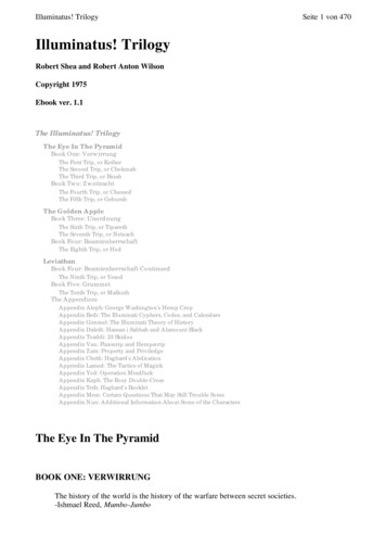
above the ground per LRFD-Spec Section 3.6.5.1. ADT/ADTT for the site will bereviewed to confirm this collision load.3.23.3Dead Loads (DC) Prestressed Concrete 165 pcf per BDM CIP Concrete 155 pcf per BDM (150 pcf per AASHTO LRFD 3.5.1) Structural Steel 490 pcf (per AASHTO LRFD 3.5.1)Pedestrian Loads (PL) 3.48Pedestrian and cyclist live load 90 psf, placed with patterns to give themaximum load effects. No dynamic load allowance is applied per AASHTO Ped. No reduction in pedestrian loading based on bridge length (this was aprevious design consideration in earlier versions of AASHTO).The design live load for pedestrian railings shall be taken as w 0.050 klf,applied simultaneously in the lateral and vertical directions, in accordance withSection 13 of AASHTO LRFD. In addition, each longitudinal element shall bedesigned for a concentrated load of 0.2 kips, acting simultaneously with the linearload at any point and in any direction at the top of the longitudinal element.Vehicle Load (LL) Demands for a water tank in tow and/or a mini-street sweeper TBC by the City. The bridge deck will be designed to accommodate an H10 two-axle vehicle inaccordance with AASHTO Ped Section 3.2. No dynamic load allowance (DLA)will be applied, and the H10 load is exclusive of PL loading. Note that this willallow for maintenance vehicles and small mechanized snow-clearing equipmentto be used on the structure.Totem Lake Non-Motorized Bridge - Basis of DesignAppendix C
Figure 1: AASHTO Ped Figure 3.2-1 – Maintenance Vehicle Configurations3.5Equestrian Load (LL) 3.6Equestrian load is not considered.Wind Load (WS) Wind loads shall be per AASHTO LRFD and modified per AASHTO Ped usingAASHTO Signs. Vertical uplift on bridge deck: 3.720 psf applied over full deck width acting at the windward quarter pointof the deck.Earthquake Load (EQ)In accordance with AASHTO Seismic, the seismic design approach for the bridge willbe based on life safety. The Response Spectrum will be constructed for the siteusing LRFD-Spec for the given Site Class as determined by the preliminary geotechrecommendations. Potential for soil liquefaction and slope movements will beconsidered per AASHTO LRFD.Totem Lake Non-Motorized Bridge - Basis of Design9Appendix C
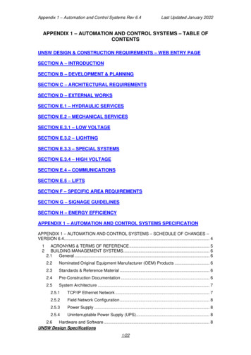
3.8Temperature (TU, TG)Uniform temperature loads due to structure temperature fall or rise are definedaccording to AASHTO LRFD.3.9Load CombinationsThe bridge will be designed for the load combinations with the load factors as shownin Figure 2 below, which is a modification of the AASHTO LRFD load table inaccordance with AASHTO Ped.Figure 2: Load Combination Table3.9.1Strength IAThis combination considers PL and LS loading but not LL.3.9.2Strength IBThis combination considers LL and LS without PL.10Totem Lake Non-Motorized Bridge - Basis of DesignAppendix C
3.9.3Strength IIIWind loading without people present on the deck in such an extreme event.3.9.4Extreme IEarthquake loading of the structure.3.9.5Extreme IIConsiders vehicle collision on any unprotected bridge piers within the clear zonefrom the roadway.3.9.6Service ICombination used to check deflections and vibrations per AASHTO Ped.3.9.7Service IIICombination used to check tensile stresses in prestressed concrete. This will not beapplicable if a steel superstructure is used.3.9.8Fatigue IFatigue loading shall be applied according to AASHTO Ped Section C3.5, whichdesignates " wind as a live load for pedestrian bridges, via the designation LL.Wind should be considered a fatigue live load for pedestrian bridges." Section C3.5further states that, "Neither the pedestrian live load nor the maintenance vehicleload is appropriate as a fatigue design loading due to the very infrequent nature ofthis loading."Therefore, in the table above, WS is assigned a load factor of 1.00 (vs 1.50) perAASHTO Ped, with no fatigue loading arising from LL or PL.Totem Lake Non-Motorized Bridge - Basis of Design11Appendix C
4Deflection CriteriaIn accordance with deflection criteria for pedestrian structures, AASHTO Ped clause5 will be checked under Service I in Table 3.4.1-1 of AASHTO LRFD. However,AASHTO Ped states in Section 1.1 - Scope that “Pedestrian bridges with cablesupports or atypical structural systems are not specifically addressed”. It may be thecase that provisions associated with the deflection criteria set out in this code areexcessively conservative or unachievable for bridges of this type.12Totem Lake Non-Motorized Bridge - Basis of DesignAppendix C
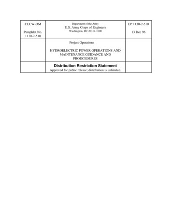
5Vibration CriteriaVibration analysis is based on AASHTO Ped, which states in Section 6: "If thefundamental frequency cannot satisfy these limitations [of a vertical frequencygreater than 3.0 Hz and lateral frequency greater than 1.3 Hz] an evaluation of thedynamic performance shall be made." The commentary of Section C6 in AASHTOPed further explains: "The technical guide published by SETRA (Service d'ÉtudesTechniques des Routes et Autoroutes) (2006) appears to present a relativelystraightforward method for addressing vibration issues when the frequencies of thebridge fall within the pacing frequencies of pedestrians." As AASHTO Ped referencesSETRA under these conditions, we will perform the vibration analysis using theSETRA method.5.1SETRA Determination of Bridge ClassThe SETRA vibration analysis method "makes it possible to limit risks of resonanceof the structure caused by pedestrian footsteps," as stated in Section 4 of SETRA.The flowchart in Figure 3 gives an overview of the SETRA methodology.Figure 3: SETRA Methodology organization chartTotem Lake Non-Motorized Bridge - Basis of Design13Appendix C
The method requires that the footbridge class and comfort level be defined, then thenatural frequency can be calculated and the appropriate acceleration range can bedetermined for the bridge. When the calculated natural frequency fits within theassigned acceleration range, the bridge design is considered to meet the vibrationcriteria.5.2Footbridge ClassThe methodology first requires a determination of footbridge Class, which "makes itpossible to determine the level of traffic [the bridge] can bear [comfortably from avibration point of view]." The footbridge classes are defined as follows: Class IV: seldom used footbridge, built to link sparsely populated areas or toensure continuity of the pedestrian footpath in motorway or express lane areas. Class III: footbridge for standard use, that may occasionally be crossed by largegroups of people but that will never be loaded throughout its bearing area. Class II: urban footbridge linking up populated areas, subjected to heavy trafficand that may occasionally be loaded throughout its bearing area. Class I: urban footbridge linking up high pedestrian density areas or that isfrequently used by dense crowds subjected to very heavy traffic.The Totem Lake Connector Bridge is designated as Class III based on projected uselevels of the CKC trail. Note that it is important to keep in mind that these definitionsare for comfort and have no effect on the loading used in structural design. Structuraldesign considers the bridge being fully loaded throughout its applicable bearing areaper Section 3.3.5.3Comfort LevelThe level of comfort also needs to be determined according to the following SETRAdefinitions:14 Maximum comfort: accelerations undergone by the structure are practicallyimperceptible to the users. Average comfort: accelerations undergone by the structure are merelyperceptible to the users. Minimum comfort: under loading configurations that seldom occur,accelerations undergone by the structure are perceived by the users, but do notbecome intolerable.Totem Lake Non-Motorized Bridge - Basis of DesignAppendix C
The Maximum comfort designation is most appropriate for pedestrian bridges linkingtransit centers or a stadium.There is also a psychological aspect associated with comfort. Users of a cablesupported structure (e.g., suspension bridge, cable-stayed) tend to expect moremovement compared to crossing a girder or truss bridge. The definition of comfort istherefore somewhat variable with respect to structure type. In any event, for this typeof urban bridge all concepts should meet the Minimum comfort level.Thus, we propose the bridge be designed to the Average or Minimum comfort levelbased on the concept type.Totem Lake Non-Motorized Bridge - Basis of Design15Appendix C
6Foundation Considerations6.1AbutmentsBridge abutments will form the interface between aerial structure and pathways onfill.6.2Approach SlabsApproach slabs approximately 10-ft long will be provided at the south and northabutments to ensure smooth transition on and off the bridge.6.3South ApproachFor the south approach, use of terraced vertical or battered earth walls may beexplored as a cost effective solution. Fill embankments and/or vegetated reinforcedearth slopes of 2H:1V or flatter could also be employed. Lightweight fill could beused to limit settlements, or the main bridge could be extended to reduce fill height ifpoor subsurface conditions are discovered.6.4Foundation TypesThe main superstructure support will be provided on deep foundations (piles ordrilled shafts), with shallow spread footings possible south of Totem Lake Blvd.6.5Drilled ShaftsDrilled shaft design will be as follows: Single drilled shafts will be used where practical. Drilled shafts will be designed for controlling of English vs. Metric diameter sizes.Metric casing sizes will be based on WSDOT BDM Table 7.8.2-2. Plans will detailshafts for English size, and contractor will be allowed to substitute equivalentmetric sizes. Drilled shaft lengths shall be set to meet the following: Provide sufficient geotechnical axial capacity. Provide sufficient depth for lateral loads as follows: 16Per FHWA Drilled Shafts, lateral deflections at the top of the shaft shall belimited to 10% of the shaft diameter.Totem Lake Non-Motorized Bridge - Basis of DesignAppendix C
For a given loading, the minimum shaft depth will be set so that the top ofshaft deflection is not sensitive to or significantly influenced by the depthof the shaft. The shaft depth vs. deflection curve shall be examined toensure the shaft depth is at or below the point at which the curve beginsto flatten; i.e., the depth at which the top defection is significantlyinfluenced by the depth of the shaft. A tip of shaft deflection less that ½-inch will be targeted for the designseismic event. Drilled shaft concrete cover and clearances will be based on WSDOT BDMTable 7.8.2‐2. Rebar spacing limits will be in accordance with WSDOT BDM requirements. Drilled shaft demand will be controlled by plastic hinging in the columns. Flexuraland shear capacity will be checked based on the following: For flexural and shear capacity calculations, concrete strength 0.85 f’c Flexural capacity check as follows: Mne 1.25 Mpo SPColumn shall be used to determine Mne using expected properties perAASHTO Seismic Table 8.4.2-1 as modified by WSDOT BDM 4.2.22 ifusing ASTM A706 Gr. 80 reinforcing. Flexural capacity will be based on expected nominal capacity, Mne, anddetermined based on a moment curvature analysis. Mpo maximum moment demand based on column plastic hinging withoverstrength factor. Additional 1.25 factor applied to Mpo is per AASHTO Seismic Section 8.9.Shear capacity check as follows: ΦsVn 1.25 Vpo Φs 0.90 Vpo maximum shear demand based on column plastic hinging withoverstrength factor. Additional 1.25 factor applied to Vpo per AASHTO Seismic Section 8.9.Totem Lake Non-Motorized Bridge - Basis of Design17Appendix C
7AnalysisThe following types of analysis will be used for design. Model descriptions areprovided in the following sections. Software (indicated in parentheses) willsupplement hand calculations and spreadsheets.(1) Global model(s): for general purpose analysis to model DL, PL, LL, Wind, EQ,etc. (CSI Bridge and/or CAMIL)(2) Local models: for detailed design of particular elements (CSI Bridge)(3) Foundation models: for determining foundation springs used in the globalmodel(s) (L-PILE)(4) Pushover analysis: to determine column displacement capacities and plastichinging loads (CSI Bridge/XTRACT)(5) Substructure: biaxial capacity (SP Column)7.1Global ModelsGlobal modelling will be as follows:18 CSI Bridge or CAMIL (COWI's in-house software with specialized capabilities forcable structures) will be used to model the structure. The bottom of columns will be modeled with an equivalent soil spring or thefoundation will be modelled with P-y soil curves through depth. Effective section properties: All elements except columns will use gross moment of inertia for all loading. Concrete piers: For vibrational analysis, the gross moment of inertia will be used, asdisplacements are small. For strength analysis, the effective (cracked) moment of inertia will beused. Effective moment of inertia for temperature load cases 0.6·Ig. Effecti
AASHTO LRFD Bridge Design Specifications, 7th Edition, 2014 (AASHTO LRFD) v. AASHTO LRFD Specifications for Structural Supports for Highway Signs, . Luminaires, and Traffic Signals, First Edition, 2015 (AASHTO Signs) vi. Washington State Department of Transportation Bridge Design Manual (LRFD), 2016 (BDM) vii. American Institute of Steel .