Transcription
Publication No. FHWA-RC-13-001November 2013Implementation of AASHTO LRFD DesignSpecifications for Driven PilesState DOT LRFDDesign Guidancefor Driven Piles
NOTICEThe contents of this report reflect the views of the authors, who are responsible for the facts andthe accuracy of the data presented herein. The contents do not necessarily reflect the policy ofthe U.S. Department of Transportation. This report does not constitute a standard, specification,or regulation. The U.S. Government does not endorse products or manufacturers. Trademarks ormanufacturers’ names appear in the document only because they are considered essential to theobjective of this document.
Technical Report Documentation Page1. Report No.2. Government Accession No.3. Recipient's Catalog No.FHWA-RC-13-0014. Title and Subtitle5. Report DateIMPLEMENTATION OF AASHTO LRFD DESIGNSPECIFICATIONS FOR DRIVEN PILES6. Performing Organization Code7. Author(s)8. Performing Organization Report No.November 2013Naser Abu-Hejleh, Ph.D., P.E.; William M. Kramer, P.E.; KhalidMohamed, P.E.; James H. Long, Ph.D., P.E.; and Mir A. Zaheer, P.E.9. Performing Organization Name and Address10. Work Unit No. (TRAIS)FHWA Resource Center (see below for address)11. Contract or Grant No.12. Sponsoring Agency Name and Address13. Type of Report and Period CoveredFederal Highway Administration Resource Center4749 Lincoln Mall Drive, Suite 600Matteson, IL 6044314. Sponsoring Agency Code15. Supplementary Notes: This report is issued by the FHWA Resource Center as a deployment aid to help highwayagencies develop LRFD-based design specifications for driven piles that explicitly cover LRFD limit states,estimated pile length and maximum supported load, drivability analysis, setup, and load tests. Also, design chartsare presented as an effective way to communicate design results. This report is intended to reinforce and supportthe design guidance provided by the AASHTO and FHWA technical references cited herein.16. Abstract. This report is intended to provide a technical resource for highway engineers responsible for thedevelopment of Load and Resistance Factor Design (LRFD) specifications for driven piles based on the 2012AASHTO LRFD Bridge Design Specifications. It addresses many of the issues and problems that highwayagencies face in implementing LRFD design for driven piles. First, the report describes the AASHTO LRFDdesign limit states for driven piles, the design information obtained by addressing these limit states, and theoverall design process needed to address them. Next, the report describes with examples the design procedurerequired to address all the strength limit states for the axial compression resistance of a single pile: geotechnical,drivability, and structural. These limit states are considered to determine the maximum factored axialcompression load that can be applied to the top of a pile, Qfmax. The geotechnical strength limit state is addressedby using both static analysis methods (e.g., the β-method) and field analysis methods (e.g., wave equationanalysis) to determine the pile nominal bearing resistance at various depths and the pile length, L, needed tosupport a given factored axial compression load applied to the top of a pile, Qf. For the field analysis methods, anew procedure to improve the agreement between the pile lengths estimated in the design and finalized in thefield is presented. The advantages of static load tests and accounting for setup are demonstrated. Drivabilityanalysis using wave equation analysis is employed to estimate the maximum length a pile can be safely driven towithout damage, Lmax. Safe drivability is addressed in the design by keeping the pile length less than or equal toLmax. The report also discusses addressing the drivability and structural limit states by fitting to local ASDpractices. The design results obtained from addressing the three strength limit states for a single pile(geotechnical, structural, drivability) include a Qf vs. depth curve and pile bearing resistance vs. depth curves upto Qfmax and Lmax. These results are summarized in a design chart that can be used by the foundation designers tooptimize and finalize LRFD design for a pile group, such as obtaining pile length and required field bearingresistance. The report presents and solves a comprehensive LRFD Design Example problem to demonstrate thedevelopment and application of design charts using static and field analysis methods. Finally, the report describeshow to ensure that all LRFD design limit states for driven piles are met in the field during construction.18. Distribution Statement17. Key Words: FHWA, AASHTO, Driven Piles, Design, LRFD,No restrictions. This document is availableASD, Pile Length, Implementation, Limit States, Strength Limittothe public from the sponsoring agency.State, Resistance, Static Analysis Methods, Dynamic AnalysisMethods, Setup, Load Test, Drivability, Wave Equation Analysis.19. Security Classif. (of this report)UnclassifiedForm DOT F 1700.7 (8-72)20. Security Classif. (of this page)Unclassified21. No. of Pages22. Price71Reproduction of completed page authorizedi
SymbolSI CONVERSION FACTORSAPPROXIMATE CONVERSIONS FROM SI UNITSWhen You KnowMultiply ByTo tydmimm2m2m2hakm2square millimeterssquare meterssquare metershectaressquare kilometers0.001610.7641.1952.470.386VOLUMEsquare inchessquare feetsquare yardsacressquare milesin2ft2yd2acmi2mllm3m3millimetersliterscubic meterscubic meters0.0340.26435.711.307MASSfluid ouncesgallonscubic feetcubic yardsfl nsozlbtons CCelsius0.0352.2021.103TEMPERATURE1.8 C 32WEIGHT DENSITYFahrenheit FkN/m3kilonewton / cubicmeterpoundforce / cubic footpcf6.36FORCE and PRESSURE or orce / square inchpoundforce / square footlbflbfpsipsf
PREFACEThis report is issued by the FHWA Resource Center as a deployment aid to help highwayagencies develop LRFD-based design specifications for driven piles that explicitly cover LRFDlimit states, estimated pile length and maximum supported load, drivability analysis, setup, andload tests. Also, design charts are presented as an effective way to communicate design results.This report is intended to reinforce and support the design guidance provided by the AASHTOand FHWA technical references cited herein.This report is intended to provide a technical resource for highway engineers responsible for thedevelopment of Load and Resistance Factor Design (LRFD) design specifications for drivenpiles based on the 2012 AASHTO LRFD Bridge Design Specifications. It addresses many of theissues and problems that highway agencies face in implementing LRFD design for driven piles,such as: (a) clarification of the AASHTO LRFD design limit states for driven piles and theoverall design process used to address them; (b) large differences between the contract pilelengths estimated in the design phase and the ordered pile lengths finalized in the field;(c) determination of the maximum factored axial compression load that can be applied to the topof a pile, Qfmax; and (d) consideration of setup in LRFD pile design. The report describes in detailthe design procedure required to address all the strength limit states for the axial compressionresistance of a single pile: geotechnical, drivability, and structural. The design results obtainedfrom addressing these three strength limit states are summarized in a design chart that can beused by the foundation designers to optimize and finalize LRFD design for a pile group, such asobtaining pile length and required field bearing resistance. A comprehensive LRFD DesignExample problem is presented and solved to demonstrate the development and application ofdesign charts using both static and field analysis methods.The materials in this report will be of immediate interest to State DOT geotechnical andstructural engineers involved in the LRFD design of driven piles and development of LRFDdesign specifications for driven piles. It will help them develop for driven piles more accurateand economical LRFD design methods than commonly used in practice. Implementation of thenew LRFD platform provides an excellent opportunity for State DOTs to change and improvetheir design practices for driven piles by implementing the design recommendations presented inthis report.The authors wish to thank Mr. Jerry A. DiMaggio (SHRP2 Implementation Manager, theNational Academies) for his technical input and reviews of an early draft of this report, and Ms.Andrea Thomas of CTC & Associates for her assistance with copyediting the final manuscript.The authors would also like to acknowledge Dr. Scott Anderson and Mr. Silas Nichols for theirtechnical reviews and continuous support of this work.iii
TABLE OF CONTENTSCHAPTER 1 – INTRODUCTION .1.1 BACKGROUND AND PURPOSE .1.2 AASHTO LRFD BRIDGE DESIGN SPECIFICATIONS FOR DRIVEN PILES1.3 FHWA LRFD IMPLEMENTATION REFERENCES FOR DRIVEN PILES .1.4 DEVELOPMENT AND ORGANIZATION OF THIS REPORT .1-11-11-11-31-4CHAPTER 2 – LRFD DESIGN LIMIT STATES AND DESIGN PROCESS FORDRIVEN PILES . 2-12.1 AASHTO LRFD DESIGN LIMIT STATES FOR BRIDGE FOUNDATIONS . 2-12.2 STRENGTH LIMIT STATES FOR AXIAL COMPRESSION RESISTANCEOF A SINGLE PILE . 2-22.2.1 Downdrag Effects and Factored Axial Compression Loads . 2-32.2.2 Geotechnical Strength Limit State . 2-42.2.3 Drivability Analysis. . 2-52.2.4 Structural Strength Limit State . 2-62.2.5 Design Chart . 2-62.3 EXTREME EVENT LIMIT STATES FOR THE AXIAL COMPRESSIONRESISTANCE OF A SINGLE PILE . 2-82.4 OTHER GEOTECHNICAL AND STRUCTURAL LIMIT STATES. . 2-92.5 CONTRACT AND ORDERED PILE LENGTHS . 2-92.6 LRFD DESIGN PROCESS FOR DRIVEN PILES . 2-102.7 LRFD DESIGN EXAMPLE PROBLEM . 2-13CHAPTER 3 – NOMINAL BEARING RESISTANCES OF A SINGLE PILE .3.1 TYPES OF PILE BEARING RESISTANCE .3.2 BEARING RESISTANCES FROM STATIC ANALYSIS METHODS .3.3 BEARING RESISTANCES FROM FIELD ANALYSIS METHODS.3.3.1 Determination of Bearing Resistances in the Field .3.3.2 Estimation of Field Bearing Resistances During Design .3-13-13-13-53-53-6CHAPTER 4 – STRUCTURAL AND DRIVABILITY STRENGTH LIMITSTATES .4.1 STRUCTURAL STRENGTH LIMIT STATE .4.2 DRIVABILITY ANALYSIS AND DETERMINATION OF Lmax .4.2.1 Governing Equations for Drivability Analysis .4.2.2 Conditions for Checking Pile Drivability .4.2.3 Wave Equation Analysis .4-14-14-24-24-34-4i
CHAPTER 5 – GEOTECHNICAL STRENGTH LIMIT STATE AND DESIGNCHARTS .5.1 GEOTECHNICAL STRENGTH LIMIT STATE .5.2 DETERMINATION OF THE MAXIMUM FACTORED AXIALCOMPRESSION LOAD (Qfmax) .5.3 SOLUTION TO THE LRFD DESIGN EXAMPLE.5.3.1 Developing a Design Chart Using the β-Method .5.3.2 Developing a Design Chart Using Wave Equation Analysis at EODConditions .5.3.3 Developing a Design Chart Using Wave Equation Analysis at BORConditions .5.3.4. Benefits of Field Verification of Setup and Conducting Static Load Tests .5.4 DEVELOPING A DESIGN CHART BASED ON FITTING TO ASDPRACTICES .5-15-15-35-35-55-75-95-105-11CHAPTER 6 – CONSTRUCTION OF DRIVEN PILES.6.1CONSTRUCTION PLAN CONTENTS .6.2APPROVAL OF THE CONTRACTOR’S PROPOSED DRIVING SYSTEM .6.3CONSTRUCTION CONTROL OF TEST AND PRODUCTION PILES .6.4COMPILATION OF DESIGN AND CONSTRUCTION DATA FORFUTURE IMPROVEMENTS .6-16-16-26-26-3CHAPTER 7 – SUMMARY .7-1REFERENCES . A-1ii
LIST OF FIGURESFigure 1.1Figure 2.1Figure 2.2Figure 2.3Figure 2.4Figure 2.5Figure 2.6Figure 3.1Figure 3.2Figure 4.1Figure 4.2Figure 5.1Figure 5.2Figure 5.3Figure 5.4Given and Required Design Information for Driven Piles .Given and Required Design Information Needed to Address the StrengthLimit States for the Axial Compression Resistances of a Single Pile .Sample Design Chart (Lmax 80 ft, Qfmax 182.6 kips) .Steps in Developing a Design Chart.ASD Design Process for Driven Piles (Hannigan et al., 2006) .Evaluating Candidate Design Methods in the Preliminary Design Phase.Details of the LRFD Design Example .LRFD Design Example: Pile Bearing Resistances from the β-Method .LRFD Design Example: Pile Bearing Resistances for Wave EquationAnalysis at EOD and BOR Conditions .LRFD Design Example: Pile Bearing Resistances for Wave EquationAnalysis Needed in Drivability Analysis .LRFD Design Example: Drivability Results from Wave EquationAnalysis .LRFD Design Example: β-Method Design Chart (Lmax 80 ft, Qfmax 235 kips) .LRFD Design Example: Design Chart for Wave Equation Analysis atEOD Conditions (Lmax 80 ft, Qfmax 182.6 kips).LRFD Design Example: Design Chart for Wave Equation Analysis atBOR Conditions (Lmax 70 ft, Qfmax 206.4 kips).LRFD Design Example: Design Chart Based on Fitting to Iowa DOTASD Design Practices Using Wave Equation Analysis at EODConditions 05-14
LIST OF TABLESTable 3.1Table 3.2Table 3.3Table 5.1Measuring Pile Bearing Resistance with Field Dynamic AnalysisMethods.Procedure for Estimating Resistances for a Field Analysis Method fromResistances Calculated with a Static Analysis Method in the DesignPhase .Developing the Median: Resistance Bias Factors Between a FieldAnalysis Method and a Static Analysis Method and Setup Factor .LRFD Design Example: Determination of Contract Pile Length withthe β-Method .iv3-53-83-95-7
LIST OF SYMBOLS AND ABBREVIATIONSNew Definitions and Notation Introduced in this Report are Provided in yGLGWLIGMinin2ksfksiAmerican Association of State Highway and Transportation OfficialsPile steel cross-sectional areaAllowable stress designBeginning of redrive (or restrike)Blows per inchDowndrag loadDepartment of transportationCombined scour depth due to local scour, contraction, and degradationscourEnd of initial pile drivingFederal Highway AdministrationFactor of safetyFoot (or feet)Square foot (or feet)Steel yield strengthGeotechnical resistance losses due to downdrag, scour, liquefaction, andfuture increases of groundwater level.Groundwater levelIntermediate geomaterialInch (or inches)Square inch (or inches)kips per square footkips per square inchPile length(length)LVertical pile penetration or depth from ground surface.LcThe contract pile length needed to address all LRFD design limit states(largest of L, Le, and Lm).LeThe pile length required to address the geotechnical extreme limit state forcompression resistance of a single pile.LmThe minimum pile length (or penetration, as in AASHTO LRFD) defined asthe deepest depth needed to address all of the applicable limit states anddesign requirements listed in AASHTO LRFD Article 10.7.6 (those notaddressed through determination of L and Le).LmaxThe maximum length a pile can be safely driven to without damage.Load and resistance factor designNumber of hammer blows needed to drive the pile 1 inch, expressed asnumber of blows per inch (bpi)LRFDNbThe pile length required to address the geotechnical strength limit state forcompression resistance of a single pile.v
NCHRPNHIPnPniQfQfmax, QfmaxandQfmax-structuralgeotechnical,Qi , γi, Rni , and φiQsQsmaxRn, Rnfield, andRnstatRndrRnreRRRR-NETTRBSuσdrσdr-maxα, αEOD, and αBORγ, γave, and γpNational Cooperative Highway Research ProgramNational Highway InstitutePile nominal axial compression structural resistance of a single pile.Nominal structural resistance available to resist the force effect (e.g., axialcompression resistance of a single pile) for a given failure mode.The largest factored axial compression load applied to the top of a singlepile in a pile group.Qfmax is the maximum factored axial compression load, Qf , that can beapplied to the top of a single pile. Qfmax is obtained as the smaller of theQfmax value determined based on the pile geotechnical capacity (Qfmaxgeotechnical) and the Qfmax value determined based on the pile structuralcapacity (Qfmax-structural).These terms appear in the general LRFD design equation (Eq. 2.2) toaddress various limit states for foundations. Qi is the force effect on thefoundation (e.g., axial compression load on a single pile) generated from aload applied to the bridge (e.g., dead load) and γi is the load factor for thatload; Rni is the nominal geotechnical resistance available to resist the forceeffect (e.g., pile bearing resistance) and φi is its resistance factors.The highest service axial compression load applied to the top of a singlepile in a pile group.The maximum service axial compression load that can be applied to the topof a single pile.Rn is the pile long-term nominal bearing (or geotechnical axial compression)resistance, defined as the smallest pile bearing resistance that would alwaysbe available to support the applied pile factored axial loads during the entiredesign life of the pile (or the bridge). Rn can be measured using fieldanalysis methods (Rn Rnfield) or estimated using static analysis methods(Rn Rnstat).Pile nominal bearing resistance available during driving and at end of initialdriving (EOD) conditions.Pile short-term nominal bearing resistance, available within a short periodof time (often few days) from end of initial driving (EOD). This resistancecan be estimated in the design phase using static analysis methods, ormeasured in the field by restriking the pile or performing a load test.Factored pile nominal bearing resistanceNet factored pile nominal bearing resistanceTransportation Research BoardSoil undrained shear strengthDriving stresses generated during pile drivingPile maximum tolerable driving stresses (pile structural resistance duringdriving)Resistance median bias factors that define the bias between a specifiedstatic analysis method and a specified field analysis method (α) at EODconditions (αEOD) and at BOR conditions (αBOR).Load factor for structural loads (γ), average load factor (γave), and loadfactor for downdrag load (γp)vi
γsatφ, φdyn, and φstatφdaφstrSoil saturated unit weightResistance factor for the method used to determine the pile nominal bearing(geotechnical axial compression) resistance. For field analysis methods(dynamic analysis methods and the static load test), φ φdyn. For staticanalysis methods, φ φstat.Resistance factor for pile drivability analysis.Resistance factor for pile axial compression structural resistance.vii
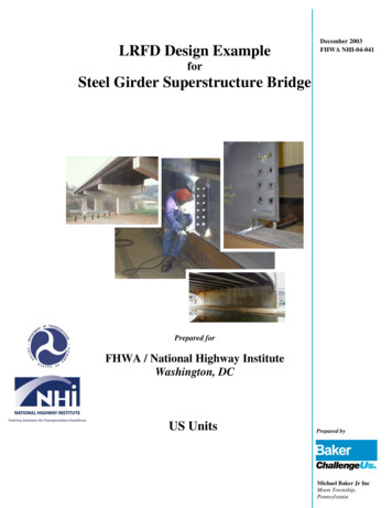
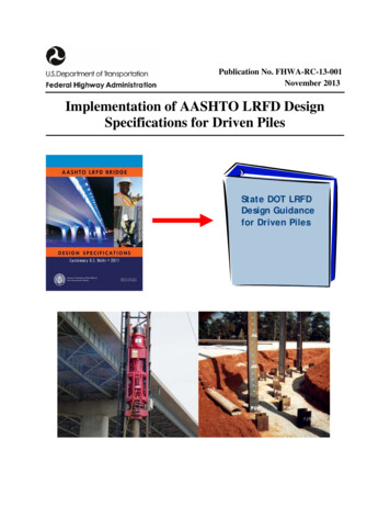
CHAPTER 1INTRODUCTION1.1BACKGROUND AND PURPOSEIn 2000, the American Association of State Highway and Transportation Officials (AASHTO)recommended, and the Federal Highway Administration (FHWA) concurred, that all Statedepartments of transportation (DOTs) should follow Load and Resistance Factor Design (LRFD)principles in the design of all new highway bridges by October 2007. The LRFD platform willreplace the allowable stress design (ASD) platform. FHWA has developed several NationalHighway Institute (NHI) training courses and LRFD-based technical manuals to assist DOTs inimplementing LRFD platform in the design of foundations, including driven piles. However,DOTs still encounter issues and problems in implementing LRFD design for driven piles.The primary goal of this report is to assist State DOTs in the development of LRFD designguidance for driven piles based on the 2012 AASHTO LRFD Bridge Design Specifications(referred to hereafter as “AASHTO LRFD”). This report addresses many of the issues andproblems that highway agencies face in implementing LRFD design for driven piles.Note that in this report, “pile length” is defined as pile penetration or depth from ground surface.1.2AASHTO LRFD BRIDGE DESIGN SPECIFICATIONS FOR DRIVEN PILESSection 10 in AASHTO LRFD (2012) presents the LRFD design specifications for bridgefoundations (spread footings, driven piles, drilled shafts, and micropiles) at the service, strength,and extreme event limit states. Foundation loads and structural and hydraulic designs aresummarized in Section 10 and described in more detail in Sections 2 to 8. Section 10 discussesthe following key topics: Article 10.4 describes the determination and selection of the soil and rock propertiesneeded for foundation design and construction.Tolerable foundation movements at the service limit state are discussed in Article 10.5.2.Resistance factors for bridge foundations at all limit states, φ, are described in Article10.5.5.Article 10.7 presents the design specifications for driven piles at all limit states. Theservice, strength, and extreme event limit states are described in Articles 10.7.2, 10.7.3,and 10.7.4 of the specifications, respectively. Figure 1.1 summarizes the main given andrequired design information for a single pile and a group of driven piles. Article 10.7.3.31-1
describes the pile length estimates needed for construction contract documents, Lc, andArticle 10.7.6 presents the limit states and design requirements needed to determine theminimum pile length, Lm (referred to as “minimum pile penetration” in AASHTOLRFD). Article 10.7.3.8 discusses two types of methods for determining the nominalbearing (or geotechnical axial compression) resistances of a single pile at the strengthlimit: static analysis methods (e.g., the β-method) and field analysis methods (e.g., waveequation analysis). In Articles 10.7.3.3 and 10.7.7, the resistances determined throughthese methods are used to estimate the pile length, L, needed to support a given factoredaxial compression load applied to the top of a single pile, Qf, at the strength limit state(see Figure 1.1). Static analysis methods (e.g., α- and β-methods; AASHTO LRFD Article10.7.3.8.6). According to the AASHTO LRFD specifications, these methods arecommonly used for estimating pile quantities in the design phase. Thespecifications indicate that static analysis may be used to finalize pile lengths inthe design phase in cases where field analysis methods are unsuitable for fieldverification of nominal pile bearing resistance. Examples include projects withsmall pile quantities or loads, sites with long setup time (e.g., soft silts or clayswhere setup is long), and when piles will be driven to hard rock (Article10.7.3.8.6a). Abu-Hejleh et al. (2010) indicated that AASHTO LRFD staticanalysis methods can be used in all cases to finalize the pile length in the designphase since reliability calibration is employed to develop resistance factors forthese methods. With these methods, site variability must be addressed (see AbuHejleh et al., 2010). Field analysis methods (AASHTO LRFD Articles 10.7.3.8.1-5). These methodsinclude the static load test and the following dynamic analysis methods: dynamictesting with signal matching, wave equation analysis, and dynamic formulas.These methods are routinely used by the vast majority of DOTs to verify pileresistances in the field and determine pile length. With these methods, the orderedpile lengths need to be determined in the field after driving test piles. In reality,contractors are often forced to order pile lengths based on the contract pile lengthsestimated in the design phase (using the pile bearing resistances obtained withstatic analysis methods) before project construction begins so as to meet rollingschedules and construction deadlines. In some cases this can lead to largedifferences between the contract and ordered pile lengths.1-2
Q fmaxLmaxGiven: Largest factored axial compression load appliedto the top of a single pile in the pile group(Q f )Given:- Soil information- Pile type/size- Loads (e.g., Q f)LRequired for pile group:- Layout: number, location, and- Contract pile length, Lc- Minimum pile length, LmRequired for a single pile:- Lmax- Q fmax- L- Bearing resistance (with field analysis methods)Figure 1.1. Given and Required Design Information for Driven Piles 1.3Article 10.7 of AASHTO LRFD discusses time-dependent changes in the nominal pilegeotechnical resistance after driving due to setup and relaxation, and also discussesgeotechnical resistance losses, GL, due to scour, future increases in the groundwater level(GWL), downdrag, and liquefaction. Site-specific setup can lead to savings if it isaccounted for in the design. However, this site-specific setup must be verified in the fieldto be fully considered in the design. Article 10.7.8 describes the drivability analysis.FHWA LRFD IMPLEMENTATION REFERENCES FOR DRIVEN PILESFHWA’s ASD-based technical references and training courses on driven piles remain valuableresources for LRFD implementation since they include materials cited in the AASHTO/FHWALRFD technical references and cover issues that did not change with the transition to the LRFDplatform. For example, the AASHTO LRFD design specifications for driven piles referfrequently to the FHWA manual on design and construction of driven piles (Hannigan et al.,2006). Although this manual follows the ASD platform, most of its contents are also applicableto the LRFD platform.1-3
To assist State DOTs in implementing the AASHTO LRFD specifications for the design ofdriven piles, FHWA developed NHI training course 132082, “LRFD for Highway BridgeSubstructures and Earth Retaining Structures,” (NHI, 2005). The course describes and givesexamples of the LRFD design of driven piles. The course has been presented to the majority ofState DOTs. FHWA has also provided direct technical support to DOTs.FHWA recently developed a new web-based NHI training course: Course 132083,“Implementation of LRFD Geotechnical Design for Bridge Foundations” (Abu-Hejleh et al.,2010). The goal of this course is to assist DOTs in the successful development of LRFD designguidance for bridge foundations based on the 2010 AASHTO LRFD Bridge DesignSpecifications and their local experience. The course first presents an LRFD implementationplan of six consecutive steps, and the remainder of the course presents recommendations to assistDOTs with implementation of these steps. The course identifies and describes significant designchanges for driven piles in the AASHTO LRFD platform compared with the ASD platform.Three options for LRFD implementation are thoroughly discussed in this course: adoptingAASHTO’s LRFD methods, or developing local LRFD design methods by fitting to ASDpractices or through reliability analysis of data collected at load test sites. Recommendations forimplementation of these three options and for development of LRFD design guidance for bridgefoundations are provided.1.4DEVELOPMENT AND ORGANIZATION
AASHTO LRFD Bridge Design Specifications. It addresses many of the issues and problems that highway agencies face in implementing design LRFD for driven piles. First, the report describes the AASHTO LRFD design limit states for driven piles, the design information obtained by these limit states, and the addressing