Transcription
Maintenance Manual MM-0637 PreSet by Meritor Hub Assemblies forTrailer Axles, and Steer and Drive AxlesRevised 07-12
Service NotesAbout This ManualThis manual provides maintenance and service procedures forPreSet by Meritor hub assemblies.Before You Begin1.Read and understand all instructions and procedures beforeyou begin to service components.2.Read and observe all Warning and Caution hazard alertmessages in this publication. They provide information that canhelp prevent serious personal injury, damage to components,or both.3.Follow your company’s maintenance and service, installation,and diagnostics guidelines.4.Use special tools when required to help avoid serious personalinjury and damage to components.If Tools and Supplies are Specified inThis ManualContact Meritor’s Commercial Vehicle Aftermarket at888-725-9355.Warranty InformationRefer to brochure SP-95155, Commercial Vehicle SystemsWarranty, for complete warranty information. For instructions toreturn warrantable parts to Meritor for reimbursementconsideration, contact Meritor’s OnTrac Technical Support Center at866-668-7221 for assistance.Hazard Alert Messages and TorqueSymbolsWARNINGA Warning alerts you to an instruction or procedure that youmust follow exactly to avoid serious personal injury anddamage to components.CAUTIONA Caution alerts you to an instruction or procedure that youmust follow exactly to avoid damage to components.@This symbol alerts you to tighten fasteners to a specified torquevalue.How to Obtain Additional Maintenance,Service and Product InformationVisit Literature on Demand at meritor.com to access and orderadditional information.Contact the OnTrac Customer Service Center at 866-668-7221(United States and Canada); 001-800-889-1834 (Mexico); or emailOnTrac@meritor.com.Information contained in this publication was in effect at the time the publication wasapproved for printing and is subject to change without notice or liability. Meritor HeavyVehicle Systems, LLC, reserves the right to revise the information presented or todiscontinue the production of parts described at any time.Meritor Maintenance Manual MM-0637 (Revised 07-12)
Contentspg. 1Section 1: Introduction2DescriptionHub AssemblyHub Pilot Wheel Mounting3Section 2: Maintenance45InspectionOil-Lubricated HubsSemi-Fluid Lubricant (Trailer Hubs Only)Check End Play7Section 3: Removal and DisassemblyRemovalHub Assembly9101214Section 4: Prepare Parts for AssemblyClean, Dry and Inspect PartsWorn or Damaged PartsGround or Polished PartsRough PartsDry Cleaned PartsPrevent Corrosion on Cleaned PartsInspection and TroubleshootingBearing Cups and ConesWheel StudsAnti-Lock Braking System (ABS) Tooth WheelSection 5: Assembly and Installation19AssemblyWheel HubInstallationWheel HubHubcapOil-Lubricated HubsGrease or Semi-Fluid Lubricant (Trailer Hubs Only)Brake Drums and Wheels21Section 6: Specifications151718Torque Specificationspg.
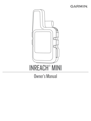
1 IntroductionDescription1 IntroductionFigure 1.3Hub AssemblyThe PreSet by Meritor hub is a low-maintenance hub assemblymanufactured for Meritor TN, TQ and TP Series trailer axles, andsteer and drive axles. The hub subassembly includes an integraltooth wheel for a vehicle equipped with an anti-lock braking system(ABS). PreSet hub assemblies also are equipped with pre-installedbearings, cups and cones, and oil seals and studs. A precisiontubular spacer between the bearings eliminates manual bearingadjustments. Figure 1.1, Figure 1.2, Figure 1.3 and Figure 1.4.4006304aSteer Axle HubFigure 1.1Figure 1.3Figure 1.4BACK VIEWCONECOVER4006300aTN Trailer HubFigure 1.14006305aFigure 1.2Drive Axle HubFigure 1.4DecalsDecals identify the type of wheel end installed. On trailers, thedecals are located on the trailer frame.Warranty4005731bTP Trailer HubFor warranty information, refer to SP-95155, Commercial VehicleSystems. To obtain this publication, refer to the Service Notes pageon the front inside cover of this manual.Figure 1.2Meritor Maintenance Manual MM-0637 (Revised 07-12)1
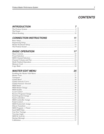
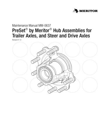
1 IntroductionHub Pilot Wheel MountingThe hub pilot wheel mounting system uses a single two-piece flangenut on each wheel stud for both single and dual wheel applications.The hub pilot wheel mounting system is also referred to as theUni-Mount-10 (10 stud), WHD-10 (10 stud), WHD-8 (8stud) and ISO system. Figure 1.5.Figure 1.5SINGLEWHEELDUALWHEEL4005733aHub PiIot Mounting SystemFigure 1.52Meritor Maintenance Manual MM-0637 (Revised 07-12)
2 MaintenanceHazard Alert Messages2 MaintenanceRead and observe all Warning and Caution hazard alert messages inthis publication. They provide information that can help preventserious personal injury, damage to components, or both.WARNINGTo prevent serious eye injury, always wear safe eye protectionwhen you perform vehicle maintenance or service.Park the vehicle on a level surface. Block the wheels toprevent the vehicle from moving. Support the vehicle withsafety stands. Do not work under a vehicle supported only byjacks. Jacks can slip and fall over. Serious personal injury anddamage to components can result.InspectionOil-Lubricated HubsActionIntervalInspect a trailer hub assembly for leakage and contaminatedlubricant.Every 12 months or 100,000 miles (160 000 km), whichever comesfirst.Inspect a tractor hub assembly for leakage and contaminatedlubricant.Every 12 months or 100,000 miles (160 000 km), whichever comesfirst.Check all threaded fasteners.After the first 1,000 miles (1609 km).Service trailer wheel hubs.Every 5 years or 500,000 miles (800 000 km), whichever comesfirst.Service tractor wheel hubs.Every 5 years or 500,000 miles (800 000 km), whichever comesfirst.Perform preventive maintenance procedures.Regularly-scheduled intervals.Perform a pre-trip inspection.Each time prior to operating the vehicle on the road.Do not mix different types of grease. Only use lubricants approvedby the original equipment manufacturer (OEM).4.Check that no oil is present on the hub, brake hardware orbrake shoes.Inspect for Leaks앫 If oil is present: Check the inboard seal.1.Wear safe eye protection.앫 If the seal is damaged, incorrectly installed or worn:Replace the seal.2.Park the vehicle on a level surface. Block the wheels to preventthe vehicle from moving. Set the parking brake.3.Check that no oil is present around the hubcap or on thewheel.앫 If oil is present: Investigate the cause and take correctiveaction.Meritor Maintenance Manual MM-0637 (Revised 07-12)3
2 MaintenanceOil ContaminationAllow any air in the oil to escape prior to inspection. Visually inspectthe lubricant for discoloration. Under normal conditions, the oil willdarken slightly. A white or milky appearance indicates watercontamination. If the inspection indicates contamination, service thewheel hub. Do not mix oil types. If you need to add oil, you must usethe same type of oil as supplied or used by the original equipmentmanufacturer.Semi-Fluid Lubricant (Trailer Hubs Only)ActionIntervalInspect the hub assembly for leakage and contaminated lubricant.Every 12 months or 100,000 miles (160 000 km), whichever comesfirst.Service wheel hubs.Every 5 years or 500,000 miles (800 000 km), whichever comesfirst.Perform preventive maintenance procedures.Regularly-scheduled intervals.Perform a pre-trip inspection.Each time prior to operating the vehicle on the road.Do not mix different types of grease. Only use lubricants approvedby the original equipment manufacturer (OEM).Table A: TP and TN Series Trailer Axles Equipped with Conventional Hub Assemblies or PreSet by Meritor Hub AssembliesLubricant Volume per Wheel EndTrailer Axle Series, Hub Assembly Type,and Hub Part Number1API-GL5 OilNLGI 00 Semi-FluidGrease2NLGI 1 or 2 Grease2TP SeriesHubcap Fill Line35.00 fl. oz. (63.16 cu. in.)NOT RECOMMENDED33.47 fl. oz. (60.41 cu. in.)23.37 fl. oz. (42.17 cu. in.)31.00 fl. oz. (55.95 cu. in.)NOT RECOMMENDED25.57 fl. oz. (46.15 cu. in.)21.22 fl. oz. (38.29 cu. in.) PreSet hub assemblyHub part number 16040Approx. 24.55 fl. oz.(44.31 cu. in.)TP SeriesHubcap Fill LineConventional hub assemblyHub part number 15968Approx. 24.55 fl. oz.(44.31 cu. in.)TN SeriesHubcap Fill Line PreSet hub assemblyHub part number 16048Approx. 15.17 fl. oz.(27.37 cu. in.)TN SeriesHubcap Fill LineConventional hub assemblyApprox. 15.17 fl. oz.(27.37 cu. in.)Hub part number 1598412The hub part number is cast into the inboard side of the wheel mounting flange.Volume includes the lubricant volume of the bearing cones. PreSet bearings are not greased prior to installation.4Meritor Maintenance Manual MM-0637 (Revised 07-12)
2 MaintenanceInspect for Leaks5.1.Wear safe eye protection.2.Park the vehicle on a level surface. Block the wheels to preventthe vehicle from moving. Set the parking brake.3.Remove the semi-fluid grease hubcap. There is no sightwindow.4.Inspect the outer bearing to verify that sufficient originalequipment manufacturer grease is present and that there is nosign of contamination.Follow the wheel manufacturer’s instructions to remove the tireand wheel assembly. Figure 2.2.Figure 2.2앫 If additional grease is required: Add grease through thefill hole (on trailer hubs only) or in the barrel of the hub, untilit flows from the outboard bearing. Do not mix grease types.Use the same grease specification installed by the originalequipment manufacturer (OEM).4003160aGrease ContaminationFigure 2.2Visually inspect the grease for discoloration. Under normalconditions the grease may darken slightly. A white or milkyappearance indicates water contamination. If the inspectionindicates contamination, service the hub.Check End Play6.Remove the hubcap. Attach the magnetic base of a dialindicator to the spindle. Touch the dial indicator stem to thehubcap mounting surface. Figure 2.3.Figure 2.3In addition to the inspection, check end play whenever the brakes ortires are serviced.1.Wear safe eye protection.2.Park the vehicle on a level surface. Block the wheels to preventthe vehicle from moving.3.Raise the axle until the tires are off the floor.4.Place safety stands under the trailer frame or under each axlespring seat. Figure 2.1.4005735aFigure 2.3Figure 2.17.Grasp two wheel studs across from each other and pull andpush the hub.4003159aFigure 2.1Meritor Maintenance Manual MM-0637 (Revised 07-12)5
2 MaintenanceWARNINGDo not retighten the spindle nut to adjust end play during theinspection procedure. This could cause bearing damage whichcan cause the wheels to loosen and separate from the vehicle.Serious personal injury and damage to components can result.8.Measure the end play by calculating the difference betweenthe minimum and maximum dial indicator readings.앫 If the end play measurement does not exceed0.006-inch (0.15 mm): No additional service is necessary.Do not adjust or retighten the spindle nut.WARNINGIf the spindle nut is loose prior to removing the PreSet hub,discard the old spacer and replace it with a new spacer beforeyou reinstall the PreSet hub. If you do not install a newspacer, the wheel bearings can become damaged, which cancause the wheels to loosen and separate from the vehicle.Serious personal injury and damage to components can result.앫 If the end play measurement exceeds 0.006-inch(0.15 mm): Service the hub. Refer to ConMet ServiceManual for PreSet Hub Assemblies. The manual can beaccessed at www.conmet.com/pdfs/preset service manual.pdf.6Meritor Maintenance Manual MM-0637 (Revised 07-12)
3 Removal and DisassemblyHazard Alert Messages3 Removal and DisassemblyFigure 3.2Read and observe all Warning and Caution hazard alert messages inthis publication. They provide information that can help preventserious personal injury, damage to components, or both.WARNINGTo prevent serious eye injury, always wear safe eye protectionwhen you perform vehicle maintenance or service.Park the vehicle on a level surface. Block the wheels toprevent the vehicle from moving. Support the vehicle withsafety stands. Do not work under a vehicle supported only byjacks. Jacks can slip and fall over. Serious personal injury anddamage to components can result.4003160aFigure 3.2RemovalWARNINGHub Assembly1.Wear safe eye protection.2.Park the vehicle on a level surface. Block the wheels to preventthe vehicle from moving. Set the parking brake.3.Raise the axle until the tires are off the floor.4.Place safety stands under the trailer frame or under each axlespring seat. Figure 3.1.Before you service a spring chamber, carefully follow themanufacturer’s instructions to compress and lock the spring tocompletely release the brake. Verify that no air pressureremains in the service chamber before you proceed. Suddenrelease of compressed air can cause serious personal injuryand damage to components.6.Figure 3.1If the axle is equipped with spring brake chambers, carefullycompress and lock the springs so that they cannot actuate.Figure 3.3.Figure 3.34003159a4003161aFigure 3.15.Remove the tire and wheel assembly, using proceduresspecified by the wheel manufacturer. Figure 3.2.Figure 3.37.For drum brake applications, remove the brake drum. Supportthe drum during the removal process to prevent damage to theaxle spindle threads.Meritor Maintenance Manual MM-0637 (Revised 07-12)7
3 Removal and Disassembly8.Place a container under the hubcap, or drive axle shaft for adrive hub, to receive the draining oil, then remove the hubcapor drive axle shaft. Do not reuse the oil. Correctly dispose of thelubricant.9.Examine the spindle nut to determine the type of lockingsystem. Follow the manufacturer’s recommended proceduresto correctly disengage the locking device.Figure 3.510. Use the following procedure to remove the PRO-TORQ nut.A.B.Remove the keeper from the PRO-TORQ nut. Use ascrewdriver to pry out the keeper arm from the groove oneach side of the nut until the keeper is released. Discardthe PRO-TORQ keeper. Do not reuse.Use a socket wrench to remove the PRO-TORQ nut.Figure 3.4.4005739aFigure 3.512. Slide the hub off the spindle. Remove and save the outerbearing cone.앫 If the hub is difficult to remove because the seal isstuck on the spindle: Use a mechanical puller to removethe hub. Figure 3.6.Figure 3.4NUTSINGLE TAB앫 If part of the seal remains on the spindle: Carefullyremove the part of the seal that remains on the spindle.Figure 3.6FLATARMSKEEPERPRO-TORQ NUT4005542aFigure 3.44005740aWARNINGDo not loosen the axle spindle nuts by either striking themdirectly with a hammer, or striking a drift or chisel placedagainst them. Damage to the parts will occur which can causepossible loss of axle wheel-end components and seriouspersonal injury.11. Remove the spindle nut system. Figure 3.5. Be careful whenyou remove the hub that you do not damage the outer bearingby dropping it on the floor.앫 If part of the seal remains on the spindle: Be careful thatyou do not damage the spindle when you remove it.8Meritor Maintenance Manual MM-0637 (Revised 07-12)Figure 3.613. Place the hub on its outboard end. Remove and discard theseal. Do not reuse the seal.
4 Prepare Parts for AssemblyHazard Alert Messages4 Prepare Parts for AssemblyRead and observe all Warning and Caution hazard alert messages inthis publication. They provide information that can help preventserious personal injury, damage to components, or both.WARNINGTo prevent serious eye injury, always wear safe eye protectionwhen you perform vehicle maintenance or service.Observe all warnings and cautions provided by the pressmanufacturer to avoid damage to components and seriouspersonal injury.Use a brass or synthetic mallet for assembly and disassemblyprocedures. Do not hit steel parts with a steel hammer. Piecesof a part can break off. Serious personal injury and damage tocomponents can result.Replace damaged or out-of-specification axle components. Donot bend, repair or recondition axle components by welding orheat-treating. A bent axle beam reduces axle strength, affectsvehicle operation and voids Meritor’s warranty. Seriouspersonal injury and damage to components can result.Solvent cleaners can be flammable, poisonous and causeburns. Examples of solvent cleaners are carbon tetrachloride,and emulsion-type and petroleum-base cleaners. Read themanufacturer’s instructions before using a solvent cleaner,then carefully follow the instructions. Also follow theprocedures below.앫 Wear safe eye protection.앫 Wear clothing that protects your skin.앫 Work in a well-ventilated area.앫 Do not use gasoline or solvents that contain gasoline.Gasoline can explode.앫 You must use hot solution tanks or alkaline solutionscorrectly. Read the manufacturer’s instructions beforeusing hot solution tanks and alkaline solutions. Thencarefully follow the instructions.CAUTIONDo not use hot solution tanks or water and alkaline solutions toclean ground or polished parts. Damage to parts can result.Clean, Dry and Inspect PartsWorn or Damaged PartsDo not repair or recondition wheel-end components. Replacedamaged, worn or out-of-specification components. Do not mill ormachine any components.Inspect the drum pilots, wheel pilots and the mounting face on thehub for damage. A damaged drum pilot is usually caused byincorrect drum mounting. A damaged wheel pilot could be the resultof incorrect wheel nut torque, which allows the wheels to slip inservice. Also, inspect the wheels and brake drum for damage.Ground or Polished Parts1.Use a cleaning solvent to clean the ground or polished partsand surfaces. Kerosene or diesel fuel can be used for thispurpose. DO NOT USE GASOLINE.2.Do NOT clean ground or polished parts in a hot solution tank orwith water, steam or alkaline solutions. These solutions willcause corrosion of the parts.3.Thoroughly clean the hub cavity with spray degreaser. Thecavity must be free of any contaminants.4.To remove grease from a wheel end, use a stiff fiber brush, notsteel, and kerosene or diesel fuel, not gasoline. Allow the partsto dry. Note that any solvent residue must be completely wipeddry since it may either dilute the grease or oil or prevent thelubricant from correctly adhering to the wheel-endcomponents.5.Clean and inspect the wheel bearings, race, spindle bearingjournals and hub. Bearings should be cleaned in a suitablenon-flammable solvent and dried with either compressed air ora lint-free rag.If compressed air is used, do not spin dry the bearings as therollers may score due to lack of lubricant. Ensure that the airline is moisture free.Rough PartsRough parts, those without smooth or machined surfaces, can becleaned with the ground or polished parts. Rough parts also can becleaned in hot solution tanks with a weak alkaline solution. Partsmust remain in the hot solution tanks until they are completelycleaned and heated.Meritor Maintenance Manual MM-0637 (Revised 07-12)9
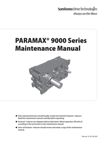
4 Prepare Parts for AssemblyDry Cleaned Parts앫 Scored or etched rollers or racesParts must be dried immediately after cleaning. Dry parts with cleanpaper or rags, or compressed air. Do not dry bearings by spinningwith compressed air.앫 Pitting of rollers or racesPrevent Corrosion on Cleaned Parts앫 The center of the large diameter end of the rollers is wornlevel or below the outer surface. Figure 4.1.앫 Wear bands on critical surfaces앫 Rust or corrosion on critical surfacesApply a light oil to cleaned and dried parts that are not damaged andare to be immediately assembled. Use only the type of oil used bythe manufacturer. Do NOT apply oil to the brake linings or the brakedrums.앫 The radius at the large diameter end of the rollers is worn toa sharp edge. Figure 4.1.앫 There is a visible roller groove in the cup or the cone innerrace surfaces. The groove can be seen at the small or largediameter end of both parts. Figure 4.2.If the parts are to be stored, apply a good corrosion preventative toall surfaces. Do NOT apply the material to the brake linings, thebrake drums or the rotors. Store the parts inside special paper orother material that prevents corrosion.앫 There are deep cracks or breaks in the cup, cone inner raceor roller surfaces. Figure 4.2.Inspection and Troubleshooting앫 There are bright wear marks on the outer surface of theroller cage. Figure 4.3.Bearing Cups and Cones앫 There is damage on the rollers and on the surfaces of thecup and cone inner race that touch the rollers. Figure 4.4.1.Wear safe eye protection.2.Use a press to remove the bearing cup.앫 There is damage on the cup and cone inner surfaces thattouch the rollers. Figure 4.5.앫 If a press is not available: Use a large hammer and heavydrift. Do not damage the bearing or hub.Figure 4.13.Inspect the bearing cup bore for evidence of cup rotation orspun cups.WORN RADIUS앫 If cup rotation exists: Replace the hub.4.Inspect the spindle journals, hub and wheel bearings for signsof wear and damage.앫 If there is damage to either the wheel bearing or race:Replace bearings and races as a set.5.Inspect the cup, cone, rollers and cage of the wheel bearingsfor the following conditions.If any of the following conditions exist, you must replace thebearing.앫 Cracked or broken separators앫 Broken or cracked rollers앫 Flaked areas on rollers or races앫 Spalled rollers or races앫 Overheated bearings앫 Brinelled races10Meritor Maintenance Manual MM-0637 (Revised 07-12)WORN SURFACEFigure 4.11003017b
4 Prepare Parts for AssemblyFigure 4.2Figure 4.5WEARGROOVESCRACKSPALLING AND FLAKING1003021bFigure 4.51003018bFigure 4.26.Observe the following guidelines when servicing the bearings.앫 Do not clean bearing cones. Replace them.Figure 4.3앫 Use the same type fluid or grease from the originalequipment manufacturer.앫 Replace with half tolerance bearings provided by theoriginal equipment manufacturer.7.Use a press to install the bearing cup into the hub. Verify thatthe cup is fully pressed against the seat. Do not over press.Figure 4.6.WEAR MARKS1003019aFigure 4.6Figure 4.3Figure 4.4ETCHING AND PITTING1003020aFigure 4.44005742aFigure 4.6Meritor Maintenance Manual MM-0637 (Revised 07-12)11
4 Prepare Parts for AssemblyWheel StudsStud InstallationReplace all wheel studs that have damaged or distorted threads.Replace broken or bent studs, and studs that are badly corroded.Also replace the stud on each side of the damaged stud. If two ormore studs in the hub are damaged, replace all the studs in the hub.Broken studs are usually an indication of either excessive orinadequate wheel nut torque.1.Wear safe eye protection.2.Support the outboard side of the flange close to the stud holeand perpendicular to the press cylinder.WARNINGTake care that you do not damage stud threads. Studs withdamaged threads can strip or cross-thread, which will reduceclamp load, loosen studs and cause a wheel to separate fromthe vehicle. Serious personal injury and damage tocomponents can result.Replace bent, loose, broken or stripped studs. When youreplace a stripped stud, always replace the stud on each sideof the stripped stud as well. Even if the adjoining studs are notcracked, they have sustained fatigue damage, which cancause the wheels to loosen and separate from the vehicle.Serious personal injury and damage to components can result.You must correctly support the hub when you remove or installa stud. If you do not support the hub correctly, serious personalinjury and damage to components can result.CAUTIONAlways replace the studs with the same part number as thoseremoved. Damage to components can result.3.앫 If the stud head is embedded into the hub: Replace thehub.4.Stud Removal1.Wear safe eye protection.2.Place the clean hub in a shop press.3.Support the inboard side of the flange adjacent to the studhead and perpendicular to the press cylinder.4.Use a press on the threaded end of the stud to force the studout of the flange.12Meritor Maintenance Manual MM-0637 (Revised 07-12)Examine the hub flange to verify the studs are not damaged,and make sure the flange was not damaged during the studinstallation process.앫 If the flange is damaged: Replace the hub.Anti-Lock Braking System (ABS) Tooth Wheel1.Wear safe eye protection.2.Inspect the ABS tooth wheel for any damage that may haveoccurred during operation or hub removal.Do not use a hammer to remove or install studs while the hubis on bearings. A hammer can cause impact damage to thebearing raceway, which will reduce bearing life. Seriouspersonal injury and damage to components can result.Ensure that you do not damage stud threads during installationprocedures. Damaged threads will not allow the stud toprovide the required clamp to support the wheel retentionsystem. The wheels can loosen and separate from the vehicle.Serious personal injury and damage to components can result.Always replace the studs with the same part number as thoseremoved. Damage to components can result. Press the newstud all the way into the hub. Verify that the stud is fully seatedand that the stud head is not embedded into the hub.앫 If the ABS tooth wheel is damaged: Identify the causeand correct the problem. Use the following procedure toremove the damaged wheel and install a new wheel.3.Be careful while using a small pry bar or hammer to removethe wheel from the hub. It could bend and damage bothcomponents. Use a circular pattern around the wheel toremove it from the hub. Figure 4.7.
4 Prepare Parts for Assembly7.Figure 4.7Press the ABS tooth wheel onto the hub.앫 If a press is not available: Use a brass or synthetic malletto drive the tooth wheel onto the hub until it is on the hub.Use care to ensure the tooth wheel is not damaged.Figure 4.9.Figure 4.94005743aFigure 4.74.Thoroughly clean and degrease the ABS tooth wheel seat onthe hub with a nonflammable solvent.앫 If the ABS tooth wheel seat on the hub is damaged:Replace the hub.5.Place the hub into a press and place the new ABS tooth wheelonto the hub ABS tooth wheel seat.6.Center the appropriate driver over the ABS tooth wheel.Figure 4.8.4005745aFigure 4.98.Figure 4.8Inspect the ABS tooth wheel to verify that the wheel iscompletely seated on the hub.앫 If the ABS tooth wheel is not completely seated:Continue to press or drive the tooth wheel onto the hub untilit is completely seated.4005744aFigure 4.8Meritor Maintenance Manual MM-0637 (Revised 07-12)13
5 Assembly and InstallationHazard Alert Messages4.Read and observe all Warning and Caution hazard alert messages inthis publication. They provide information that can help preventserious personal injury, damage to components, or both.Lubricate the seal outer diameter and hub seal bore withwheel-end lubricant. Do not apply gasket sealant to the sealouter or inner diameter. Gasket sealant is not required.5.Position the new seal into the hub bore. Do not reuse the oldseal. Replace the seal each time the hub is removed from thespindle.6.Use a seal driver to press the wheel seal evenly into the bore.Follow the seal manufacturer’s recommended instructions.Figure 5.2.5 Assembly and InstallationWARNINGTo prevent serious eye injury, always wear safe eye protectionwhen you perform vehicle maintenance or service.Park the vehicle on a level surface. Block the wheels toprevent the vehicle from moving. Support the vehicle withsafety stands. Do not work under a vehicle supported only byjacks. Jacks can slip and fall over. Serious personal injury anddamage to components can result.Tighten fasteners to the correct torque specifications. Do notover-tighten or under-tighten fasteners, which can cause thewheels to separate from the vehicle. Serious personal injuryand damage to components can result.앫 If additional force is required: Use an appropriate sealdriver, if available, and a small mallet to install the seal. If aseal driver is not available, use a flat plate and a smallmallet to install the seal.Figure 5.2AssemblyWheel Hub1.Wear safe eye protection.2.Place the hub onto a clean work bench with the seal end UP.3.Wear gloves to lubricate the inner bearing cone with the correctlubricant. Install the cone into the inner bearing cup.Figure 5.1.4005747aFigure 5.2Figure 5.1CAUTIONVerify that the seal is installed evenly into the hub. Also verifythat the seal inner diameter and the inner bearing turn freelyto prevent damage to components.7.Verify that the seal is installed evenly into the hub. Also verifythat the seal inner diameter and the inner bearing turn freely.CAUTIONYou must lubricate the inner diameter of the seal and the sealjournal to prevent damage to components.8.4005746aFigure 5.114Meritor Maintenance Manual MM-0637 (Revised 07-12)Lubricate the inner diameter of the seal with a light film ofclean wheel-end lubricant.
5 Assembly and Installation9.Place the hub onto a clean work bench with the seal endDOWN. Install the spacer.앫 If the spacer has a tapered end: The tapered end shouldface TOWARD the outboard end of the hub. Figure 5.3.12. Use a fine abrasive to remove any light corrosion fretting on thespindle. Clean and wipe with an oily rag. Cover the spindle withstandard Grade 2 grease. Both the bearing journals and theseal journal must be well-coated. In severe environments, usea Moly-grease to provide added protection.Figure 5.3InstallationWheel HubWARNINGFill the oil reservoir to the correct level. If the oil reservoir islow, damage to the bearings can result, which can cause a firein the wheel-end assembly, or the assembly can separate fromthe vehicle. Serious personal injury and damage tocomponents will result.4005748aFigure 5.310. Before installing a wheel hub, ensure that all debris has beenremoved.CAUTIONDo not support the hub on the spindle with only the innerbearing and seal. Damage to the seal can result.1.11. Lubricate the outer bearing cone with the correct wheel-endlubricant. Install the cone into the hub assembly. Figure 5.4.For drive hub installation only, place the hub horizontally andremove the outer cone and spacer. Fill the oil reservoir with asmuch oil as possible through the end of the hub with the axleflange studs. Install the spacer and outer cone into the hub.Use only lubricant approved by the component manufacturer.Figure 5.5.Figure 5.4앫 If a lubricant fill hole is avail
The hub pilot wheel mounting system uses a single two-piece flange nut on each wheel stud for both single and dual wheel applications. The hub pilot wheel mounting system is also referred to as the Uni-Mount-10 (10 stud), WHD-10 (10 stud), WHD-8 (8 stud) and ISO system. Figure 1.5. Figure 1.5 Figure 1.5 Hub PiIot Mounting System .