Transcription
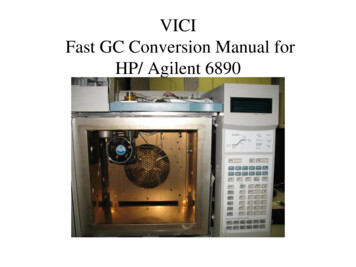
Operating ManualVolume 1. General InformationAgilent 6890 Series GasChromatograph
Agilent Technologies 2000All Rights Reserved.Reproduction, adaptation,or translation withoutpermission is prohibited,except as allowed under thecopyright laws.Part No. G1530-90447First edition, Jan 2000Replaces Part No.G153090440 Operating ManualVolume 1Printed in USASafety InformationThe 6890 GasChromatograph meets thefollowing fications: Safety Class1, Transient OvervoltageCategory II, and PollutionDegree 2.This unit has been designedand tested in accordancewith recognized safetystandards and designed foruse indoors. If theinstrument is used in amanner not specified by themanufacturer, theprotection provided by theinstrument may beimpaired. Whenever thesafety protection of the6890 has beencompromised, disconnectthe unit from all powersources and secure the unitagainst unintendedoperation.Refer servicing to qualifiedservice personnel.Substituting parts orperforming anyunauthorized modificationto the instrument mayresult in a safety hazard.Disconnect the AC powercord before removingcovers. The customershould not attempt toreplace the battery or fusesin this instrument. Thebattery contained in thisinstrument is recyclable.Safety SymbolsWarnings in the manual oron the instrument must beobserved during all phasesof operation, service, andrepair of this instrument.Failure to comply withthese precautions violatessafety standards of designand the intended use of theinstrument.Agilent Technologiesassumes no liability for thecustomer’s failure tocomply with theserequirements.WARNINGA warning calls attention toa condition or possiblesituation that could causeinjury to the user.CAUTIONA caution calls attention toa condition or possiblesituation that could damageor destroy the product orthe user’s work.See accompanyinginstructions formore information.Indicates a hotsurface.Indicateshazardousvoltages.Indicates earth(ground) terminal.Indicates radioactive hazard.Indicatesexplosion hazard.ElectromagneticcompatibilityAgilent Technologies, Inc.2850 Centerville RoadWilmington, DE 19808-1610This device complies withthe requirements ofCISPRII. Operation issubject to the following twoconditions:1. This device may notcause harmfulinterference.2. This device must acceptany interferencereceived, includinginterference that maycause undesiredoperation.If this equipment doescause harmful interferenceto radio or televisionreception, which can bedetermined by turning theequipment off and on, theuser is encouraged to tryone or more of thefollowing measures:1. Relocate the radio ortelevision antenna.2. Move the device awayfrom the radio ortelevision.3. Plug the device into adifferent electrical outlet,so that the device and theradio or television are onseparate electricalcircuits.4. Make sure that allperipheral devices arealso certified.5. Make sure thatappropriate cables areused to connect thedevice to peripheralequipment.6. Consult your equipmentdealer, AgilentTechnologies, or anexperienced technicianfor assistance.7. Changes or modificationsnot expressly approvedby Agilent Technologiescould void the user’sauthority to operate theequipment.HP is a registeredtrademark of HewlettPackard Co.Microsoft , Windows ,and Windows NT areregistered trademarks ofMicrosoft Corporation.Sound EmissionCertification forFederal Republic ofGermanySound pressure Lp 65 dB(A)During normal operationAt the operator positionAccording to ISO 7779(Type Test)When operating the 6890with cryo valve option, thesound pressure 74.6 dB(A)during cryo valve operationfor short burst pulses.SchallemissionSchalldruckpegel LP 65dB(A)Am ArbeitsplatzNormaler BetriebNach DIN 45635 T. 19(Typprüfung)Bei Betrieb des 6890 mitCryo Ventil Option tretenbeim Oeffnen des VentilsimpulsfoermigSchalldrucke Lp bis ca. 74.6dB(A) auf.
ContentsChapter 1.The 6890 Series Gas ChromatographManuals. 2Control tables. 3Using control tables . 4Some specifics . 6Gas control. 6Columns . 6Inlets and detectors .6Signals . 6Automation . 6Methods and sequences . 6Valves. 7Strategy . 8Maintenance information . 9Fuses and batteries . 9Maintenance schedule . 10General warnings. 11Many internal parts of the GC carry dangerous voltages . 11Electrostatic discharge is a threat to GC electronics. 11Many parts are dangerously hot. 12Shutting down the GC . 13For less than one week . 13For more than one week . 13Chapter 2.The Keyboard and DisplayThe display . 17The status board . 20The keyboard . 21Instant action keys [Start], [Stop], and [Prep Run] .22Function keys. 23Short-cut keys [Temp], [Pres], [Flow], [Det Control], [Ramp #] . 24[Temp], [Pres], and [Flow]. 24[Det Control]. 25[Ramp #] . 26[Info]. 27i
Contents[Status]. 28The Ready/Not Ready status table. 28The setpoint status table. 29Procedure: Configuring the setpoint status table. 29Miscellaneous keys . 30[Time] . 30Procedure: Setting time and date . 30Procedure: Using the stopwatch. 31Procedure: Setting up [Post Run] . 31[Run Log] . 32[Options] . 33[Config] . 35Modifier keys . 36[Mode/Type] . 36[Clear]. 37[Delete]. 37[.] . 38[–] . 38Storage and automation . 39Default parameters. 40Procedure: Loading the default parameters. 40Chapter 3. Flow and Pressure ControlHydrogen shutdown. 43Column shutdown . 43Turning gas flows on and off . 44EPC-controlled streams . 44NonEPC-controlled streams. 44Part 1. Electronic Pneumatic Control (EPC) . 45Interpreting flow and pressure readings . 45Configuration . 46Columns and inlets. 47Configure the column . 48Procedure: Configuring a capillary column. 49Additional notes on column configuration. 50Configure the carrier gas. 51Procedure: Configuring the carrier gas. 51Select a column mode. 52ii
ContentsThe flow modes . 52The pressure modes.52Procedure: Selecting a column mode. 53Enter the initial flow or pressure or average linear velocity . 54Procedure: Setting initial flow or pressure or average linear velocity. 56Enter a flow or pressure program (optional). 57Procedure: Programming column pressure or flow . 57Enter the rest of the inlet parameters. 59Procedure: Setting the rest of the inlet parameters. 60Detectors . 62Gas configuration. 65Makeup gas . 65Auxiliary channels .66Procedure: Changing an auxiliary channel frit. 69Maintaining EPC calibration . 70Flow sensors. 70Pressure sensors . 70Zero conditions . 70Procedure: Zeroing flow and pressure sensors. 71Part 2. NonEPC control . 72Inlets. 72Septum purge. 72Detectors . 73Internal/external plumbing: FID and NPD without EPC . 73Internal/external plumbing: TCD without EPC. 74Internal/external plumbing: ECD without EPC. 74Part 3. Measuring flow rates . 76Measuring flow rates with a bubble meter. 76Where to measure flows . 77Adapters for measuring flow rates . 77Procedure: Measuring gas flows with a bubble meter . 78Interpreting flow meter measurements . 79Part 4. Flow and pressure problems . 80A gas does not reach the setpoint pressure or flow. 80A gas exceeds the setpoint pressure or flow . 81The inlet pressure or flow fluctuates . 81The measured flow is not equal to the displayed flow . 82iii
ContentsChapter 4. The Column OvenOven capabilities . 84Oven safety. 85Configuring the oven. 86Procedure: Setting up an isothermal run . 87Making a temperature-programmed run . 88Oven temperature programming setpoints . 89Oven ramp rates. 90Procedure: Setting up a single-ramp program . 91Procedure: Setting up a multiple-ramp program . 92Fast chromatography. 93Fast-heating oven. 93Configuring the oven . 93Using the oven insert for fast chromatography. 94To install the oven insert . 94Removing the insert. 96Cryogenic operation. 97Cryogenic control setpoints . 97Chapter 5. Columns and TrapsPart 1. Capillary columns . 100Column hanger . 100Procedure: Preparing capillary columns . 101Procedure: Installing capillary columns in the split/splitless inlet . 103Procedure: Installing capillary columns in the cool on-column inlet . 105Procedure: Installing capillary columns in the purged packed inlet . 106Procedure: Installing capillary columns in the PTV inlet and Volatiles Interface . 109Procedure: Installing capillary columns in NPD and FID detectors . 109Procedure: Installing capillary columns in the TCD . 113Procedure: Installing capillary columns in the ECD and µ-ECD . 114Procedure: Installing capillary columns in the FPD . 118Ferrules for capillary columns . 121Graphite and graphitized-Vespel ferrules . 121Vespel ferrules. 121Part 2. Packed metal columns . 122Overview: installing packed metal columns . 122Fittings . 123iv
ContentsPreparing packed metal columns . 124Procedure: Making a spacer from Teflon tubing . 125Procedure: Installing ferrules on a metal column .127Procedure: Installing an adapter in a detector fitting . 128Procedure: Installing packed metal columns . 129Ferrules for packed metal columns . 130Part 3. Packed glass columns . 131Overview: Installing glass packed columns . 131Procedure: Installing glass packed columns .133Ferrules and O-rings for glass packed columns . 135Part 4. Conditioning columns . 136Procedure: Preliminary column conditioning steps . 137Procedure: Conditioning a capillary column . 138Procedure: Conditioning packed columns . 139Part 5. Conditioning chemical traps . 140Part 6. Calibrating your capillary column (optional) . 141Calibration modes .141Column calibration procedures . 142Procedure: Estimate the actual column length or diameter froman elution time. 142Procedure: Estimate the actual column length or diameter fromthe measured flow rate. 144Procedure: Estimate the actual column length and diameter . 146Chapter 6. Signal HandlingUsing the signal control tables. 150Signal type. 150Value . 150Analog output settings—zero, range, and attenuation . 154Analog zero . 154Procedure: Zeroing signal output. 154Range—for analog outputs only . 155Attenuation—for analog outputs only. 156Data rates . 157Procedure: Selecting fast peaks . 157Digital data handling . 157Digital zero. 157v
ContentsBaseline level shifts . 157ChemStation . 159INET . 160Column compensation. 160Procedure: Creating a column compensation profile . 162Procedure: Making a run using column compensation . 162Procedure: Plotting a stored column compensation profile . 164Test plot. 164Chapter 7. Instrument AutomationExecuting events during the run . 168Run time programming. 168Using run time events . 169Procedure: Programming run time events. 170The run table . 171Procedure: Adding events to the run table. 171Procedure: Editing events in the run table. 172Procedure: Deleting run time events. 172Clock time programming. 173Using clock time events. 174Procedure: Programming clock time events . 174Procedure: Adding events to the clock table . 177Procedure: Editing clock time events . 177Procedure: Deleting clock time events . 178Chapter 8. Analytical MethodsWhat is a method? . 180What can you do with it? . 180Creating a method . 181Procedure: Storing a method . 182Procedure: Loading a previously stored method. 183Procedure: Loading the default method . 184Method mismatch. 185User-entered configuration changes . 185Hardware configuration changes. 185Procedure: Modifying a previously stored method . 186Procedure: Deleting a stored method . 187vi
ContentsMethod listings. 187Chapter 9. Valve ControlThe valve box . 190Heating the valves .
90440 Operating Manual Volume 1 Printed in USA Safety Information The 6890 Gas Chromatograph meets the following IEC (International Electrotechnical Commission) classifications: Safety Class 1, Transient Overvoltage Category II, and Pollution Degree 2. This unit has been designed and tested in accordance with recognized safety