Transcription
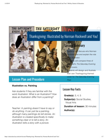
Operating Instructions for Cat. No. 6556-SCBK3 and -SCBK3DCWhat this ContainsUse these instructions to: Connect and Operate thePanelView 600 TerminalOn pageconnect and operate the PanelView 600 terminaluse typical featuresreset an alarm messageaccess screens (by password) from the Main menu– configure various functions of the control system– use Active screens to edit/monitor PLS and DM functions– use Recipe screens to create PLS and DM functions– monitor various functions of the control system12334142025Connect the PanelView 600 terminal (Cat. No. 6556-SPV600) to theLink Coupler (Cat. No. 1747-AIC) with the 1747-C20 cable.The PanelView 600 terminal is factory-set for your application.ALLEN-BRADLEYLink Coupler1747-AICPanelView 6001747-C11Chassis AacbF1F2F3F6F7F8F4F5ACommunicationPort, DH-485YB"cable thatyou makedChassis BPowerConnector1747-C20120V AC1747-C11Link Coupler1747-AICLocate and use these items on the front panel:Locator: This item:aDoes this:cpresents screens (Displayed function keys define the purpose ofhard function keys located immediately below the display area.)hardwhen pressed, initiates the function defined by one of the softfunction keys function keys displayed on the screen immediately aboveenter keywhen pressed, enters the field that you moved the cursor todcursor leysbdisplay areawhen pressed, moves the cursor in the direction of the arrow
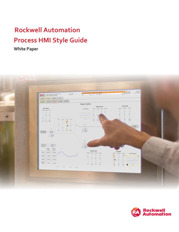
2PanelView 600Using Typical FeaturesOperating InstructionsWe illustrate typical features displayed on a PanelView 600 terminal.F1F2F3F4YF5AF6F7"BF8Using Function KeysNotice the double row of keys displayed at the bottom of the screen.The upper row of displayed keys matches hard keys [F1] – [F5], andthat the lower row of displayed keys matches hard keys [F6] – [F10].Displayed keys typically change from one screen to another.To select choices from a function displayed on the screen such as[PROD SOURCE] or to select another screen such as [TIMERS],press the hard key associated with the displayed key. For example,the [PROD SOURCE] key lets you toggle between DM channel orpress cycles as the source of a production counter.Entering a Preset [#####]To enter a preset, cursor to the datafield. When you enter a digit from thekeypad, the screen presents a numeric entry window showing valid-entrylimits. Enter a preset and press the enter key (long-arrow).Enter value(range)Scrolling Multiple Values [ 1]To scroll multiple values such as selecting a number between 1–20, cursorto the datafield and repeatedly press the up or down arrow key on keypad.Reading Machine StatusInformation indicating machine status is displayed in reverse video.For example, ACTUAL: ######## shows the accumulated count.
PanelView 600Reset an Alarm MessageOperating Instructions3Whenever the processor detects a fault condition, it displays an alarmmessage (banner) across whatever PanelView screen you are viewing.Proceed as follows to reset the alarm message and correct the condition:1. Read the message.2. Press [CLEAR] to clear the alarm message.3. To learn more about the condition(s) causing the alarm,a) Go to the Main Menu and press [ALARM HISTORY].b) Observe the list of time–stamped alarm messages.4. Take appropriate action to correct the condition(s).Otherwise, the alarm may continue to re–occur.5. To return to the previous screen, press [RETURN].Password Accessfrom the Main MenuAt power up, the PanelView 600 terminal presents the Main Menu.To gain access to security-sensitive screens, you must enter a password.To access:For this purpose:Press:Config MenuSet passwords and access configuration screens1234Active MenuEdit/monitor PLS and DM functions, online[ACTIVE MENU]Recipe MenuCreate PLS and DM functions, offline[RECIPE MENU]On the Configuration menu, we give you two levels of password access: system-level for access to the Configuration menu and screens edit-level for access to Active (online) and Recipe (offline) screensImportant: Set your 4–digit passwords (next) to establish system security.Without a password, you may access the monitor-level screens.To monitor:Press:control system functionsany other key
4PanelView 600Configuration ScreensOperating InstructionsUse the Configuration Menu to: Enter system- and edit-level passwords Configure the system for press-speed compensation (see page 13) access configuration screens
PanelView 600Operating Instructions5System ConfigurationUse this screen to configure one or more of the following options: second resolver input (to chassis B) tonnage monitor analog I/O for automatic counterbalance, shut height adjustment,and/or variable-speed drive of the press motorTo add an option, you must enable it on the System Configurationscreen and slot the associated I/O module. To enable or disable afunction, you toggle the hard function key indicated by itscorresponding soft function key at the bottom of the screen.For this option:Enable/Disable:Be sure to slot this I/O module:See wiring:2nd resolver (chassis B)RESresolver module in slot 3, chassis Bsheet 8tonnage monitor (chnls 1, 2) TON 1–2tonnage module in slot 7, chassis Asheets 12tonnage monitor (chnls 3, 4) TON 3–4tonnage module in slot 8, chassis Asheet 13counterbalanceCBanalog I/O module in slot 6, chassis Bsheets 9, 11shut heightSHsame as counterbalancevariable-speed driveSPEEDsame as counterbalanceAfter completing this screen, go to the following as needed:Press:To:[RESOLVER]configure resolver(s)6[TONNAGE]calibrate and set alarms for tonnage monitoring10[ANALOG][MAIN MENU]set sensor ranges and setpoints for counterbalance,shut height position, and variable-speed driveset variable-speed compensation, if usedOn page:1213, 4
6PanelView 600Operating InstructionsResolver ConfigurationYour C/B control requires a resolver input to chassis A. For the positioninput to chassis B, use either a second resolver or rotary cam switches.Important: If using rotary cam switches for chassis B, adjust themmechanically, independent of this screen.Important: If using a second resolver, you must enable it on the SystemConfiguration screen and configure it on this screen If not, this screenignores datafields for chassis B.To enter data, place the cursor on the datafield. Enter values on the keypad.1. Enter ON/OFF settings for the BCAM, TCAM, and ACAM.Important: For instructions, see User Manual (6556-6.5.11) chapter 3.2. Enter an angular value for TOP STOP in the range of 0–359o.The faster the press speed, the larger the back off from 359o.3. Enter a value for BRAKE-TEST ANGLE.The range is 30–90o inclusive, typically 90o.4. Enter a value for BRAKE-FAULT TIME in units of milliseconds.When doing a brake test if the stopping time exceeds value, theprocessor declares a brake-test fault. Replace or repair the brake.Before you can re-start the press, you must press the Fault Resetbutton to reset the alarm.5. Use these function keys as follows:Press this key:ZEROBRAKE TESTTo do this:Determine the shaft position that you want to call 0o.First, rotate the shaft to that position.Test brake performance.First, take appropriate safety precautions.ATTENTION: Pressing this key E-STOPS the press.
PanelView 600Operating Instructions7Lube SystemThis screen lets you apply manual lubrication, or set up automaticlubrication for these lubrication modes: continuous – lube output is on as long as the motor is running pulsed (timed intervals) – lube output goes off for a preset numberof minutes, then pulses a preset number of times (then repeats) pulsed (press cycles) – lube output goes off for a preset number ofpress cycles, then pulses a preset number of times (then repeats)You select the lubrication mode from the screen’s selection window.The module is designed to stop the press when it detects the absenceof lube pressure during pulsed or continuous operation. For pulsed lube, you preset the pulse on and off times. You alsopreset a time delay to obtain full pressure with each pulse beforethe module tests for lube pressure. For continuous lube, lube output remains ON regardless of adetected low-pressure fault that stops the press.Notice the separate setup for inch and other press control modes.Press this key:To do this:MANUAL LUBEapply lubrication manuallyCONT/PULSEselect either continuous or pulsed lube mode
8PanelView 600Operating InstructionsProduction CountersThis screen compares the actual production count with a preset total, andlets you select the count source and action to be taken at completion for: production – total number of parts for the job batch – number of parts to fill the binThe screen presents two rows of function keys, one row for production,the other for batch. The functions are similar for both.Enter a preset for total count in the SETPOINT data field.Then, toggle function keys to select choices and enter values:Press this key:To do this:SOURCEtoggle between a DM channel (also select the channel number)or press cycles (the processor counts each cycle)ON / OFFtoggle between the counter turned OFF or ONRESETreset the SETPOINT value to zeroTOP-STOP/WARNING(for production)toggle OUTPUT action at completionbetween WARNING and TOP-STOPAUTO/MANUAL(for batch)toggle OUTPUT action at completion between:MANUAL: The processor top-stops the press and sets an output.The operator must:– replace the bin– press the Fault Reset button– re-start the press.AUTO:The press continues, but an output (slot 5B) is set to initiateautomation such as replace the bin. Automation must turnauto-batch input ON (slot 2A) which turns OFF the output.Count information is not stored with the indicated part file.Important: The indicated count depends on when the operator reset thecounter. The count could indicate total strokes on the machine, strokesfor the active job, strokes for the day or night shift, etc.When you complete this screen, go to TIMERS or return to MAIN MENU.
PanelView 600Operating Instructions9Maintenance TimersThis screen compares accumulated time with a preset value for: motor running clutch engaged motor at idleYou can turn on, off, or reset the counters. You can preset a time intervalto which you can compare accumulated time for maintenance purposes.1. To reset a timer, press its [RESET] key.2. Enter a preset time interval in the PRESET datafield.When you complete this screen, go to COUNTERS or return to MENU.
10PanelView 600Operating InstructionsTonnageYou calibrate and set alarms for tonnage monitoring with these screens: Tonnage Calibration Tonnage AlarmsTonnage CalibrationThis screen lets you calibrate tonnage channels.To do this, use the procedure on the next page.CalibrationNumber (4)Tonnage AlarmsThis screen lets you preset: alarm limits for capacity and trend tonnage for each channel number of samples (die closures) that determines the benchmark towhich trend tonnage is compared on the Tonnage Monitor screen
PanelView 600Operating Instructions11Procedure to Calibrate and Set Alarms for Tonnage ChannelsThis procedure assumes that: Helm tonnage modules are located in slots 7 and 8, as neededchannel sensors are connected to tonnage module input terminalsSLC chassis and tonnage module(s) are poweredclutch/brake control system is operating correctlyThe procedure starts with the Tonnage Calibration screen.1. Enter the Scale Value on the Tonnage Calibration screen:Press CapacityScale Value �––# of Channels (2 or 4)Section View Above and Belowthe Module’s 8-pin ConnectorGain Pot3-positionswitchBal Pottop (Auto-zero)cntr (Off)btm (Cal)2. Zero the Channel Calibration Numbers(Balance sensor inputs to zero)a) On the module, set the 3-position channel switch to OFF (center).b) Turn the channel Balance pot until the corresponding channelcalibration number (on Tonnage Calibration screen) reaches zero.c) Return the 3-position channel switch to Auto-zero (top).d) Repeat for each channel.3. Obtain press calibration numbers (each channel) from your records.If not available, you must measure them with a load cell.For the procedure, refer to the Helm manual, Installing Strain GageTransducers, that accompanied your Helm sensors.4. Set Channel Calibration Numbers to the Values of Step 3.a) On the module, set the 3-position channel switch to CAL (bottom).b) Turn the channel Gain pot until the corresponding channelcalibration number (on Tonnage Calibration screen) reaches thepress calibration value (from step 3) for that channel.Important: For two channels, RL and RR values are ignored.c) Return the 3-position channel switch to Auto-zero (top).d) Repeat for each channel.5. Set Tonnage Alarmsa) Go to the Tonnage Alarms screen.b) Toggle the Trend/Capacity function key to Capacity mode(as indicated in the window at the top of the screen).c) Enter High and Low capacity alarm limits for each channel:High Capacity max load rating of the pressLow Capacity minimum load to stamp a quality part(These are absolute values in units of psi.)Important: For two channels, RL and RR values are ignored.
12PanelView 600Operating Instructions6. Set Trend Alarmsa) Toggle the Trend/Capacity function key to Trend mode(as indicated in the window at the top of the screen).c) Enter High and Low trend alarm limits for each channel:High Trend upper limit of benchmark alarm deadbandLow Trend lower limit of benchmark alarm deadband(These are deviation values in units of tons.)Important: For two channels, RL and RR values are ignored.7. Set the Number of SamplesThe module uses this number to compute the average (benchmark)trend pressure. The trend alarms of Step 6 set up the deadband aboveand below this value. During a production run, the Tonnage Monitorscreen reports the %-deviation from this value for each channel.Enter a suitable value on the Tonnage Alarms screen.Analog I/OEnter sensor ranges, setpoints, and setpoint deadbands for: counter-balance air pressure shut-height position variable-speed driveEnter these values in the units indicated on the screen.To enable these features, go to the System Configuration screen, page 5.
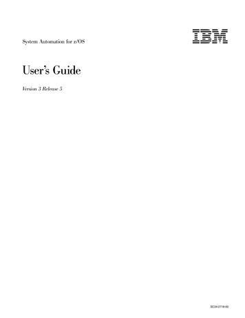
PanelView 600Operating Instructions13Setting Up Press-speed CompensationTypically, you use press-speed compensation for a variable-speed presswhen PLS or DM functions occur too late as press speed increases.Press-speed compensation is the optional automatic adjustment of theangular value from the resolver. The compensation adds an offset to thevalue so that the control system responds sooner by the amount of theoffset. The offset value reaches the setpoint before the actual value.The compensation produces an offset value proportional to press speed:Offset Ax2 Bx C10,0001001where x press speedA, B, and C are constants that you enter into the Configuration Menuscreen to obtain desired results. By choice of constants (unwantedones zero), you can make the offset: a constant proportional to press speed (gets larger as press speed increases) exponentially proportional to press speed (gets larger faster)For this relationship:Let:Then Offset:Offset constantA B 0 COffset proportional to press speedA C 0 Bx/100Offset exponentially proportional to speedC 0 Ax2 /10,000 Bx/100We suggest whole-number values 0-10.To illustrate these relationships, we graphed examples ofoffset vs press speed for different constant values.A B 0C 10Offset 10A 10, B 10, C 0Offset 10x2/10,000 10x/100 x2/1000 x/10A C 0B 10Offset 10x/100 x/1060Off 40set2060Off 40set20xxx60Off 40set20xxx00100200Press Speed300100200Press Speed3000x100200Press Speed300Enter values for constants A, B, and C on Configuration Menu, page 4.
14PanelView 600PLS/DM Active ScreensOperating InstructionsUse Active screens to edit/monitor PLS and DM functions.You access this path from the Active Menu key on the main menu.
PanelView 600Operating Instructions15PLS/DM Active MenuUse this menu to access other screens to edit/monitor DM and PLSfunctions while the press is operating, and to save-as and/or store them.Press:To:DMPLSa ss eitheraccessi h screensn to edit/monitorini thatha functionn i nSAVE ASaccess the screen to save the edited part fileSTOREstore the current part file in SLC memory Recipe filesTo Save, Store, or Save AsWe differentiate among three similar terms for saving dataassociated with editing a part file:This key:When pressed, does the following:[SAVE]Temporarily saves edited data on an Active screen untilyou store the edited part file from the Active Menu, above.Important: When you press [SAVE] from an Active screen,the outputs are immediately energized for machine response.[STORE]Returns the current Active part file to SLC recipe storage.Important: After editing an Active screen, if you omitreturning to the Active Menu and storing, the edits are lost.[SAVE AS]Copies the part file into SLC recipe storage, under thenew part file number and die ID number.Important: The copied-from part file is retained.
16PanelView 600Operating InstructionsEdit/Monitor DMUse this screen to edit/monitor die monitor functions, on line.Important: For instructions on determining DM requirements, referto User Manual (publication 6556-6.5.11), chapter 6.Channel # and Name:To select channel number 1–16, place the cursor on the datafield andrepeatedly press the up or down arrow key.To select the channel name, repeatedly press the [SELECT NAME] keythrough the list of prepared names.Mode:To select channel mode, repeatedly press the [SELECT MODE] key.Mode:staticcyclictransferin positionintermittentSignal must be seen as follows, or function sets an output action:continuouslythru a preset angular window once every cycle.thru consecutive DM inputs, following the part thru a progressive diethru a preset angular window (with part in place)thru a preset angular window after a preset number of press cycles.Intermittent mode reverts to cyclic mode after the number of cycle countsthat you preset in the INTERMITTENT CYCLE COUNT data field.Input:To select the type of input switch, toggle the [SELECT INPUT] keybetween NORMALLY CLOSED and NORMALLY OPEN.Output:Select from these actions to be taken when the system detects a DM fault.Output:warningtop stopstop nowbypassedDescription:system displays warning message but does not stop the presssystem displays warning message and top-stops the presssystem displays warning message and immediately stops the presssystem ignores the output
PanelView 600Operating Instructions17Angle ON/OFF:To preset the ON (open) and OFF (close) angles of the angular window,place the cursor on the datafield and enter the value from the keypad.When editing DM presets, remember that: For CYC and POS modes, the windowOn – – – – Window – – – – OffOn – Switch – Offdefines the zone of rotation within which orCrankshaftoutside of which the input must be detected.rotationEnter ANGLE ON/OFF angles in whole numbers.Read displayed ANGLE ON/OFF values to help set up windows.They tell you when the channel’s input switch turned On and Off. For XFR mode– entry station input is assigned to a channel with bypassed output– all sensor stations and channels in the sequence must be consecutive– all but first (entry) channel must set a stop command (detected fault)Important: After editing each channel, press [SAVE] to temporarilysave your edits. When you do, the machine may respond immediately.You must press [SAVE] before selecting the next channel, or your editsare lost.Important: After completing (and testing) all edits to an Active screen,return to the Active Menu to store or save-as. If you omit storing, youredits will be lost when you retrieve the part file for future use.Edit/Monitor PLSUse this screen to edit/monitor programmable limit switch functions, online.Important: For instructions on determining PLS requirements, referto User Manual (publication 6556-6.5.11), chapter 6.
18PanelView 600Operating InstructionsPLS Selection:To select PLS function 1–8, place the cursor on the datafield andrepeatedly press the up or down arrow key.PLS Presets:You can edit up to eight PLS functions, each with: angular turn-ON preset choice of turn-OFF preset:– angular, in units of degrees– time, in units of secondsTo enter presets, place cursor on datafield; enter value from keypad.Mode:To select the PLS mode, press the designated function key [F1] – [F4]repeatedly through the choices of OFF, TIMER, or ANGLE.Output:This area indicates whether the PLS is OFF or ON.To edit PLS outputs: Always turn On a PLS output with an angular position Turn Off a PLS output with an angular position or a preset time When using PLS with track mode, give both channels the same numberUse this procedure:1. Move cursor with arrow keys to PLS SELECTION.2. Select group of four PLS channels with ƞƟ arrow keys.3. Move cursor to PLS channel with arrow keys.4. Edit/enter PLS ON angle and OFF time or angle with keypadinto the displayed dialog box. Press return arrow to insert.5. Correct entry errors in dialog box with backspace-delete arrow.6. Complete PLS channels in groups of four.7. ATTENTION: At completion of each set of four PLS channels,press [SAVE] to temporarily save setpoints. When you do, themachine may respond immediately.8. If needed, go to the next set of four PLS channels.9. You must press [SAVE] before you can exit the screen.10.Return to the Active Menu screen to store or save-as.Important: After completing (and testing) all edits to an Active screen,return to the Active Menu to store or save-as. If you omit storing, youredits will be lost when you retrieve the part file for future use.
PanelView 600Operating Instructions19Save Part File AsUse this screen to save the edited PLS or DM function, on line.When you have completed the on–line editing of a DM or PLS function,you can save it on-line as a new part file.SAVEThe windows display the part file number you have just edited.AS PART FILETo select a new part file to save-to, repeatedly press the up/down arrowkey through the list of part file numbers, 1–20.DIE ID NUMBERThe windows display the part file number you have just edited.With cursor and keypad, enter your die ID number (10 digits, max).Important: If the Die ID window of the selected part file alreadycontains a Die ID number, the part file number you selected already hasan active file. Either select another part file number without an activefile or purposely allow your edits to overwrite the existing file.To save your edits to the designated file, press the SAVE AS hard key [F5].
20PanelView 600PLS/DM Recipe ScreensOperating InstructionsUse Recipe screens to create PLS and DM functions, off-line.You access this path from the Recipe Menu key on the main menu.
PanelView 600Operating Instructions21PLS/DM Recipe MenuUse this menu to access other screens to create DM and PLS functionsindependent of press operation, and to store, save as, and/or load them.Press:To:DMPLSa ss eitheraccessi h screensn to createa thatha parta fileiSAVE ASaccess the screen to save the part file under another name/numberLOAD JOBupload a stored part file to the SLC processor for executionSTOREstore the part file in SLC memory Recipe filesTo Save, Store, or Save AsWe differentiate among three similar terms for saving data associatedwith creating a new part file:This key:When pressed, does the following:[SAVE]Temporarily saves the data of one DM channel, a group of four PLSchannels, or entire screen until you store the part file from the Recipe Menu.Returns the current part file to storage in the file management area.Important: If you omit storing a part file from the Recipe Menu, the part fileis erased when you store some other part file, later.[STORE][SAVE AS]Copies the part file, under a new part file number and die ID number,into SLC memory Recipe files.Important: The copied-from part file is retained.To Download a Part File with [LOAD JOB] KeyTo set up and run a new part, download the new part file as follows:1. Select the part file number with arrow keys.2. Press [LOAD JOB]. This will overwrite the existing active job.3. Verify the new part file #/name on an Edit/Monitor (Active) screen.If the part file is undefined (no setpoints), active memory is cleared.
22PanelView 600Operating InstructionsDM RecipeUse this screen to create die monitor functions, off line.Important: For instructions on determining DM requirements, referto User Manual (publication 6556-6.5.11), chapter 6.Channel Number and NameSelect channel number with cursor and arrow keys. Scroll the list ofpre–determined channel names by repeatedly pressing [SELECT NAME].ModeSelect the mode by repeatedly pressing the [SELECT MODE] key:Select Mode:staticcyclictransferin positionintermittentDescription (If mode malfunctions, system triggers an output):seen continuouslyseen thru preset angular window once every cycleseen thru consecutive DM inputs, following the part thru a progressive diepart in place, seen thru preset angular windowwaits a preset number of press cycles, then reverts to cyclic modeIf setting up transfer-mode channels, channel numbers must be sequential.The first channel must be the “upstream” channel with bypassed output.Remaining channels must have a stop-action output response.OutputSelect from these responses if mode detects a DM malfunction:Select Output:warningtop stopstop nowbypassedDescription (If mode malfunctions, system triggers an output):system displays warning message but does not stop the presssystem displays warning message and top-stops the presssystem displays warning message and immediately stops the presssystem ignores the outputInputToggle [SELECT INPUT] key between normally closed and normally open.
PanelView 600Operating Instructions23Intermittent CountIf using intermittent mode, enter the number of cycle counts during whichthe mode does nothing until it reverts to cyclic mode.Angle ON/OFFEnter the turn-ON and turn-OFF angles for the DM window.For CYC and POS modes, the window defines thezone of rotation within which or outside of whichthe input must be detected. Enter angles in wholenumbers, 0–359o.On WindowOffCrankshaftrotationImportant: At completion of each channel, press [SAVE] to temporarilysave setpoints. After completing all needed channels, you must return tothe Recipe Menu to store the completed part file. If you omit storing itfrom the Recipe Menu, the part file is erased when you store some otherpart file, later.PLS RecipeUse this screen to create programmable limit switch functions, off line.Important: For instructions on determining PLS requirements, referto User Manual (publication 6556-6.5.11), chapter 6.You can create up to eight PLS channels, each with an angular turn-onpreset, and a choice of turn-off preset: either angular or timed mode.PLS SelectionSelect the PLS number with cursor and arrow keys.
24PanelView 600Operating InstructionsSet Up PLS Outputs Always turn On a PLS output with an angular position. Turn Off a PLS output with an angular position or a preset time (ms). When using PLS with track mode, give both channels the same number.Important: After completing each set of four PLS channels, press[SAVE] to temporarily save setpoints. When you have completed allneeded PLS channels, you must return the Recipe Menu to store, copy, ordownload the completed part file. If you omit storing it from the RecipeMenu, the part file is erased when you store some other part file, later.Save Recipe Part File AsUse this screen to save a new or edited part file, off line, under a newpart file number and die ID number, or to locate the file associatedwith a particular Die ID.Important: PanelView 600 stores part files with these identifiers: part file number 1–20 die ID number having up to 10 digitsSAVEThe part file and die ID numbers identify the current part file.ASFor the new part file: select a part number, then enter a die ID number.Press the [SAVE AS] key. The original part file is retained.Important: If you need to locate a Die ID number, scroll through the listof 20 part file numbers by repeatedly pressing the up/down arrow key andobserving the corresponding Die ID numbers displayed in that window.
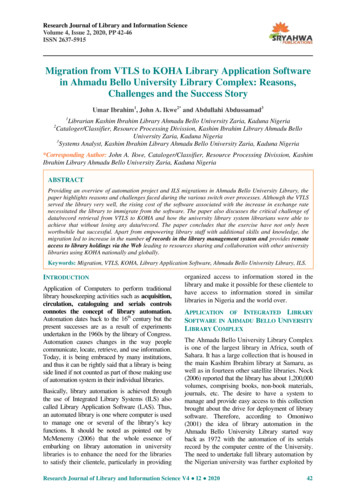
PanelView 600Monitor ScreensOperating Instructions25Use monitor screens to observe the following system operations: Machine Status to observe press speed, current position, counter balance air presure, shut height, and cycle countAlarm History to read up to 100 alarm messages in reverse orderC/B Overview to observe on/off status of rotary camsProduction Status to compare parts produced with total requiredC/B Response to observe wear of the clutch mechanismFaults & Prompts to troubleshoot detected faults, operator errorsTonnage Monitor to observe the deviation from expected tonnageYou access these screens from the main menu.ALARM HISTORYALARM MESSAGES IN REVERSE ORDER,UP TO 10 MESAGES PER SCREENUP TO 100 MESSAGS, TOTAL
26PanelView 600Operating InstructionsMachine StatusThis screen reports: shaft rotational position (press angle): from resolver vs. compensated computed strokes per minute (SPM) used for speed compensation counterbalance air pressure (PSI): setpoint vs. actual closed-loop press speed (SPM): setpoint vs. actual shut-height position (inches) cycle countUse it to observe how your machine is operating.Alarm HistoryThis screen reports the most current alarm messages: up to 10 alarm messages per screen (in reverse order) up to 100 alarm messages, total
PanelView 600Operating Instructions27C/B OverviewThis screen reports: on/off status of cam limit switches as seen by processors A and B shaft rotational position (current angle)Use it to verify proper operation and sequencing of your cam switches.From this screen, you can go to any one of the following:Touch this function key:MONITORBRAKE MONITORFAULTS/PROMPTSMAIN MENUTo do this:View progress of the production runSet up your brake monitorView fault and prompt messagesAccess other screens
28PanelView 600Operating InstructionsProduction StatusThis screen report
tonnage monitor (chnls 1, 2) TON 1-2 tonnage module in slot 7, chassis A sheets 12 tonnage monitor (chnls 3, 4) TON 3-4 tonnage module in slot 8, chassis A sheet 13 counterbalance CB analog I/O module in slot 6, chassis B sheets 9, 11 shut height SH same as counterbalance variable-speed drive SPEED same as counterbalance