Transcription
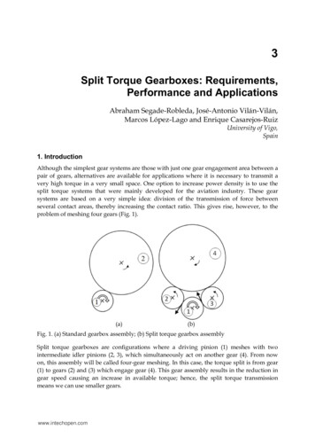
3Split Torque Gearboxes: Requirements,Performance and ApplicationsAbraham Segade-Robleda, José-Antonio Vilán-Vilán,Marcos López-Lago and Enrique Casarejos-RuizUniversity of Vigo,Spain1. IntroductionAlthough the simplest gear systems are those with just one gear engagement area between apair of gears, alternatives are available for applications where it is necessary to transmit avery high torque in a very small space. One option to increase power density is to use thesplit torque systems that were mainly developed for the aviation industry. These gearsystems are based on a very simple idea: division of the transmission of force betweenseveral contact areas, thereby increasing the contact ratio. This gives rise, however, to theproblem of meshing four gears (Fig. 1).(a)(b)Fig. 1. (a) Standard gearbox assembly; (b) Split torque gearbox assemblySplit torque gearboxes are configurations where a driving pinion (1) meshes with twointermediate idler pinions (2, 3), which simultaneously act on another gear (4). From nowon, this assembly will be called four-gear meshing. In this case, the torque split is from gear(1) to gears (2) and (3) which engage gear (4). This gear assembly results in the reduction ingear speed causing an increase in available torque; hence, the split torque transmissionmeans we can use smaller gears.www.intechopen.com
56Mechanical EngineeringThe greater the number of gears that engage the same crown, the lower the torque exercisedby each pinion. Gear assembles can have up to 14 gears engaging a single crown, ashappens, for example, in tunnel boring machines.This chapter explores four-gear meshing in a gear assembly that ensures a 50%torque splitfor each meshing area. Split torque gears are studied from two perspectives: first, the mostcommon applications of split torque gearboxes in the aeronautical sector and second, thetwo most restrictive aspects of their application, namely: The geometric limitation of the four-gear assembly that requires simultaneousengagement for all four gears. Note that the four gears do not mesh correctly in just anyposition, although they may seem to do so initially. We will describe the conditions forsimultaneous meshing of the four gears in general terms below.Torque split between the two gearbox paths must be as balanced as possible to ensurethat neither of the paths is overloaded. The technology available to ensure propertorque split between two paths will be discussed below.2. ApplicationsGear transmission requirements for aircraft are very demanding, with a standard gear ratiobetween engine and rotor of 60:1 (Krantz, 1996). Moreover, the gear transmission systemshould be safe, reliable, lightweight and vibration-free. One of the most limiting factors isweight and there are three fundamental transmission parameters that greatly affect thisfactor:1.2.3.The number of transmission stages. The greater the number of stages used to achievethe final gear ratio, the heavier the transmission, given that more common elementssuch as shafts and bearings are necessary.The number of transmission paths, the basis for split torque gearboxes. Torque isdivided between several transmission paths, resulting in a contact force in the smallergear that means that smaller, and consequently lighter, gears can be used.The final stage transmission ratio. Using a greater transmission ratio in the final stageenables weight to be reduced. This is because torque in previous steps is lower, makingit possible to use smaller gears.In helicopters, planetary gear systems are typically used for the final transmission stage,with planets consisting of between 3 and 18 gears and with planetary gearing transmissionratios between 5:1 and 7:1 (Krantz, 1996; White, 1989).Using split-path arrangements with fixed shafts in the final transmission stage is a relativelyrecent development that offers a number of advantages over conventional systems, beingseveral of them based on weight reduction for the overall transmission: It allows torque to be transmitted through various paths. This is a major advantagebecause when torque is split, the contact force between teeth is less and, hence, smaller,lighter gears can be used, therefore reducing the overall weight. Split torque howeverhas the disadvantage that the torque must be shared equally between the paths. Theproblems associated with split torque are discussed in Section 4.www.intechopen.com
Split Torque Gearboxes: Requirements, Performance and Applications 57It allows transmission path redundancy. Thus, if one transmission path fails duringflight, operation can always be assured through another path. In many cases,consequently, gear transmissions are sized so that a single path can handle 100% ofengine power.It achieves final-stage transmission ratios of around 10:1 to 14:1 (Krantz, 1996; White,1989). This improvement over the 5:1 to 7:1 ratios for planetary gearboxes (Krantz, 1996;White, 1989) is reflected in a corresponding reduction in the weight of the transmissionsystem.Several patents for transmission systems that apply split torque have been filed by SikorkyAircraft Corporation and McDonnell Douglas Helicopters (Gmirya & Kish, 2003; Gmirya,2005; Craig et al., 1998) that refer either to complete or improved power transmissionsystems from the rotorcraft or aircraft engine to the rotor or propeller. Other studies thatdescribe various aspects of split torque transmission systems, particularly their use inhelicopter gearboxes (White, 1974, 1983, 1989, 1993, 1998), conclude that such gears have anumber of advantages over traditional gear systems.Below we describe two helicopter transmission systems that use multiple path gearboxes.The first is a helicopter gearbox used for laboratory tests of torque divided into two stages,and the second is a commercial helicopter three-stage gearbox that combines bevel, spur andhelical gears.2.1 Helicopter gearbox for laboratory testingThe gear transmission described below was used to perform numerous tests on theoperation of split-torque transmissions (Krantz et al., 1992; Krantz, 1994, 1996; Krantz &Delgado, 1996), which can be considered a standard for aeronautical applications. The fullassembly is depicted in Fig. 2.Fig. 2. Helicopter transmission for laboratory testingwww.intechopen.com
58Mechanical EngineeringThe transmission is sized for input of 373 kW at a speed of 8780 rpm. As can be observed inFig. 2, the transmission has two stages: First reduction stage. The first stage is a helical gear with a input pinion with 32 teethand two output gears with 124 teeth each. The gear ratio is 3.875:1, resulting in anoutput speed of 2256.806 rpm. This is the stage where torque is split between the inputpinion and the two output gears.High torque reduction stage. The output shaft is driven by a gear which is drivensimultaneously by two spur pinions, each coaxial to the gear in the first reduction stage.The ratio between the gear teeth is 27/176, so the transmission ratio is 6.518:1, resultingin an output shaft speed of 347.6 rpm.This configuration results in torque of 9017.56 Nm. being transmitted through two paths.2.2 Commercial helicopter transmissionThis gear transmission, studied in depth by White (1998), is sized for two engines, each witha continuous rating of 1200 kW turbine at a nominal speed of 22976 rpm. The main rotorspeed is 350 rpm for an overall speed reduction ratio of nearly 66:1. Fig. 3 depicts a planview of the gear transmission and Fig. 4 is a three-dimensional view showing the gears.Fig. 3. Arrangement of gear trains between engines.Fig. 4. Three-dimensional view of the gear train arrangementwww.intechopen.com
Split Torque Gearboxes: Requirements, Performance and Applications59Total transmission reduction is achieved by three gearing stages, clearly depicted in Fig. 3and Fig. 4: Engine input. Engine torque is accepted by an overrun clutch, mounted with a bevelpinion. This bevel gear, with a between-teeth ratio of 34/84, produces a transmissionratio of 2.470:1. In this stage, the output velocity is 9299 rpm.Intermediate stage. Dual offset spur gears are driven by a single pinion. The betweenteeth ratio of 41/108 produces a transmission ratio of 2.634:1, resulting in an outputshaft speed of 3530 rpm. This meshing results in the first split in torque between thetwo intermediate gears.High-torque output stage. A double-helical gear is driven by a pinion coaxial with eachintermediate stage gear. In this stage, the torque is split again between the two helicalpinions, with the result that the output shaft simultaneously receives torque from fourpinions for each bevel gear. In this transmission it is very convenient to combine torquesplit with reduction, as greater torque is transmitted in each stage.The between-teeth gear ratio is 23/232, so the transmission ratio is 10.087:1, resulting in anoutput shaft speed of 350 rpm.This configuration uses double-helical gearing at the output stage to drive the output shaft.The helical pinions have opposing angles, which ensures equilibrium between the axial forces.When a double gear operates on the output shaft, the area of support is twice that of a simplegear. This causes a reduction in contact force, which in turn results in a reduction ratio that istwice that of the simple case, with the corresponding reduction in weight and mechanical load.Overall, this constitutes a transmission ratio of 65.64:1, with the total torque in the outputshaft exercised by each engine of 28818Nm, split between the four pinions that engage theoutput shaft crown. This calculation is based on estimating overall losses, with each inputengine operating independently, of 12%.One of the main problems in split torque transmission is ensuring equal torque splitbetween the paths. To ensure correct torque split, a long, torsionally flexible shaft is usedbetween the intermediate-stage spur gear and the output-stage helical pinions. Section 4describes the methods most frequently used to ensure correct torque split between paths.3. Feasible geometric configurationsTo ensure simultaneous meshing of four gears (Fig. 1), configuration must comply withcertain geometric constraints. A number of studies describe the complexity of simultaneousgearing in split torque gearboxes (Kish, 1993a) and in planetary gear systems (Henriot, 1979,Parker & Lin, 2004); other studies approach the problem generically (Vilán-Vilán et al.,2010), describing possible solutions that ensure the simultaneous meshing of four gears.For four gears to mesh perfectly, the teeth need to mesh simultaneously at the contactpoints. The curvilinear quadrilateral and the pitch difference are defined below in order toexpress the meshing condition. From now on we will use this nomenclature of our owndevising -that is, curvilinear quadrilateral - to indicate the zone defined by portions of pitchcircles in the meshing area (Fig. 5). The pitch difference is the sum of pitches in the inputand output gears minus the sum of pitches in the idler gears at the curvilinear quadrilateral.For perfect engagement between the four gears, the pitch difference must coincide with awhole number of pitches.www.intechopen.com
60Mechanical EngineeringFig. 5. General conditions for simultaneous meshing of four gearsA relationship is thus established between the position of the gears, as defined by therelative distance between centres, and the number of teeth in each of the gears. Below weexplore two possible cases of over-constrained gears: CASE 1. Four outside gears.CASE 2. Three outside gears and one ring gear.3.1 Case 1. Four outside gearsFor a gearbox with the geometry illustrated in Fig. 6, it is possible to locate the differentpositions that will produce suitable meshing between gears, in function of the number ofteeth in each gear, by defining the value of the angles , , and .Fig. 6. Nomenclature for the four-gear caseThe condition described in the previous section can be mathematically expressed as follows(see Nomenclature):r1 r2 r3 r4 n m www.intechopen.comn Z(1)
Split Torque Gearboxes: Requirements, Performance and Applications61where n is the pitch difference in the curvilinear quadrilateral. As previously mentioned, nmust be a whole number to ensure suitable meshing between gears.We thus obtain an equation with four unknowns ( , , , ). The three remainingrelationships can be obtained from the quadrilateral that joins the centres of the pitch circles(this quadrilateral will be denoted the rectilinear quadrilateral). Finally, we come to atranscendental equation (2) from which can be obtained according to the number of teethin the gears. c a b cos e1 f cos A1 B1 arccos 1 1 1 C 1 g1 d1 c a b .cos h1 cos A '1 B '1 arccos 1 1 1 C '1 d1 Once the angle(2)has been determined, we can calculate: c1 a1 b1 cos d1 arccos A1 B1 C 1 A '1 B '1 C '1(3)(4)(5)a1, b1, c1, d1, e1, f1, g1, h1, A1, B1, C1, A1’, B1’ and C1’ are numerical relationships among theteeth number from each wheel that must mesh simultaneously. The value of each coefficientis listed in the Appendix.The transcendental equation for obtaining has several solutions, all representing possibleassemblies for the starting gears. For example, for four-gear meshing with the next teethnumbers: z1 30, z2 50, z3 20 and z4 12 (see Nomenclature), all the possible solutions for thegear can be encountered. In this case solutions are n -12, -11, -3, -2, -1, 0, 1, 2, 3, 4, 7, 29 and 30,where n is the pitch difference between the two sides of the curvilinear quadrilateral (a wholenumber that ensures suitable meshing). Fig. 7 shows some of the possible meshing solutions.www.intechopen.com
62Mechanical EngineeringFig. 7. Feasible solutions for given numbers of teeth3.2 Case 2. Three outside gears and one ring gearIn this case torque is transmitted from a driving pinion (1) to a ring gear (2) through twoidler pinions (3) and (4). Two solutions are available depending on the geometry of therectilinear quadrilateral that joins the centres of the pitch circles, either crossed (Fig. 8 (a)) ornon-crossed (Fig. 8 (b)). The starting equation is different for each of these cases.(a)(b)Fig. 8. Solutions for three outside gears and one ring gear: (a) crossed quadrilateral (b) noncrossed quadrilateralwww.intechopen.com
63Split Torque Gearboxes: Requirements, Performance and ApplicationsFor the crossed quadrilateral configuration, the starting equation is (see Nomenclature):z1 z2 z3 z4 2 n z3 z4 (6)Finally, we come to the same transcendental equation (2), where the coefficients are a2, b2, c2,d2, e2, f2, g2, h2, A2, B2, C2, A2’, B2’ and C2’, whose values are listed in the Appendix.For the non-crossed quadrilateral configuration, the starting equation is:z1 z2 z3 z4 2 n 2 z2 z3 z4 (7)Finally, we come to the same transcendental equation (2), where the coefficients become a2,b2, c2, d2, e2, f2, g2, h2, A3, B3, C3, A3’, B3’ and C3’, whose values are listed in the Appendix.3.3 A particular case: Outside meshing with equal intermediate pinionsA common split torque gear assembly is one with two equally sized idler pinions (Fig. 9).Fig. 9. Idler pinions in an outside gearThe solution is obtained by particularizing the general solution for four outside wheels andimposing the condition z3 z4, or . The following equations are defined for thecurvilinear quadrilateral:z1 z2 2 z3 n 2 2 2 z2 z3 sin 2 2 z1 z3 sin Resolving the system, the following transcendental function in is obtained:www.intechopen.com(8)(9)(10)
64Mechanical Engineering z nz1 z3z z sin sin 3 1 3z2 z3zzz 2 32 z3 2 2 (11)The solutions for the other angles can now be obtained: z1 z3 2 arcsin z2 z3 2 sin 2 2(12)(13)4. Load sharingThe main problem in the design of split torque gearboxes is to ensure that torque is equallysplit between different paths. Small deviations in machining can result in one of the paths with100% of torque and the other path operating entirely freely (Kish & Webb, 1992). This situationcauses excessive wear in one of the paths and renders the torque split system ineffective.Below we describe approaches to ensuring equal torque split between different paths in splittorque gear arrangements. The main types are:1.2.3.Geared differential. This differential mechanism, frequently used in the automotivesector, delivers equal torques to the drive gears of a vehicle.Pivoted systems. These use a semi-floating pinion constrained both to pivot normal tothe line of action and to seek a position where tooth loads are equal.Quill shafts. A torsion divider with a separate gear and pinion, each supported on itsown bearings, are connected through the quill shaft, which allows torsional flexibility.The use of any of these systems to ensure correct torque split makes the gearbox heavier andassembly and maintenance more complex, which is why a number of authors do notsupport the use of systems that ensure torque split. Described below are the main systemsthat ensure correct torque split and discussed also are the proposals of authors whoadvocate for not using special systems.4.1 Geared differentialOne way to ensure correct torque split between two branches is to use a differential system.The great disadvantage of this system, however, is that resistive torque lost in one branchleads to loss of the full engine torque. Different differential mechanisms can be used, withassemblies very similar to those in vehicles or to the system depicted in Fig. 10. Assembled atthe entry point to the gearbox is an input planetary system that acts as a differential thatensures load sharing. This transmission accepts power from three input engines, each of whichhas a differential system that ensures balanced torque splitting. Power is input from eachengine to the sun gear of the differential planetary system. The carrier is the output to a bevelpinion that drives one torque splitting branch while the ring gear drives the other torquesplitting branch. As the carrier and the ring gear rotate in opposite directions, the bevel pinionsare arranged on opposite sides to ensure correct rotation direction. Each output bevel geardrives one pinion which then combines power into the output gear.www.intechopen.com
Split Torque Gearboxes: Requirements, Performance and Applications65Fig. 10. Schematic view of split torque main transmission4.2 Pivoted systemsOne type of pivoted systems is described in detail in a patent (Gmirya, 2005) for split torquereduction applied to an aerial vehicle propulsion system (Fig. 11). “The input pinion (64)engages with gears (66) and (68). The input pinion is defined along the gear shaft AG, the first gearFig. 11. Perspective view of the split torque gearbox with pivoted engine support (Gmirya, 2005)www.intechopen.com
66Mechanical Engineering(66) defines a first gear rotation shaft A1 and the second gear (68) defines a second gearrotation shaft A2. The axes AG, A1 and A2 are preferably located transversally to the pivotaxis Ap. The first gear (66) and the second gear (68) engage an output gear (70). The outputgear (70) defines an output rotation shaft A0 and is rotationally connected to thetranslational driveshaft (44) and the rotor driveshaft (46) to power, respectively, thetranslational propulsion system and the rotor system”.The assembly transmits torque from the pinion (64), which operates at very high revolutions,to the output shaft (44 -46) via two paths. The pivot system works as follows: since the inputpinion (64) meshes with two gears (66) and (68), the pivoted engine arrangement permits theinput pinion (64) to float until gear loads between the input gear (64), the first gear (66) and thesecond gear (68) are balanced. Irrespective of gear teeth errors or gearbox shaft misalignments,the input pinion will float and split torque between the two gears.4.3 Quill shaftsBelow we describe assemblies used in systems that allow some torsion in the split torqueshafts (Smirnov, 1990; Cocking, 1986) in order to minimize the difference in torque splitbetween paths. These systems achieve their goal in several ways: Conventional systems (Kish, 1993a) assemble intermediate shafts with some torsionalflexibility so that angular deviation produced between the input and output pinionsadjusts the torque transmitted via the two paths.Other systems are based on elastomeric elements in the shaft (Isabelle et al., 1992, Kish& Webb, 1992) or materials with a lower elastic modulus (Southcott, 1999), such as anidler pinion constructed of nylon or a similar material (Southcott, 1999). This solution isnot explored here because the torque transmitted is reduced.Yet other systems operate on the basis of spring elements (Gmirya & Vinayak, 2004).The use of such elements in the design adds weight and makes both initial assembly andmaintenance more complex, thereby losing to some degree the advantages of split torquegearboxes. Described below are the most representative types of quill shaft.4.3.1 Conventional quill shaftsConventional quill shaft design involves assembly on three different shafts (Fig. 12). TheFig. 12. Conventional assembly of a quill shaftwww.intechopen.com
Split Torque Gearboxes: Requirements, Performance and Applications67input shaft (1) is assembled with two separate bearings (2) and the input gear (3).The outputshaft (4) is assembled with two separate bearings (5) and, in this case, two output pinions(6). The quill shaft is a third shaft (7) that connects the other two shafts. Due to a lower polarmoment of inertia, it admits torsional flexibility, resulting in a small angular deviationbetween the input and output shafts. The value of the angular deviation is proportional tothe transmitted torque; thus, if one path transmits more torque than the other, the angulardeviation is greater, allowing the shaft that transmits less torque to increase its load.4.3.2 Quill shafts based on elastomeric elementsElastomeric elements are frequently used in quill shafts given their low elastic modulus. Forexample, one system (Isabelle et al., 1992), based on using elastomers (Fig. 13), consists of“an annular cylindrical elastomeric bearing (14) and several rectangular elastomeric bearing pads(16). The elastomeric bearing (14) and bearing pads (16) have one or more layers (60); each layer (60)has an elastomer (62) with a metal backing strip (64) secured by conventional means such asvulcanization, bonding or lamination”.Fig. 13. Elastomeric load sharing device (Isabelle et al., 1991)The annular cylindrical elastomeric bearing (14) absorbs possible misalignments betweenshafts resulting from defects in assembly. The rectangular elastomeric bearing pads (16) areresponsible for providing torsional flexibility to the shafts of the possible gear paths in orderto ensure equal torque transmission.Another elastomer-based system (Kish & Webb, 1992) (Fig. 14) consists of an assembly with“a central shaft (21) and a pair of bull pinions (22) and (23). The shaft (21) is supported by thebearings (24) and (25); a gear flange (26) at the end of the shaft has bolt holes (27) and teeth (28) onthe outer circumference. A spur gear (29) is held to the flange (26) using upper and lower rims (30)and (31), consisting of flat circular disks (32) with bolt holes (33) and an angled outer wall (34).Gussets (35) between the wall and the disk increase rim stiffness to minimize deflection. One or moreelastomer layers (36), bonded to the outer surface (37) of the wall (34), act as an elastomeric torsionalisolator”.www.intechopen.com
68Mechanical EngineeringFig. 14. Gear assembly using an elastomeric torsional isolator (Kish & Webb, 1992)This assembly was tested in the Advanced Rotorcraft Transmission project (Kish, 1993a), bycomparing it with conventional quill shafts. It was concluded that the torque split wasexcellent and also had other advantages such as lower transmission of force to supports, lessvibration and less noise during operation.The main problem with using elastomers to achieve proper torque split is their degradationover time, especially when used in high-torque gear transmissions where temperatures arehigh and there is contact with oil. Some authors therefore propose the use of metallicelements to achieve the same effect as the quill shaft.4.3.3 Quill shafts based on spring elementsSome authors propose the use of metallic elements to achieve the same effect as the quillshaft. One such system (Gmirya & Vinayak, 2004) (Fig. 15) is based on achieving this effectby using “at least one spring element (30) placed between and structurally connecting the gear shaft(32) and the outer ring of gear teeth (34). The gear shaft (32) has flange elements (36) that projectradially outboard of the shaft. The ring of gear teeth (34), similarly, has a flange element (38) thatprojects radially inward towards the gear shaft”. In this case, a pair of spring elements (30) isarranged on each side of the gear teeth flange element (38)”.This assembly is designed in such a way that the spring elements absorb torsional deflectionbetween the gears, thereby ensuring proportional torque split between paths.4.4 No use of special systemsSplit torque gearboxes are used in order to reduce the weight of the gear system, so thesimplest option is assembly without special systems for regulating torque split. Severalauthors support this option, for example, Kish (1993a, 1993b), who concluded from tests thatacceptable values can be achieved without using any special torque split system, simply bywww.intechopen.com
Split Torque Gearboxes: Requirements, Performance and Applications69Fig. 15. Load sharing gear in combination with a double helical pinion (Gmirya & Vinayak,2004)ensuring manufacturing according to strict tolerances and correct assembly. Krantz (1996)proposed the use of the clocking angle as a design parameter to achieve adequate torquesplit between paths. This author has studied the effects of gearshaft twisting and bending,and also tooth bending, Hertzian deformations within bearings and the impact of bearingsupport movement on load sharing.Krantz (1996) defined the clocking angle as and described the assembly prepared formeasurement (Fig. 16): “The output gear is fixed from rotating and a nominal counter-clockwiseFig. 16. Assembly for measurement of the clocking anglewww.intechopen.com
70Mechanical Engineeringtorque is applied to the input pinion so that the gear teeth come into contact. When all the gear teethfor both power paths come into contact, then the clocking angle β is, by definition, equal to zero. If theteeth of one power path are not in contact, then the clocking angle β is equal to the angle that the firststage gear would have to be rotated relative to the second-stage pinion to bring all the teeth intocontact”.The tests show that suitable (47 per cent/53 per cent) load sharing can be achieved merelyby taking into account the clocking angle and ensuring proper machining and assembly.This research into the clocking angle has been followed up by subsequent authors (Parker &Lin, 2004) who have studied how contact between different planetary gears is sequenced.5. ConclusionChoosing the correct assembly for aircraft power transmission is a key factor in the quest forweight reduction. Although technological advances in mechanical components can helpachieve weight reduction in gear systems, their influence is much less than that of choosingthe correct gear assembly.Planetary gear or split torque systems are typically used in helicopter gear transmissions.The fundamental advantage of the split torque systems is that less weight is achieved byequal torque transmission and gear transmission ratios. This advantage is based primarilyon arguments as follows: In the final transmission stage where the greatest torque is achieved, the use of severalpaths for the transmission ratio means that, given equal torque and stress levels in theteeth, the ratio between output torque/weight will be better in torque split gear systemsthan in planetary gear systems.In the final transmission stage, transmission ratios of around 5:1 or 7:1 are achieved byplanetary gearboxes used with a single stage, compared to 10:1 or 14:1 for split torquegears used in the final stage.The possibility of achieving higher transmission ratios in split torque gearboxes makesit possible to use a smaller number of gear stages, resulting in lighter gear systems.Split torque gearboxes need fewer gears and bearings that planetary gearboxes, whichmeans lower transmission losses.A key factor for aircraft use is that split torque gearboxes improve reliability by usingmultiple power paths; thus, if one path fails, operation is always assured throughanother path.The main disadvantage of the split torque gearboxes is when torque split between thepossible paths is uneven; however, several solutions are available to ensure correcttorque split.These arguments would indicate the advisability of using this type of transmission inaircraft gear systems.6. Nomenclaturemrigear moduleradius of the pitch circle of wheel iwww.intechopen.com
Split Torque Gearboxes: Requirements, Performance and Applicationszin71number of teeth in wheel iangle formed by the lines between centres, between wheels 3 4 1angle formed by the lines between centres, between wheels 3 2 4angle formed by the lines between centres, between wheels 2 3 1angle formed by the lines between centres, between wheels 1 4 2pitch difference between the two sides of the curvilinear quadrilateral7. AppendixThe numerical relationships among the teeth number used in the text are listed below. C1,C1', C2, C2', C
In helicopters, planetary gear systems are typically used for the final transmission stage, with planets consisting of between 3 and 18 gears and with planetary gearing transmission ratios between 5:1 and 7:1 (Krantz, 1996; White, 1989). Using split-path arrangements with fixed shafts in the final transmission stage is a relatively