Transcription
Dell PowerVault TL2000 Tape Library and TL4000 TapeLibraryUser's Guide
Dell PowerVault TL2000 Tape Library and TL4000 TapeLibraryUser's Guide
iiDell PowerVault TL2000 Tape Library and TL4000 Tape Library: User's Guide
Information in this document is subject to change without notice. 2015 Dell Inc. All rights reserved.Reproduction in any manner whatsoever without the written permission of DellInc. is strictly forbidden. Trademarks used in this text: Dell, the DELL logo andPowerVault are trademarks of Dell Inc.Other trademarks and trade names might be used in this document to refer toeither the entities claiming the marks and names or their products. Dell Inc.disclaims any proprietary interest in trademarks and trade names other than itsown.Printed October 2015iii
ivDell PowerVault TL2000 Tape Library and TL4000 Tape Library: User's Guide
Read this firstMinimum firmware levels for common library featuresTable 1. Minimum firmware levels for common library featuresFeatureMinimum Firmware Level(s) RequiredLTO HH V2 Tape DrivesLibrary firmware level must be at A.00, orgreater, to support HH V2 Tape Drives.LTO 7 Tape DriveLibrary firmware must be at D.10 or greaterto support the Ultrium 7 drives. Ensure theminimum version required to supportUltrium 7 tape drives are installed on thehost. Ensure that any host applications andsoftware using their own device drivers areat the minimum level required to supportUltrium 7 tape drives.LTO 6 Tape DriveLibrary firmware must be at B.50 or greaterto support the Ultrium 6 drives. Ensure theminimum version required to supportUltrium 6 tape drives are installed on thehost. Ensure that any host applications andsoftware using their own device drivers areat the minimum level required to supportUltrium 6 tape drives.LTO 5 Tape DriveLibrary firmware must be at 9.00, or greater,to support the Ultrium 5 drives. Ensure theminimum version required to supportUltrium 5 tape drives are installed on thehost. Ensure that any host applications andsoftware using their own device drivers areat the minimum level required to supportUltrium 5 tape drives.Library BCR (Bar Code Reader)Libraries manufactured after May 2010 mayhave a BCR that requires a minimum levelof library firmware. The minimum level offirmware for these libraries is 9.00. Attemptsto downlevel these libraries below 9.00 willbe blocked by the library.Dedicated Cleaning Slot removalLibrary firmware level must be greater than3.90.EncryptionLibrary firmware level must be 5.80 orgreater.LTO4 Drive firmware level must be 77BE orgreater.Key Path DiagnosticsLibrary firmware level must be greater than6.3, if feature is available.Path FailoverLTO 4 Tape Drives: No minimum level offirmware is required.IPv6 SupportLibrary firmware level: 4.50v
Contacting DellFor customers in the United States, call 800-WWW-DELL (800-999-3355).Note: If you do not have an active Internet connection, you can find contactinformation about your purchase invoice, packing slip, bill, or Dell product catalog.Dell provides online and telephone-based support and service options. Serviceavailability varies by country and product, and some services might not beavailable in your area. To contact Dell for sales, technical support, or customerservice issues follow the steps that are listed:1. Visit www.Dell.com/support.2. Verify your country or region in the Choose A Country/Region menu at thebottom of the page.3. Click Contact Us on the left side of the page.4. Select the appropriate service or support link that is based on your need.5. Choose the method of contacting Dell that is convenient for you.viDell PowerVault TL2000 Tape Library and TL4000 Tape Library: User's Guide
ContentsiiiRead this first . . . . . . . . . . .vMinimum firmware levels for common libraryfeatures . . . . . . . . . . . . . . .Contacting Dell . . . . . . . . . . . .vviFigures . . . . . . . . . . . . . .ixTables . . . . . . . . . . . . . .xiiiSafety and environmental notices . .xvDanger and caution notices . . . . . . . .xvLaser Safety and Compliance . . . . . . .xviPerforming the safety inspection procedure . .xviRack safety . . . . . . . . . . . . .xviiPreface . . . . . . . . . . . . .xixChapter 1. Product Description . . . .1Front Panel . . . . . . . . . . . . .Rear Panel . . . . . . . . . . . . .Bar Code Reader . . . . . . . . . . .Encryption . . . . . . . . . . . . .Supported Internet Protocols . . . . . . .SNMP Messaging . . . . . . . . . . .SNMP Traps . . . . . . . . . . .Maximum Library Storage Capacity and DataTransfer Rate . . . . . . . . . . . .Ultrium Tape Drives . . . . . . . . . .Speed Matching . . . . . . . . . .Channel Calibration . . . . . . . .Power Management . . . . . . . .Media . . . . . . . . . . . . . .Library Specifications . . . . . . . . .Product Environment . . . . . . . . .Supported Device Drivers . . . . . . .1355777.8910101111121415Chapter 2. User Interfaces . . . . .Operator Control Panel . . . . . .Operator Control Panel Philosophy .Power-ON Display . . . . . . .Note about the Front Panel LEDs . .Input Modes . . . . . . . . .Power ON/OFF . . . . . . . .Web User Interface . . . . . . . .Login . . . . . . . . . . .System Status. . . . . . . . .Web User Interface Help Pages . . .Logging out of the Web User Interface.Chapter 3. Installation Planning . . .Determining the Number of Logical Libraries .1717171818192020212224242525Basic Guidelines . . . . . . . . . . .Library Sharing . . . . . . . . . . .Using Multiple Logical Libraries for LibrarySharing . . . . . . . . . . . . . .Using Multiple Control Paths . . . . . . .Using Multiple Control Paths for Path FailoverLibrary Partitioning and Element Addressing . .Logical Unit Number (LUN) Scanning . . . .Host Interfaces . . . . . . . . . . . .SCSI Interface . . . . . . . . . . .SAS Interface . . . . . . . . . . . .Fibre Channel Interface . . . . . . . .Chapter 4. Installation andConfiguration . . . . . . . . . . .Using the Library Configuration Form . . . .Installing Your Library. . . . . . . . . .Choosing a Location . . . . . . . . .Unpacking the Library. . . . . . . . .Verifying the shipment . . . . . . . .Installing the Library Foot Pads (for DesktopInstallation ONLY) . . . . . . . . . .Removing and Storing the Shipping Lock . .Rackmounting the Library (for Rack InstallationONLY) . . . . . . . . . . . . . .Connecting the Host Interface Cable . . . .Connecting a Power Cord . . . . . . .Configuring Your Library. . . . . . . . .Choosing Your Configuration Method . . .Using Factory Defaults as Your Configuration .Configuring Your Library using the Web UserInterface . . . . . . . . . . . . .Configuring Your Library using the OperatorControl Panel. . . . . . . . . . . .Preparing the Host . . . . . . . . . . .Verifying the Connection . . . . . . . . .Cartridge magazines . . . . . . . . . .Populating the Library with Data Cartridges .Inserting the Cleaning Cartridge . . . . 556737373747879Chapter 5. Operations . . . . . . .81Operator Control Panel Navigation . . . . .Operator Control Panel Menu Tree . . . . .Monitor Menu . . . . . . . . . . .Control Menu . . . . . . . . . . .Configure Menu . . . . . . . . . . .Service Menu . . . . . . . . . . .Web User Interface Menus . . . . . . . .Monitor Library Menu . . . . . . . .Manage Library Menu . . . . . . . .Configure Library Menu. . . . . . . .Service Library Menu . . . . . . . .Import and Export Media during Normal LibraryOperation . . . . . . . . . . . . .Configuring I/O Stations and Reserving Slots .8789909698109112113121123138146147vii
Chapter 6. Using Ultrium Media. .Data Cartridges . . . . . . . . . . .Cartridge Compatibility . . . . . . . .WORM (Write Once, Read Many) Cartridges . .WORM Media . . . . . . . . . . .Data Security on WORM Media . . . . .WORM Media Errors . . . . . . . . .Cleaning Cartridge . . . . . . . . . .Bar Code Label . . . . . . . . . . . .Guidelines for Using Bar Code Labels . . .Write-Protect Switch . . . . . . . . . .Handling the Cartridges . . . . . . . . .Provide Training . . . . . . . . . .Ensure Proper Packaging . . . . . . .Provide Proper Acclimation and EnvironmentalConditions . . . . . . . . . . . .Perform a Thorough Inspection . . . . .Handle the Cartridge Carefully . . . . .Environmental and Shipping Specifications forTape Cartridges . . . . . . . . . . .Chapter 7. Troubleshooting . . . .Installation Problems . . . . . . . . . .Library Recovery Problem Determination . . .Procedures for Isolating CRU Problems. . . .Isolating a Power Supply Problem . . . .Isolating Drive Sled Problems . . . . . .Isolating a Library Controller Card vs. AccessorEnclosure Problem . . . . . . . . .Isolating Web User Interface Problems . . .Isolating Accessor Scanner Problems. . . .Isolating Host Attachment Interface ProblemsIdentifying a Suspect Cartridge . . . . . 57158159164165165165167168169170170170Chapter 8. Error codes . . . . . .173Chapter 9. Service Procedures . . .187Removing Cartridges from Magazine Slots . .187Releasing the Magazines Manually . . . . .187Using the ITDT Firmware Update, Dump Retrievaland Drive Test Tool . . . . . . . . . .191Chapter 10. Check, Adjust, Remove,and Replace . . . . . . . . . . .Tools Required . . . . . .Electrostatic Discharge . . .Relocating Your Library . . .Removing/Installing/Adding aRemoving a Tape Drive SledInstalling a Tape Drive SledAdding a Tape Drive Sled .Replacing a Power Supply . .viii. . . . . . . . . . . . . . . .Tape Drive Sled. . . . . . . . . . . . . . . . . . . . .193193193193195196197200201Replacing a Library Controller Card . . . . .Replacing Cartridge Magazines . . . . . .Replacing the Library Enclosure . . . . . .Preparing the Defective Library for ReplacementUnpacking and Preparing the ReplacementLibrary Enclosure . . . . . . . . . .Installing your drive in the replacement libraryenclosure . . . . . . . . . . . . .Swapping Power Supplies . . . . . . .Swapping Library Controller Cards . . . .Swapping Cartridge Magazines . . . . .Installing the Replacement Library EnclosureCompleting the Installation of the ReplacementLibrary Enclosure . . . . . . . . . .Returning the Defective Library Enclosure. .202203203204205207209211213215217217SCSI Element Types, SCSI Addresses,and Physical Configurations . . . . 2192U Library I/O Slot, Storage Slots and Drive SlotElement Addresses and Physical Locations . .2194U Library I/O Slots, Storage Slots, and Drive SlotsElement Addresses and Physical Locations . .220Library Partitioning and Element Addressing. .221TapeAlert Flags . . . . . . . . .TapeAlert Flags Supported by the Library .TapeAlert Flags Supported by the Drive .227.Sense Data . . . . . . . . . . .Library sense data .Drive Sense Data .Enabling LUN Support in LinuxRed Hat Enterprise Linux . . . .Enabling LUN Support in Netware .233. .233239249.Notes on IPv6 Compatibility withWindows 2003/XP and 2008/Vista . .Notes on IPv6 Compatibility with Linux .227229250250253.254SNMP Status MIB Variables and Traps 255Library Configuration Form . . . .257Accessibility . . . . . . . . . . .259Glossary . . . . . . . . . . . .261Index . . . . . . . . . . . . . .281Dell PowerVault TL2000 Tape Library and TL4000 Tape Library: User's Guide
Figures1. Front panel of a 2U library . . . . . . .12. Front panel of a 4U library . . . . . . .23. Rear panel (drive sled only) of a half heightFibre Channel drive . . . . . . . . .34. Rear panel of a 4U library with full height FibreChannel drive and half height SAS drives . .35. Rear panel of a 2U library with a full heightdual port SAS drive . . . . . . . . .46. Library drive sled without ESD springs (SCSIsled shown) . . . . . . . . . . .107. Library drive sled with ESD springs [1] (SASsled shown) . . . . . . . . . . .108. Power-ON screens . . . . . . . . .189. Web User Interface login page . . . . .2210. 2U library System Status screen . . . . .2211. 4U library System Status screen . . . . .2212. 4U library System Status screen showingmedia attention status . . . . . . . .2313. 4U library System Status screen showing apower supply failure . . . . . . . .2314. Configuration of a one - partition system2815. Configuration of a two - partition system2816. Configuration of a three - partition system2917. Configuration of a four - partition system2918. Examples of SCSI element addressing . . .3019. Removing the plastic protective sheets fromthe library . . . . . . . . . . . .3820. Installing foot pads on the bottom of thelibrary enclosure . . . . . . . . . .4021. Shipping lock and label . . . . . . .4122. Removing the Shipping lock and label . .4123. Library shipping lock and label storagelocation on rear panel of library. . . . .4224. Rack Kit A mounting hardware . . . . .4325. Rack Kit B mounting hardware . . . . .4426. Examples of EIA units for round hole andsquare hole installations . . . . . . .4527. Rear view of Rack Kit A which shows thenarrow part of the rail located at the rear ofthe rack. . . . . . . . . . . . .4528. Rear view of Rack Kit B shows a differentmounting method . . . . . . . . .4629. Kit A (top picture with circles) showing railsinstalled. Rack Kit B is below showing thefront view of this kit installed. . . . . .4730. 2U library rack anchors and mounting brackets 4831. Close-up view of mounting of the anchors onboth sides of the library . . . . . . .4832. 2U library side screws to remove . . . .4933. Sliding the 2U library into the rack . . .5034. Sliding the 4U library into the rack . . .5035. Securing the 2U library to the rack . . . .5136. Securing the 4U library to the rack . . . .5237. Attaching a SCSI host interface cable to the 2Ulibrary . . . . . . . . . . . . .5338. Attaching host interface cables to the 4Ulibrary . . . . . . . . . . . . .39. Attaching a SAS interface cable to the 2Ulibrary . . . . . . . . . . . . .40. Removing the protective label from the powerreceptacle . . . . . . . . . . . .41. Log in screen on the Web User Interface42. The 2U library Configure Library: Generalscreen . . . . . . . . . . . . .43. Example: The 4U library Configure Library:General screen . . . . . . . . . .44. The 4U library Configure Library: LogicalLibraries page. . . . . . . . . . .45. The Configure Library: Path Failover FeatureActivation screen. . . . . . . . . .46. Feature Key verification screen . . . . .47. Feature Activation Key screen . . . . .48. Configure Library: Encryption Activationscreen . . . . . . . . . . . . .49. The Configure Library: Drive screen . . .50. Configure Library: Network Page . . . .51. Warning Screen . . . . . . . . . .52. The Configure Library: User Access screen53. The Configure Library: Date and Time screen54. The Configure Library: Logs and Traces screen55. The Configure Library: Email Notificationscreen . . . . . . . . . . . . .56. Configure Library: SNMP page . . . . .57. 2U library left magazine . . . . . . .58. 2U library right magazine . . . . . . .59. 2U library I/O station in the left magazine60. 4U library left magazines . . . . . . .61. 4U library right magazines . . . . . .62. 4U library I/O station in the lower leftmagazine . . . . . . . . . . . .63. Finger Holes on back side of 4U library I/Ostation . . . . . . . . . . . . .64. 2U Library Control Keys . . . . . . .65. 4U Library Control Keys . . . . . . .66. Operator Control Panel Menu Tree . . . .67. Monitor: Library menu. . . . . . . .68. Monitor: Drive menu . . . . . . . .69. Example of a 4U Monitor: Inventory menu70. Overview of inventoried cartridges: Leftmagazines of a 4U Library . . . . . .71. Detailed information on cartridges residing ina magazine. . . . . . . . . . . .72. Control: I/O station menu . . . . . .73. Control: Move Cartridges menu. . . . .74. Control: Magazine menu . . . . . . .75. Control: Re-Inventory menu . . . . . .76. Configure: Logical Libraries menu . . . .77. Configure: Library menu. . . . . . .78. Configure: Drive menu . . . . . . .79. Configure: Network menu . . . . . .80. Configure: Set Access PIN menu . . . 77888889091939595969697979899100103104105ix
81. Pound sign (#) shows accessible menus whenaccess PIN is enabled but before it is entered .82. Configure: Save/Restore menu. . . . .83. Configure: Set Date and Time menu . . .84. Configure: Path Failover . . . . . . .85. Service: Library Verify menu . . . . .86. Service: Run Tests menu . . . . . . .87. Service: Service menu . . . . . . . .88. Service: Display Contrast menu . . . .89. The 4U library Monitor Library: LibraryIdentity page. . . . . . . . . . .90. The 4U library Monitor Library: DriveIdentity page showing one Ultrium 3 SAShalf height V2 drive (#1) and one Ultrium 4SAS half height drive (#2) . . . . . .91. The 4U library Monitor Library: LibraryStatus page . . . . . . . . . . .92. The 4U library Monitor Library: Drive Statuspage . . . . . . . . . . . . .93. The 2U library Monitor Library: Inventorypage . . . . . . . . . . . . .94. The 4U library Monitor Library: Inventorypage (Right Magazines) . . . . . . .95. Manage Library: Move Media page . . .96. Manage Library: Perform Inventory page97. Manage Library: Release Magazine page98. The 4U library Configure Library: Generaland Extended page . . . . . . . .99. The 4U library Configure Library: LogicalLibraries page . . . . . . . . . .100. The 4U library Configure Library: PathFailover page . . . . . . . . . .101. Path Failover license verification page102. Feature Activation Key screen . . . . .103. Configure Library: Encryption Featureconfiguration screen . . . . . . . .104. The Configure Library: Drives page for a 2Ulibrary . . . . . . . . . . . . .105. The Configure Library: Drives page for a 4Ulibrary . . . . . . . . . . . . .106. Configure Library: Network Page . . . .107. Warning Screen . . . . . . . . . .108. Configure Library: User Access page109. The Configure Library: Date & Time page110. Configure Library: Logs & Traces page111. Configure Library: Event Notification page112. Configure Library: SNMP page . . . .113. Configure Library: Save/Restore page114. No Cleaning Required . . . . . . .115. No cleaning cartridge in library . . . .116. Service Library: Clean Drive page. . . .117. Service Library: View Logs page . . . .118. Service Library: View Drive Logs screen119. Service: Save Drive Dump . . . . . .120. Service Library: Perform Diagnostics page121. Service Library: Perform Key PathDiagnostics page . . . . . . . . .122. The Service Library: Upgrade Firmware page,showing one Ultrium 3 SAS Half Height V2drive and one Ultrium 4 SAS Half Heightdrive. . . . . . . . . . . . . 155.156.143157.158.145Service Library: Reboot page . . . . .The LTO Ultrium Data Cartridge . . . .Ultrium Data and WORM Tape CartridgesSample bar code label on the LTO Ultrium 7Tape Cartridge . . . . . . . . . .Setting the write-protect switch . . . .Double-boxing tape cartridges for shippingChecking for gaps in the seams of a cartridgeA 250w power supply with LEDs . . . .A 80w power supply without LEDs . . .Access holes for the left magazine . . .Access holes for the right magazine . . .Left magazine pulled out of the 2U libraryLeft Magazines pulled out of the 4U LibraryESD label . . . . . . . . . . . .Shipping Lock and Label Storage LocationShipping Lock and Label . . . . . .Library drive sled without ElectroStaticDischarge (ESD) springs (SCSI sled shown) .Library drive sled with ESD springs [1] (SASsled shown) . . . . . . . . . . .Drive sled components (full height fibre drivein top position, half height SCSI drive inmiddle position, half height SAS drive inbottom position) on back panel of a 4Ulibrary . . . . . . . . . . . . .Pulling the drive sled out of the library (drivesled without ESD springs shown) . . . .Pushing the drive sled into the library (drivesled without ESD springs shown) . . . .Diagrams for applying conductive tape forESD protection to the back of a drive sledinstalled in a 2U or 4U library . . . . .A power supply being removed from a 2Ulibrary . . . . . . . . . . . . .A Library Controller Card being removedfrom the library . . . . . . . . . .Removing the two mounting bracket screwsanchoring the library to the rack (one screwon each side of the library) . . . . . .Foot pads installed on the bottom of thelibrary enclosure . . . . . . . . .Removing the shipping label and lock fromthe top of the library and storing on the rearpanel . . . . . . . . . . . . .Library shipping lock and label storagelocation on the real panel of the library . .Removing a drive sled from the library (drivesled without ESD springs shown) . . . .Drive sled taping diagrams . . . . . .A power supply being removed from alibrary . . . . . . . . . . . . .Removing a Library Controller Card from thelibrary . . . . . . . . . . . . .Library front panel LEDs . . . . . .Access hole for the left magazine (facing rearof library) . . . . . . . . . . . .Access hole for the right magazine (facingrear of library) . . . . . . . . . .Left magazines pulled out of a 4U library(facing front of library) . . . . . . .Dell PowerVault TL2000 Tape Library and TL4000 Tape Library: User's 2213213214215
159. Mounting brackets and anchors for securingthe library in a rack (one bracket and anchoron each side of the library) . . . . . .160. Front view of rack showing screw placement161. Configuration of a one - partition system216216222162.163.164.165.Configuration of a two - partition systemConfiguration of a three - partition systemConfiguration of a four - partition systemExamples of SCSI element addressingFigures223223224224xi
xiiDell PowerVault TL2000 Tape Library and TL4000 Tape Library: User's Guide
.19.20.21.22.23.24.25.26.27.28.29.Minimum firmware levels for common libraryfeatures . . . . . . . . . . . . .2U library and 4U library front paneldescriptions . . . . . . . . . . . .2U library and 4U library rear paneldescriptions . . . . . . . . . . . .Tape drive model and host interface typeLibrary storage capacity and data transfer ratePhysical Specifications . . . . . . . .Power Specifications . . . . . . . .Operation Specifications: Ultrium 7 . . .Operation Specifications: Ultrium 6 . . .Operation Specifications: Ultrium 5 . . .Operation Specifications: Ultrium 4 . . .Operation Specifications: Ultrium 3 . . .Environmental Specifications . . . . . .Host Drive Interface Support. . . . . .Maximum bus length between terminatorsRecommended maximum quantity of drivesper SCSI bus . . . . . . . . . . .Location criteria . . . . . . . . . .Menu navigation shortcuts . . . . . .Library Control Keys . . . . . . . .Detailed information on cartridges residing ina magazine. . . . . . . . . . . .Factory Default Settings . . . . . . .Web User Interface Menus . . . . . .Library Identity page elements . . . . .Drive Identity page elements . . . . .Library Status page elements . . . . .Drive Status page elements . . . . . .Configure Library: General page elementsConfigure Library: Specific page elementsDrive Identity page elements . . . . 1611712312312947.48.49.50.51.Cartridge Types and Colors . . . . . .Cartridge Data Capacity and RecordingFormats . . . . . . . . . . . .Nominal Cartridge Life: Load/Unload CyclesUltrium data cartridge compatibility withUltrium tape drive . . . . . . . . .Bar code label requirements for Ultrium tapedrives and libraries . . . . . . . .Cartridges and VOLSERs compatible with theUltrium Tape Drives . . . . . . . .Location of the write-protect switch . . .Environment for operating, storing, andshipping the LTO Ultrium Tape Cartridge .Troubleshooting table . . . . . . . .Power Supply LED Meanings . . . . .Main Error Codes . . . . . . . . .Sub error codes . . . . . . . . . .Warning events . . . . . . . . . .Shipping Lock/Shipping Label. . . . .2U library SCSI Element Types and ElementAddresses. . . . . . . . . . . .4U library SCSI Element Types and ElementAddresses. . . . . . . . . . . .2U library SCSI element addresses for storageslots and drive slot (one logical partition withone drive). . . . . . . . . . . .4U library SCSI element addresses for storageslots and drive slot (one logical partition withdrives in slot 1 and slot 2) . . . . . .TapeAlert Flags Supported by the UltriumTape Drive . . . . . . . . . . .Library Sense Keys, ASC and ASCQ . . .LTO Tape Drive Sense Data . . . . . .SNMP Status Events . . . . . . . 20220229233239255xiii
xivDell PowerVault TL2000 Tape Library and TL4000 Tape Library: User's Guide
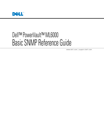
Safety and environmental noticesWhen this product is used, observe the danger, caution, and attention notices thatare contained in this guide. The notices are accompanied by symbols that representthe severity of the safety condition.The sections that follow define each type of safety notice and give examples.Danger and caution noticesDanger NoticeA danger notice calls attention to a situation that is potentially lethalor extremely hazardous to people. A lightning bolt symbol alwaysaccompanies a danger notice to represent a dangerous electricalcondition.Caution NoticeA caution notice calls attention to a situation that is potentially hazardous topeople because of some existing condition. A caution notice can be accompaniedby one of several symbols:If the symbol is.It means.A hazardous electrical condition with less severity thanelectrical danger.A hazardous condition that is not represented by othersafety symbols.A hazardous condition due to the use of a laser in theproduct. Laser symbols are always accompanied by theclassification of the laser as defined by the U. S.Department of Health and Human Services (for example,Class I, Class II).A hazardous condition due to mechanical movement in oraround the product.32-55 kg (70.5-121.2 lbs)svc00168A hazardous condition due to the weight of the unit.Weight symbols are accompanied by an approximation ofthe product's weight.xv
If the symbol is.It means.A hazardous condition due to the unit's susceptibility toelectrostatic discharge.Laser Safety and ComplianceBefore the library is used, review the following laser safety information.Class I Laser ProductThe product might contain a laser assembly that complies with the performancestandards set by the US Food and Drug Administration for a Class I laser product.Class I laser products do not emit hazardous laser radiation. The library has thenecessary protective housing and scanning safeguards to ensure that laser radiationis inaccessible during operation or is within Class I limits. External safety agenciesreviewed the product and obtained approvals to the latest standards as they apply.Performing the safety inspection procedureBefore you service the unit, complete the following safety inspection procedure.1. Stop all activities between the host and the library’s tape drives.2. Turn off the power to the library by pushing in the Power button on the rearof the tape library for 4 seconds.3. If the drives are SCSI attached, disconnect the SCSI cable and check the SCSIbus terminator for damage.4. Unplug the library’s power cord from the electrical outlet and the library’spower supply unit.5. Check the library’s power cords for damage, such as a pinched, cut, or frayedcord.6. If drives are SCSI attached, check the tape drive's SCSI bus (signal) cable fordamage.7. If drives are FC/SAS attached, check the tape drive's FC/SAS cable fordamage.8. Check the cover of the library for sharp edges, damage, or alterations thatexpose its internal parts.9. Check the cover of the library for proper fit. It should be in place and secure.10. Check the product label at the rear of the library to make sure that it matchesthe voltage at your outlet.xviDell PowerVault TL2000 Tape Library and TL4000 Tape Library: User's Guide
Rack safetyThe following general safety information must be used for all rack-mounteddevices.DANGERv Always lower the leveling pads on the rack cabinet.v Always install stabilizer brackets on the rack cabinet.v To avoid hazardous conditions because of uneven mechanical loading,always install the heaviest devices in the bottom of the rack cabinet.Always install servers and optional devices, starting from the bottomof the rack cabinet.v Rack-mounted devices are not to be used as a shelf or workspace. Donot place any object on top of rack-mounted devices.v Each rack cabinet might have more than one power cord. Be sure todisconnect all power cords in the rack cabinet before you service anydevice in the rack cabinet.v Connect all devices that are installed in a rack cabinet to powerdevices installed in the same rack cabinet. Do not plug a power cordfrom a device that is installed in one rack cabinet into a power devicethat is installed in a different rack cabinet.v An electrical outlet that is not correctly wired might place hazardousvoltage on the metal parts of the system or the devices that attach tothe system. It is the responsibility of the customer to ensure that theoutlet is correctly wired and grounded to prevent an electrical shock.CAUTION:v Do not install a unit in a rack where the internal rack ambienttemperatures might e
Dell PowerVault TL2000 Tape Library and TL4000 Tape Library User's Guide. ii Dell PowerV ault TL2000 T ape Library and TL4000 T ape Library: User's Guide. . vi Dell PowerV ault TL2000 T ape Library and TL4000 T ape Library: User's Guide. Contents iii Read this first . . v