Transcription
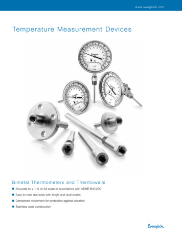
Temperature Measurement Deviceswww.swagelok.com1Te mpe rature Me asure me nt Device sB imetal T he r momete r s a nd T he r mowe lls Easy-to-read dial sizes with single and dual scales Dampened movement for protection against vibration Stainless steel constructionTHERMOMETERS /THERMOWELLS Accurate to 1 % of full scale in accordance with ASME B40.200
2Measurement DevicesContentsDampened-MovementBimetal ThermometersFeatures . . . . . . . . . . . . . . . . . . . . 2Technical Data . . . . . . . . . . . . . . . 2Materials of Construction . . . . . . 2Testing . . . . . . . . . . . . . . . . . . . . . 2Dimensions . . . . . . . . . . . . . . . . . 3Ordering Information . . . . . . . . . . 3ThermowellsFeatures . . . . . . . . . . . . . . . . . . . . 4Dampened-Movement Bimetal ThermometersSwagelok thermometers are actuated by a bimetal helixcoil. Silicone-free gel dampens vibration effects, and casesare hermetically sealed in accordance with ASME B40.200 toprevent fogging and moisture damage to internal components.Features Glass, polycarbonate, and safety-glass lenses to meet applicationrequirements All-welded 304 stainless steelconstruction standard; 316 stainlesssteel process connection and stemavailable Adjustable-angle, center-back,and lower-back mount processconnectionsTechnical Data . . . . . . . . . . . . . . . 4 External adjustment for fieldDimensions . . . . . . . . . . . . . . . . . 4calibration 50 % over- and under-rangeprotection against damage to internalcomponents up to 500 F (260 C)Ordering Information . . . . . . . . . . 6Thermowell TeesTTW Series Thermowell Tees. . . . 7 Anti-parallax dial for easy readingTechnical DataDialStem Temperature measurement ranges: Stem is welded at tip and process –100 to 150 through 200 to 1000 F –70 to 70 C through 100 to 540 C.Case Stem angle adjusts more than 180 ;case rotates 360 .connection. Temperature-sensing bimetal helixis carefully sized and tested, heattreated, and aged to relieve inherentstresses and ensure continuedaccuracy. Maximum ambient operatingtemperature 200 F (93 C)Materials of ConstructionComponentMaterialStem304 SSCase, bezel,staff rod,bellows, bracket,screws304 SSAdjustment screw303 SSO-ringEPDMDial, pointerAluminumTHERMOMETERS /THERMOWELLSBimetal elementDampeningmediaVaries withtemperature rangeSilicone-freeinert gelLens gasketNeoprene (dial ranges500 F [260 C] and under);EPDM (dial ranges over500 F [260 C])LensGlass, polycarbonate,or safety glassWetted components listed in italics.TestingEvery Swagelok dampened-movementbimetal thermometer is factorycalibrated to meet ASME B40.200.
Temperature Measurement Devices3Dampened-Movement Bimetal ThermometersDimensions1.50Dimensions, in inches (millimeters), are for reference only and are subject to change.0.941/4 in. hexadjustment(23.9)B(38.0)2.52(64.0)1/4 in. hexadjustment0.251/4 in. hexadjustment(6.4)BC2.64(67)Astem length1.46(37.0)Center ofrotationCenter-Back MountDialSizein. (mm)DAstemlengthDimensions, in. (mm)ABCAdjustable-Angle Mount3 (76.2) 2.5 (63.5), 4 (102), 6 (152), 3.25 (82.6) 3.00 (76.2)9 (229), or 12 (305)5 (127)5.25 (133) 5.00 (127)Center-Back Mount3 (76.2) 2.5 (63.5), 4 (102), 6 (152), 3.25 (82.6) 3.00 (76.2)9 (229), or 12 (305)5 (127)5.25 (133) 5.00 eMount—Lower-Back Mount3 (76.2) 2.5 (63.5), 4 (102), 6 (152), 3.25 (82.6) 3.00 (76.2) 3.31 (84)9 (229), or 12 (305)5 (127)5.25 (133) 5.00 (127) 4.29 (109)0.25(6.4)Lower-BackMountOrdering InformationBuild a dampened-movement bimetal thermometer ordering number by combining the designators in the sequence shown below.1234567T48A - 025 - FS - 01 - G - 8 - NT1 Dial Size, MountingT48A 3 in. (76.2 mm), adjustable angleT48C 3 in. (76.2 mm), center backT48L 3 in. (76.2 mm), lower backT80A 5 in. (127 mm), adjustable angleT80C 5 in. (127 mm), center backT80L 5 in. (127 mm), lower back2 Stem Length 2.5 in. (63.5 mm)4 in. (102 mm)6 in. (152 mm)9 in. (229 mm)12 in. (305 mm)3 ScaleCS CelsiusDS Dual Fahrenheit (primary) andCelsius (secondary)FS Fahrenheit5 Lens MaterialG Glass (standard)P PolycarbonateS Laminated safety glassSee below.Dial RangesFahrenheit( F)Celsius( C)–100 to 150–70 to 7001–40 to 160–40 to 70190 to 200–15 to 90050 to 250–20 to 1200650 to 30010 to 1500850 to 55010 to 29016➀150 to 75065 to 40011➀200 to 1000100 to 540Designator12➀➁➀ Dial range not available with silicone liquid fill.➁ Not recommended for continuous use over800 F (426 C).6 Process Connection8 1/2 in. male NPT9 Male G1/2B7 OptionsND No dampeningNT NIST-traceable calibrationcertificateSF Silicone liquid fill (not availablewith standard dampening, withglass lens options, or for dialranges over 500 F [260 C])SS 316 stainless steel processconnection and stemUN NPT union lock nutTHERMOMETERS /THERMOWELLS0250400600901204 Dial Range
4Measurement DevicesThermowellsThermowells are recommended toprotect Swagelok dampened-movementbimetal thermometers from damagethat could result from contact withpressurized, corrosive, flowing, viscous,or abrasive process fluids. They alsoenable removal of thermometers forreplacement or service without affectingthe process or system.DimensionsDimensions, in inches (millimeters), are for reference only and are subject to change.The U dimension is the depth the thermowell is inserted into the fluid system and isspecified in the ordering number. See Ordering Information, page 6.Threaded (TWT) Process Connection1/2 in.NPSMUinsertion depthB2.50(63.5)D1 1/8 in. hexCAstem length0.26 (6.6)0.25(6.4)Lag and Reduced Shank ShownDimensions, in. (mm)Features 304 stainless steel constructionstandard; 316 stainless steelavailable Accommodate 2.5 through 12 in.(63.5 through 305 mm) thermometerstem lengths in reduced-, straight-,and tapered-shank configurations Available with lag extensions for useB1/2 in. SizeACDStemNo WithLength Lag LagRSTRST2.5 (63.5)0.50———4 (102)(12.7)1.75 3.750.620.50 0.626 (152)(44.4) (95.2) 0.62 (15.7) 0.62 (12.7) (15.7) 0.50(15.7)(12.7)9 (229)4.75 (15.7)12 (305)(121)3/4 in. SizeCR0.50SDTRST—(12.7)—0.620.50 0.620.75 (15.7) 088 (12.7) (15.7) 0.62(19.0)(22.4)(15.7)R denotes reduced shank; S denotes straight shank; T denotes tapered shank.in insulated piping applicationsTechnical DataInstrument Connection1 2 in. female NPSM straight pipethread for mechanical joints standard;female G1/2B connection availableProcess ConnectionKwik-Clamp (TWS) Process Connection1/2 in.NPSMUinsertion depthB1.05D(26.7)C ASME B16.5 raised-face flange0.250.26 (6.6)(6.4)Astem length 3-A–compliant sanitary Kwik-Clamp Threaded (NPT)No Lag and Straight Shank Shown Weld socketDimensions, in. (mm)AStemLengthBTHERMOMETERS /THERMOWELLS4 (102)6 (152)9 (229)12 (305)CNo Lag With .4)(121)R denotes reduced shank; S denotes straight shank; T denotes tapered shank.0.62(15.7)
Temperature Measurement Devices5ThermowellsDimensionsDimensions, in inches (millimeters), are for reference only and are subject to change.The U dimension is the depth the thermowell is inserted into the fluid system and is specified in the ordering number.See Ordering Information, page 6.Raised-Face Flange (TWF) Process ConnectionBFlange DimensionsUinsertion depthC dia,D numberof holesB1/2 ME Class 150Astem lengthNominalFlangeSizein.No Lag and Reduced Shank ShownDimensions, in. (mm)AStemLengthBCNo Lag With Lag4 (102)DRST0.880.75(22.4)(19.0)—6 (152)2.259 (229)12 (305)(57.2)1RS0.500.75(12.7)(19.0)—4.25 (108)5.25 (133)—0.88(22.4)0.62(15.7)2Weld Socket (TWW) Process Connection1Uinsertion depthB1 1/2E2D0.26 ingHolesD4ASME Class 300NominalFlangeSizein.R denotes reduced shank; S denotes straight shank; T denotes tapered shank.1/2 in.NPSM1 1/2TDimensionsin. (mm)Dimensionsin. HolesD4480.25(6.4)Astem lengthNo Lag and Tapered Shank Shown Dimensions, in. (mm)BWithLag1.753.754 (102)6 (152)9 (229)12 .7)(19.0)0.88(22.4)ET3/4 in.Size—0.500.75(12.7)(19.0)(121)R denotes reduced shank; S denotes straight shank; T denotes tapered shank.0.62(15.7)1 in.Size—1.05(26.7)1.35(34.3)THERMOMETERS /THERMOWELLSAStemLengthQualified personnel shouldperform welding.
6Measurement DevicesThermowellsOrdering InformationBuild a thermowell ordering number by combining the designators in the sequence shown below.1234567TWF - 110 - R - 1 - L - 2.00 - CS1 Process ConnectionTWFTWSTWTTWW ASME B16.5 raised-face flange Sanitary clamp Threaded Weld socket2 Process Connection SizeTWF Process Connection110 1 in. ASME class 150115 1 1/2 in. ASME class 150120 2 in. ASME class 150310 1 in. ASME class 300315 1 1/2 in. ASME class 300320 2 in. ASME class 300TWS Process ConnectionC15 1 1/2 in. Kwik-ClampC20 2 in. Kwik-ClampTWT Process Connection008 1/2 in. male NPT012 3/4 in. male NPTTWW Process ConnectionP12 3/4 in. pipeP16 1 in. pipe3 ShankR ReducedS StraightT Tapered➀➀ Tapered shanks are not available for thermowellswith U dimensions of 4.00 in. (102 mm) or less.4 Bore Diameter1 0.260 in. (6.6 mm)5 Lag ExtensionL Lag extension➀N No lag extension➀ Not available for thermometer stems less thanTHERMOMETERS /THERMOWELLS6 in. (152 mm) long. Lag is 2 in. (50.8 mm) for6 in. (152 mm) thermometer stems and 3 in.(76.2 mm) for thermometer stems longer than6 in. (152 mm).6 U DimensionConnections with Lag ExtensionsTWF Process Connection2.00 2.00 in. (50.8 mm) (6 in. stem)4.00 4.00 in. (102 mm) (9 in. stem)7.00 7.00 in. (178 mm) (12 in. stem)TWS and TWW Process Connections2.50 2.50 in. (63.5 mm) (6 in. stem)4.50 4.50 in. (114 mm) (9 in. stem)7.50 7.50 in. (190 mm) (12 in. stem)TWT Process Connection2.50 2.50 in. (63.5 mm) (6 in. stem)4.50 4.50 in. (114 mm) (9 in. stem)7.50 7.50 in. (190 mm) (12 in. stem)Connections with No Lag ExtensionsTWF Process Connection2.00 2.00 in. (50.8 mm) (4 in. stem)4.00 4.00 in. (102 mm) (6 in. stem)7.00 7.00 in. (178 mm) (9 in. stem)10.0 10.0 in. (254 mm) (12 in. stem)TWS and TWW Process Connections2.50 2.50 in. (63.5 mm) (4 in. stem)4.50 4.50 in. (114 mm) (6 in. stem)7.50 7.50 in. (190 mm) (9 in. stem)10.5 10.5 in. (267 mm) (12 in. stem)TWT Process Connection1.00 1.00 in. (25.4 mm) (2.5 in. stem,1/2 in. connection)1.63 1.63 in. (41.4 mm) (2.5 in. stem,3/4 in. connection)2.50 2.50 in. (63.5 mm) (4 in. stem)4.50 4.50 in. (114 mm) (6 in. stem)7.50 7.50 in. (190 mm) (9 in. stem)10.5 10.5 in. (267 mm) (12 in. stem)7 OptionsCS Protective stainless steel capand chainG1 Female G1/2B instrumentconnectionSS 316 stainless steel material
Temperature Measurement Devices7TTW Series Thermowell TeesThermowells are recommended toprotect thermometers from damagethat could result from contact withpressurized, corrosive, flowing, viscous,or abrasive process fluids. They alsoenable removal of thermometers forreplacement or service without affectingthe process.Features 316 stainless steel construction Seal-welded connection between teeand thermowell Instrument connection: 1/2 in. femaleNPSM straight pipe threads Instrument stem length: 2.5 in(63.5 mm)Ordering InformationSelect an ordering number. Dimensions, in inches (millimeters), are for reference only and are subject to change.End ConnectionsPort 1Port 2Swagelok TubeFittingsMaleNPTFemaleNPTFemale NPTSizeStraight PatternOrdering Number3/8 in.SS-TTW-S61/2 in.SS-TTW-S85/8 in.SS-TTW-S103/4 in.SS-TTW-S121 in.SS-TTW-S1612 mmAngle PatternOrdering Number—Dimensions, in. (mm)AAxAyBPressure Ratingpsig (bar)0.28 (7.1)4900 (337)3.06 (77.7) 1.53 (38.9) 1.53 (38.9) 2.86 (72.7) 0.41 (10.4)4900 (337)3.06 (77.7) 1.53 (38.9) 1.53 (38.9) 2.86 (72.7) 0.50 (12.7)4900 (337)SS-TTW-S12-A3.52 (89.4) 1.76 (44.7) 1.76 (44.7) 2.96 (75.2) 0.62 (15.7)4600 (316)SS-TTW-S16-A3.86 (98.0) 1.93 (49.0) 1.93 (49.0) 2.96 (75.2) 0.88 (22.4)4600 (316)SS-TTW-S12MMSS-TTW-S12MM-A3.06 (77.7) 1.53 (38.9) 1.53 (38.9) 2.86 (72.7)0.37 (9.5)4900 (337)16 mmSS-TTW-S16MMSS-TTW-S16MM-A3.06 (77.7) 1.53 (38.9) 1.53 (38.9) 2.86 (72.7) 0.50 (12.7)4900 (337)18 mmSS-TTW-S18MMSS-TTW-S18MM-A3.52 (89.4) 1.76 (44.7) 1.76 (44.7) 2.96 (75.2) 0.59 (15.0)4600 (316)1/2 in.SS-TTW-M8-F8SS-TTW-M8-F8-A3.12 (79.2) 1.56 (39.6) 1.56 (39.6) 2.93 (74.4) 0.47 (11.9)5600 (385)3/4 in.SS-TTW-M12-F12SS-TTW-M12-F12-A3.59 (91.2) 1.92 (48.8) 1.67 (42.4) 3.26 (82.7) 0.62 (15.7)5100 (351)1/2 in.SS-TTW-F8SS-TTW-F8-A3.12 (79.2) 1.56 (39.6) 1.56 (39.6) 2.93 (74.4) 0.94 (23.9)5600 (385)3/4 in.SS-TTW-F12SS-TTW-F12-A3.84 (97.5) 1.92 (48.8) 1.92 (48.8) 3.26 (82.7) 1.17 (29.7)5100 (351)SS-TTW-S8-A—2.84 (72.1) 1.42 (36.1) 1.42 (36.1) 2.86 (72.7)E1/2 in. NPSMAAx1/2 in. NPSM1 1/8 in.hex1 1/8 in.hexWeld2.50 (63.5)StraightPatternWeldBBAnglePatternPort 2 AyPort 1Port 1EPort 2AxMS-02-353, RevF, June 2020THERMOMETERS /THERMOWELLSE
IntroductionSince 1947, Swagelok has designed, developed, and manufactured high-quality,general-purpose and specialty fluid system products to meet the evolving needs ofglobal industries. Our focus is on understanding our customers’ needs, finding timelysolutions, and adding value with our products and services.We are pleased to provide this global edition of the book-bound Swagelok ProductCatalog, which compiles more than 100 separate product catalogs, technical bulletins,and reference documents into one convenient, easy-to-use volume. Each productcatalog is up to date at the time of printing, with its revision number shown on the lastpage of the individual catalog. Subsequent revisions will supersede the printed versionand will be posted on the Swagelok website and in the Swagelok electronic DesktopTechnical Reference (eDTR) tool.For more information, visit your Swagelok website or conta
calibrated to meet ASME B40.200. Materials of Construction Component Material Stem 304 SS Case, bezel, staff rod, bellows, bracket, screws 304 SS Adjustment screw 303 SS O-ring EPDM Dial, pointer Aluminum Bimetal element Varies with temperature range Dampening media Silicone-free inert gel Lens gasket Neoprene (dial ranges 500 F [260 C] and under); EPDM (dial ranges over 500 F [260 C .