Transcription
www.swagelok.comThread andEnd ConnectionIdentification Guide
2
INTRODUCTIONContents45Step-by-Step IdentificationProcedure for Threadsand End Connections . . . . . . . . . . . . . . .6Thread IdentificationReference Tables . . . . . . . . . . . . . . . . . . .12Tapered Threads . . . . . . . . . . . . . . . . . . . .20TABLESThread and End Connection Terminology . . .General Terminology . . . . . . . . . . . . . . . . . . .IDENTIFICATIONIntroductionStraight Threads . . . . . . . . . . . . . . . . . . . .26End Connections That Use:Unified Screw Threads . . . . . . . . . . . . . . . . . .ISO 228/1 Threads . . . . . . . . . . . . . . . . . . . . .Metric (ISO 261) Threads . . . . . . . . . . . . . . . .NPSM Threads . . . . . . . . . . . . . . . . . . . . . . . .28354249TAPEREDEnd Connections That Use:Tapered Threads . . . . . . . . . . . . . . . . . . . . . . . 22AppendixSTRAIGHT50515253APPENDIXEnd Connection to Thread Matrix . . . . . . . . .Thread to End Connection Matrix . . . . . . . . .Thread Identification Tools . . . . . . . . . . . . . . .Glossary . . . . . . . . . . . . . . . . . . . . . . . . . . . . .3
INTRODUCTIONIntroductionThread andEnd Connection TerminologyStandards are used to help identify threads and endconnections. We will use the following definitions inthis manual:Thread StandardA specific reference to a formal standard (forexample, ASME B1.1, EN 10226-1, or ISO 261) thatdescribes thread form, including a thread’s angle,pitch, and diameter.End Connection StandardA specific reference to a national standard (suchas DIN 3852 or JIS R and JIS Rc) or industry groupstandard (such as SAE J512) that describes an endconnection’s components, seal area, geometry,and nominal sizes. Thread standards are usuallyreferenced in the end connection standard.Thread Standards andEnd Connection StandardsMany mechanical end connections have threads.Therefore, thread standards can be used to helpdefine end connection standards.PitchFor the purposes of this guide, pitch refers tothreads per inch, instead of the distance betweenthe threads, for fractional screw threads and pipethreads. For all metric screw threads, pitch refers tothe distance between adjacent threads.4
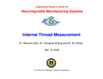
General terms and characteristics, which apply to allend connection threads, are shown below for bothmale and female threads.Threads1.2.3.4.4Thread flank angleTaper angleMale thread ODFemale thread ID671 235.6.7.8.CrestRootFlankPitch (metric)85MaleEnd Connections1. Body size2. Shoulder3. FaceFemale123End Connection5INTRODUCTIONGeneral Terminology
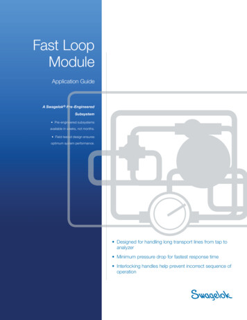
Step-by-Step IdentificationProcedure for Threadsand End ConnectionsIDENTIFICATIONStep 1: Determine if the thread is tapered orstraight (parallel).Step 2:Measure the thread diameter.Step 3:Determine the thread pitch.Step 4:Determine the thread standard.Step 5:Identify the end connection.Note: Even experienced workers sometimeshave difficulty identifying threads,regardless of their thread identificationprocedure and the quality of their gauges.DetailsStep 1: Determine if the thread isT tapered or S straight (parallel).Use a caliper to measure the nominal male or femalethread crest-to-crest diameter on the first, fourth,and last full threads (Fig. 1).TIf the diameters increase for a male end ordecrease for a female end, the thread is tapered.SIf all the diameters are the same, the thread isstraight (parallel).Last4th1stFig. 1Measuring Crest-to-Crest Thread Diameters6
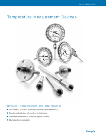
Last4th1stLast4thIDENTIFICATIONT1stSFig. 2Measuring the Thread DiametersStep 2: Measure the thread diameter.Use a caliper to measure the nominal male or femalethread diameter from crest-to-crest (Fig. 2).TMeasure the fourth or fifth full thread.SMeasure any full thread.The diameter measurement obtained in this stepmay not be exactly the same as the listed nominalsize for the given thread. The main reason for thisvariation is industry or manufacturing tolerances.Step 3: Determine the thread pitch.To determine the thread pitch, use the Swagelok pitch gauges and check the thread against eachform until you find a match. If you prefer to narrowdown the choices, use the following procedure:a.On the appropriate thread identification referencetable, locate the nominal thread diameter. Notethat it is common to have the thread diameter fordifferent threads listed multiple times.TTurn to the Tapered Thread IdentificationReference Tables beginning on page 12.STurn to the Straight Thread IdentificationReference Tables beginning on page 14.7
For each case, read across the table to thepitch column to determine the possible threadpitches for your thread.c.Try the appropriate pitch gauge form for thethreads identified in Step b. above until you finda match (Fig. 3).IDENTIFICATIONb.1.5 mm perthread18 threadsper inchNo MatchMatchFig. 3.Determining the Thread PitchStep 4: Determine the thread standard.Once you have determined the following abouta thread, you have all the information required toidentify it: Male or female Straight or tapered Nominal male or female diameter PitchNow, turn to the appropriate thread identificationreference table and identify the thread.Step 5: Identify the end connection.TIf the thread is tapered:a.Locate the end connections that have thetapered thread you identified. (See pages 20through 25.)b.Study the cross-section drawings for these endconnections and determine which one matchesyour end connection.8
If the thread is straight:a.Locate the end connections that use thestraight thread you identified. (See pages 26through 49.)b.Study the cross-section drawings for these endconnections and determine which one matchesyour end connection.Note: The Swagelok combination seat andpitch gauge set includes 45 , 37 , and30 seat angle gauges to assist with endconnection identification. (See page 52.)c.Select one of the gauges and place its angleagainst the seat angle of the end connection.d.If the center line of the fitting and the longitudinalaxis of the gauge are parallel, the seat angle andthe gauge angle are the same. If not, try anothergauge.Longitudinal axisCenter lineNo MatchSeat angleSeat gauge angleMatchFig. 4Determining Seat AngleNote: Fittings have seat angles other than 45 ,37 , and 30 . Contact your authorizedSwagelok sales and service representativefor additional information.9IDENTIFICATIONS
EXAMPLE:Thread and End ConnectionIdentification (Steps 1 to 5)IDENTIFICATIONYou have a male fitting and you need to identifyits thread.Step 1: Determine if the thread is taperedor straight (parallel).You find that the thread is straight.Step 2:Measure the thread diameter.You find the thread diameter to be 0.430 in.Step 3:a.Determine the thread pitch.Because the thread is straight, turn to theStraight Thread Identification ReferenceTable, page 14, and locate the threaddiameter. See section of table below.NominalThreadSize Designation3/87/161/2Nominal MaleThread Diameterin.mmPitch➀Page29 to 34UNF0.375 to 0.3639.53 to 9.2224UNPSM0.65816.7118U50ISO 228/10.65616.6619W35 to 42UNS0.436 to 0.429 11.07 to 10.9024U29 to 34UNF0.436 to 0.424 11.07 to 10.7720U29 to 34UNF0.500 to 0.487 12.70 to 12.3620U29 to 34NPSM0.81820.7814U50ISO 228/10.82520.9614W35 to 42➀ U Unified W Whitworth M MetricLabeling on each Swagelok pitch gauge formb.Look across the table to find thecorresponding pitches. In this case, theyare 20 and 24.c.Therefore, to determine the pitch of the threadyou would use your 20 and 24 pitch gauges.For the purposes of this example, assume thatthe pitch is 24.10
IDENTIFICATIONStep 4: Determine the thread standard.At this point you know that the thread has thefollowing characteristics:a. Maleb. Straightc.Nominal thread diameter of 0.430 in.d.Pitch equals 24Looking at the cut-out portion of the straightthread identification reference table, you see thatthe only thread with all of these characteristics isa 7/16 in. UNS thread.Step 5: Identify the end connection.So far you know that you have a 7/16 in. UNSthread. To identify the end connection, you:a.Identify the type of seal.b.Turn to the End Connections That UseUnified Screw Threads section in thismanual (pages 28 through 34), andfind the configuration that matches yourend connection.11
Thread IdentificationReference TablesTapered—MaleTNote: Measured thread diameters may not match tablemeasurements exactly. All threads have tolerancesregarding many parts of the threads. The information inthis table is not intended to be used as inspection criteriafor threaded fittings. It is intended to be used as a guide tohelp identify various threads.NominalThreadSize, in. Designation1/16TABLES1/81/43/81/23/411 1/41 1/22Nominal MaleThread Diameterin.mmPitch➀ISO 7/10.3047.7228W25NPT0.3087.8427U23 to 24ISO 7/10.3839.7328W25NPT0.40110.1827U23 to 24ISO 7/10.51813.1619W25NPT0.53313.5418U23 to 24ISO 7/10.65616.8619W25NPT0.66816.9818U23 to 24ISO 7/10.82520.9614W25NPT0.83221.1414U23 to 24ISO 7/11.04126.4414W25NPT1.04326.4914U23 to 2423 to 24PageNPT1.30533.1411.5UISO 7/11.30933.2511W25NPT1.64941.9011.5U23 to 24ISO 7/11.65041.9111W25ISO 7/11.88247.8011W25NPT1.88847.9711.5U23 to 24ISO 7/12.34759.6111W25NPT2.36260.0011.5U23 to 24➀ U UnifiedW WhitworthLabeling on each Swagelok pitch gauge formM MetricNote: 1/2 and 3/4 in. ISO 7/1 and NPT threads can be difficultto identify because they are very close in design. Positiveidentification may not be possible without the use of anoptical comparator. Contact your authorized Swagelokrepresentative for additional information.12
Tapered—FemaleTNote: Measured thread diameters may not match tablemeasurements exactly. All threads have tolerancesregarding many parts of the threads. The information inthis table is not intended to be used as inspection criteriafor threaded fittings. It is intended to be used as a guide tohelp identify various threads.1/161/81/43/81/23/411 1/41 1/22 1/4Nominal FemaleThread Diameterin.mmPitch➀PageNPT0.2446.2227U23 to 24ISO 7/10.2586.5628W25NPT0.3368.5427U23 to 24ISO 7/10.3378.5728W25NPT0.43611.0718U23 to 24ISO 7/10.45111.4519W25NPT0.57114.4918U23 to 24ISO 7/10.58914.9519W25NPT0.70517.9014U23 to 24ISO 7/10.73418.6314W25NPT0.91423.2114U23 to 24ISO 7/10.94924.1214W25NPT1.14829.1511.5U25ISO 7/11.19330.2911W23 to 2423 to 24NPT1.49137.8711.5UISO 7/11.53438.9511W25NPT1.73043.4911.5U23 to 24ISO 7/11.76644.8511W25NPT2.20355.9511.5U23 to 24ISO 7/12.23156.6611W25➀ U UnifiedW WhitworthLabeling on each Swagelok pitch gauge formM MetricNote: 1/2 and 3/4 in. ISO 7/1 and NPT threads can be difficultto identify because they are very close in design. Positiveidentification may not be possible without the use of anoptical comparator. Contact your authorized Swagelokrepresentative for additional information.13TABLESNominalThreadSize, in. Designation
Straight—MaleSNote: Measured thread diameters may not match tablemeasurements exactly. All threads have tolerancesregarding many parts of the threads. The information inthis table is not intended to be used as inspection criteriafor threaded fittings. It is intended to be used as a guide tohelp identify various threads.NominalThreadSize DesignationNominal MaleThread Diameterin.mmPitch➀PageISO 228/10.3047.7228W35 to 41ISO 228/10.3839.7328W35 to 41NPSM0.39410.0127U49ISO 228/10.51813.1619W35 to 410.52213.26Fractional, 9 to 34UN0.313 to 0.305 7.95 to 7.7528U29 to 340.375 to 0.363 9.53 to 9.2224U29 to 34NPSM0.65816.7118U49ISO 228/10.65616.6619W35 to 41UNS0.436 to 0.429 11.07 to 10.9024U29 to 34UNF0.436 to 0.424 11.07 to 10.7720U29 to 34UNF0.500 to 0.487 12.70 to 12.3620U29 to 34NPSM0.81820.7814U49ISO 228/10.82520.9614W35 to 41UNF0.563 to 0.548 14.29 to 13.9218U29 to 34UNF0.625 to 0.611 15.88 to 15.5218U29 to 34ISO 228/1UN0.90222.910.688 to 0.677 17.46 to 17.1914W35 to 4116U29 to 34UNS0.749 to 0.740 19.02 to 18.8018U29 to 34UNF0.750 to 0.734 19.05 to 18.6516U29 to 34NPSM1.02926.1414U49ISO 228/11.04126.4414W35 to 4113/167/818U24UUNF11/163/40.313 to 0.301 7.95 to 7.77UN0.813 to 0.802 20.64 to 20.3616U29 to 34UNF0.875 to 0.858 22.23 to 21.7914U29 to 34UNS0.874 to 0.865 22.20 to 21.9718U29 to 3414W35 to 41ISO 228/1➀ U Unified1.18930.20W WhitworthM MetricLabeling on each Swagelok pitch gauge form(continued on next page)14
Straight—MaleSNominalThreadSize DesignationNominal MaleThread Diameterin.mmPitch➀Page14U29 to 34Fractional, in.1.000 to 0.983 25.40 to 24.97NPSM1.28732.6911.5U49ISO 228/11.30933.2511W35 to 411 1/16UN1.063 to 1.049 27.00 to 26.64 12, 14U 29 to 34UN1.063 to 1.051 27.00 to 26.701.49237.9016U29 to 341 1/8ISO 228/111W1 3/16UN1.188 to 1.174 30.16 to 29.8335 to 4112U29 to 34UNF1.250 to 1.231 31.75 to 31.571 1/4NPSM1.63241.4511.5U12U29 to 3449ISO 228/11.65041.9111W35 to 411 5/16UN1.313 to 1.299 33.34 to 33.0012U29 to 341 3/8UNF1.375 to 1.356 34.93 to 34.4412U29 to 34UN1.438 to 1.424 36.51 to 36.1812U29 to 341 7/161 1/2NPSM1.87147.5211.5U49ISO 228/11.88247.8011W35 to 411 5/8UN1.625 to 1.612 41.28 to 40.94 12, 20U 29 to 341 11/16UN1.688 to 1.674 42.86 to 42.531 3/4ISO 228/11 7/8UN1.875 to 1.862 47.63 to 47.29UN2.000 to 1.987 50.80 to 50.462ISO 228/12.34759.61NPSM2.34559.5611.5U4912U29 to 342 1/2UN2.11653.752.500 to 2.487 63.50 to 63.1612U29 to 3411W35 to 4112U29 to 3412U29 to 3411W35 to 41Metric, mm80.3107.881.0M42 to 48100.3899.881.0M42 to 4812Metric0.46711.851.5M42 to 480.46811.881.0M42 to 48140.54513.851.5M42 to 48160.62415.851.5M42 to 48180.70317.851.5M42 to 48➀ U UnifiedW WhitworthM MetricLabeling on each Swagelok pitch gauge form(continued on next page)15TABLESUNS1
Straight—MaleSNominalThreadSize DesignationNominal MaleThread Diameterin.mmPitch➀PageMetric, 261.01825.851.5M2730TABLES333638Metric394245
Note: 1/2 and 3/4 in . ISO 7/1 and NPT threads can be difficult to identify because they are very close in design . Positive identification may not be possible without the use of an optical comparator . Contact your authorized Swagelok representative for additional information . Nominal Thread Size, in. Designation Nominal Male Thread Diameter