Transcription
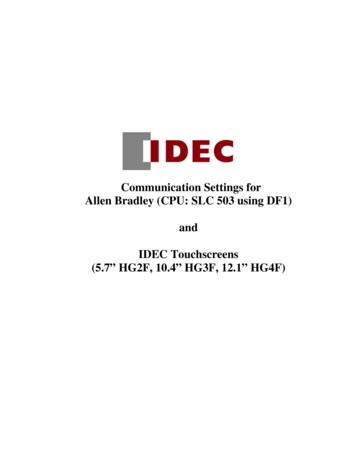
Allen-Bradley Stratix 5700 Network Address Translation (NAT)Mark Devonshire – Product Manager, Rockwell AutomationMark Hantel – Senior Engineer, Rockwell AutomationSynopsisMachine integration onto a plant’s network architecture can be difficult as OEMIP-address assignments rarely match those of the end-user network and networkIP addresses are generally unknown until the machine is being installed – addingcost and time to the commissioning of the equipment, and delays moving thatequipment into production.The Allen-Bradley Stratix 5700 with Network Address Translation (NAT) is a hardwareLayer 2 implementation that provides “wire speed” 1:1 translations ideal forautomation applications where performance is critical.NAT allows for: High performance and simplified integration of IP-address mapping from a set of local, machine-level IP addresses to theend user’s broader plant network OEMs to deliver standard machines to end users without programming unique IP addresses End users to more simply integrate the machines into the larger network Easier machine maintenance because machine configuration remains standardThe Stratix 5700 switch with NAT technology also allows users to have the flexibility to segment or isolate network traffic bydetermining which devices are exposed to the larger network. By limiting access to certain devices, they can be isolated fromunneeded network traffic, which can help optimize network performance at the local level.Line ControllerStratix 83007B0A1B1Z0Z102 sNC NCCOM COM V VDANGER0809101112131415V VOUT OUT0 0 V VOUT OUT0 0 V VOUT OUT0 0 V VOUT OUT0 0 V9DANGERV VOUT OUT0 0 V VOUT OUT0 0 I IOUT OUT0 0 COM COM192.168.1.3192.168.1.400:00:BC:66:0F:C7BRAKE/DC BUS192.168.1.5345611 12 13 144571523671011 12 13 1415A0B0A1B1Z0Z102 FUSE13ModuleStatusCNetworkActivityOKA0 AoB0 B0Z0 Z0A1 A1B1 B1Z1 Z1 V -VCOM COM01OUT OUT02OUT OUT13NC NCCOM COM V V24VDCINPUTVCOM OUT0 21019ABNetworkStatusCOM OUT0 192.168.1.21800010203040506070809101112131415COM COM01DEPoint BusStatusMEM3501734-AENTSystemPowerFieldPowerV VOUT OUT0 0 V VOUT OUT0 0 V VOUT OUT0 0 V VOUT OUT0 0 VA ENABLEB REGENC DATA ENTRYD FAULTE COM ACTIVITY24VDCINPUTCOM OUT0 VCOM OUT0 MORTOR FEEDBACK0001020304050607COM COM01MORTOR FEEDBACK00:00:BC:66:0F:C7FieldPowerA ENABLEB REGENC DATA ENTRYD FAULTE COM ACTIVITYETHERNETOUT OUT02OUT OUT1300800 0801 0902 1003 1104 1205 1306 1407 15MEM3501734-AENTETHERNETCOM COM01DEPoint BusStatusSystemPowerINA0A0 AoB0 B0Z0 Z0A1 A1B1 B1Z1 Z1 V -VDCINPUT71515NAT Translation192.168.1.2 10.10.10. 3OUT6624VDCSINK\SOURCE55HIGH SPEEDCOUNTER4DCOUTPUT4311 12 13 1400 0801 0902 1003 1104 1205 1306 1407 15MACHINE 224VDCSOURCE311 12 13 142IN21010DCINPUT919NAT Translation192.168.1.2 10.10.10. 2OUT18HIGH MACHINE 1V VOUT OUT0 0 V VOUT OUT0 0 I IOUT OUT0 0 COM COM192.168.1.2Figure 1 - Multiple Identical Machines On The Same Network192.168.1.3192.168.1.4BRAKE/DC BUS192.168.1.5
2 Stratix 5700 NAT WhitepaperWhat Is NAT?Network Address Translation is a service that can translate a packet from one IP addressto another IP address. NAT can be found either on a Layer 2 device or on a Layer 3 device.NAT can be understood easiest with the introduction of the concept of a private networkand a public network (Figure 2)*. These two networks are separated by a boundary;a device that implements NAT is this boundary. NAT can take on multiple forms includingone-to-many NAT and one-to-one NAT (our implementation).Public Subnet(Example: 10.0.0.X)Public Subnet(Example: 10.0.0.X)One Public IP AddressNAT Enabled DeviceNAT Enabled DeviceMany Private IP Addresses( ne pper(oer connected de(onedevice)Private Subnet(Example: 192.168.1.X)Private Subnet(Example: 192.168.1.X)Figure 2 – Concept Of Public And PrivateSubnets With A NAT Device SeparatingFigure 3 – One-To-Many NAT ExampleOne-to-many NAT is also known as Port Address Translation and allows one public IPaddress to be shared by many private IP addresses. This function is commonly found inconsumer grade routers. A one-to-many NAT device contains a table that allows uniqueprivate host ports to be exposed on the single public IP address (Figure 3).What is One-To-One NAT?One-to-one (1:1) NAT is a service that allows the assignment of a unique public IP addressto an existing private IP address (end device), allowing the end device to communicateon both subnets (Figure 4). This service is configured in a NAT enabled device and is thepublic “alias” of the IP address physically programmed on the end device. This is typicallyrepresented by a table in the NAT device.Public Subnet(Example: 10.0.0.X)Many Public IP Addresses (one per device wishingto be accessible from the Public Subnet)NAT Enabled DeviceMany Private IP Addresses( ne pper(oer connected de(onedevice)Private Subnet(Example: 192.168.1.X)Figure 4 – 1:1 NAT Example Note that we use the terms private and public to differentiate the two networks on either side of the NAT device.This does not infer that the public network must be Internet routable
Stratix 5700 NAT Whitepaper 31:1 NAT allows a manufacturer to keep duplicate machines identical while providing aunique identity (alias) to the larger industrial network. The feature also gives a granularmethod of granting or restricting access to an end device (I/O blocks, drives, etc.) on themachine in one place.1:1 NAT works by replacing the IP header on a packet and recalculating the packetchecksums as it finds the appropriate match in the NAT table when it passes throughthe NAT device (Figure 5).Figure 5 – NAT Specific Data in an Ethernet Packet1:1 Layer 2 vs. Layer 3 NATHistorically 1:1 NAT has been implemented in software on Layer 3, meaning the NATenabled device acts as the default gateway (router) for all the devices on the privatesubnet. The NAT device will intercept traffic on behalf of its private subnet devices,perform the translation, and route traffic to the private subnet appropriately. As a softwareimplementation, Layer 3 NAT translations typically are handled by the host CPU on the NATdevice. Performance of a software NAT implementation is tied directly to the loading thehost CPU can handle.The Layer 2 1:1 NAT implementation differs in several areas. Rather than acting as thedefault gateway for the private subnet, Layer 2 NAT has two translation tables whereprivate-to-public and public-to-private subnet translations can be defined. Layer 2 NATis a hardware-based implementation that provides wire speed performance throughoutswitch loading. This implementation also supports multiple VLANs through the NATboundary for enhanced network segmentation. Ring architecture support is built intoLayer 2 NAT, allowing redundancy through the NAT boundary.
4 Stratix 5700 NAT WhitepaperStratix 5700 1:1 Layer 2 NAT ImplementationThe Stratix 5700 integrates 1:1 NAT capability into the switch. This is a Layer 2 (MAC layer)implementation and is integrated with the hardware fabric of the switch (Figure 6).It allows for a scalable, high performance, single box solution.Uplink 1SStratixtraatix 5757007700000Uplink 2 (Optional)NATController (C1)192.168.1.10 (M1)10.10.1.10 (Public)192.168.1.30 (M2)SwitchDownlink PortsFigure 6 – NAT Block DiagramThe NAT feature is integrated in hardware between the uplink ports and the rest of theswitch. It supports one or two uplinks which can be used in star, redundant star and ringtopologies. One uplink would be used for a standard star topology. Two uplinks could beused for either a redundant star using spanning tree, or a ring topology using REP (Figure 7).Line ControllerCable BreakStratix 8300REP7A0B0A1B1Z0Z102 sNC NCCOM COMV VOUT OUT0 0 V VOUT OUT0 0 V VOUT OUT0 0 V VOUT OUT0 0 AKE/DC BUS192.168.1.5Figure 7 – REP Ring Topology345611 12 13 144571523671011 12 13 1415A0B0A1B1Z0Z102 FUSE13ModuleStatusCNetworkActivityOKA0 AoB0 B0Z0 Z0A1 A1B1 B1Z1 Z1 V -VCOM COM01OUT OUT02OUT OUT13ABNC NCCOM COM00 0801 0902 1003 1104 1205 1306 1407 15COM COM01DEPoint BusStatusMEM3501734-AENTSystemPowerFieldPowerV VOUT OUT0 0 V VOUT OUT0 0 V VOUT OUT0 0 V VOUT OUT0 0 VA ENABLEB REGENC DATA ENTRYD FAULTE COM ACTIVITY24VDCINPUTCOM OUT0 VCOM OUT0 MORTOR FEEDBACKV VOUT OUT0 0 V VOUT OUT0 0 I IOUT OUT0 0 COM COM21019 V V24VDCINPUTVCOM OUT0 192.168.1.28NetworkStatusA ENABLEB REGENC DATA ENTRYD FAULTE COM ACTIVITYCOM OUT0 MORTOR FEEDBACK00 0801 0902 1003 1104 1205 1306 1407 15COM COM01FieldPower00800 0801 0902 1003 1104 1205 1306 1407 15MEM3501734-AENTSystemPowerETHERNETOUT OUT02OUT OUT13DEPoint BusStatusETHERNETCOM COM01 V VDANGER00:00:BC:66:0F:C7A0 AoB0 B0Z0 Z0A1 A1B1 B1Z1 Z1 V -VIN71515DCINPUT6624VDCSINK\SOURCE55NAT Translation192.168.1.2 10.10.11.2OUT4HIGH SPEEDCOUNTER4311 12 13 14DCOUTPUT311 12 13 14200 0801 0902 1003 1104 1205 1306 1407 15MACHINE 224VDCSOURCE21010IN9DCINPUT119NAT Translation192.168.1.2 10.10.10.2OUT8HIGH MACHINE 1V VOUT OUT0 0 V VOUT OUT0 0 I IOUT OUT0 0 COM COM192.168.1.2192.168.1.3192.168.1.4BRAKE/DC BUS192.168.1.5
Stratix 5700 NAT Whitepaper 5NAT InstancesThe software interface for NAT has been implemented using the concept of instances(Figure 8). Each instance contains a name, “Private to Public” NAT table, “Public to Private”NAT table, VLAN and interface association, specific packet fix-ups, and specific types oftraffic that can be blocked or passed through. Typically only one instance will be used;however, multiple instances can be supported to differentiate between different VLANconfigurations. NAT can be attached to one or many VLANs, but will not translate trafficacross VLANS (i.e. change a VLAN tag) or break other existing VLAN rules.Figure 8 – NAT InstancesNAT TablesAn important concept of the Layer 2 NAT implementation is how NAT interacts withprivate and public subnets (Figure 9). Each NAT instance has two tables, a “Private toPublic” table, and a “Public to Private” table. “Private” devices must be assigned a unique IPaddress in the “Private to Public” NAT table on the “public” subnet. Likewise “public” devicesmust be assigned unique IP addresses in the “Public to Private” NAT table on the “private”subnet. The implementer is responsible for defining these addresses. The addresses mustbe unique and unused on other attached devices and throughout the switch.Public SubnetUplink 1SStratixtraatix 5757007700000NATController (C1)192.168.1.10 (M1)10.10.1.10 (Public)192.168.1.30 (M2)SwitchDownlink PortsPrivate SubnetFigure 9 – Stratix 5700 NATUplink 2 (Optional)
6 Stratix 5700 NAT WhitepaperEach private subnet device that is expected to talk on the public subnet must havea “Private to Public” translation. However, not all private subnet devices must havetranslations. They can be kept behind the NAT barrier to increase security, decrease trafficon the uplink port, and conserve public address space.If the uplinks are connected to a Layer 3 switch or router, only one “Public to Private”translation must be used – the default gateway (Figure 10). If the uplinks are connected viaa Layer 2 switch to other devices on the public subnet, each public subnet device musthave a unique IP address in the “Public to Private” table.Figure 10 – NAT Private to Public Table (General Tab)Types Of TranslationsThere are three types of translations that can be defined: single, range and subnet.A single translation will have one private address and one public address. A range will havea starting private address, a starting public address and a number of entries (Figure 11).A subnet translation allows the definition of a Class “B” subnet (mask: 255.255.0.0), Class“C” subnet (mask: 255.255.255.0) or a fraction of a Class “C” subnet (Figure 12). A maximumnumber of 128 NAT entries can be created per switch. These entries can be defined in oneinstance or up to 128 separate instances. These entries can be of any type and are definedby the rules below (Table 1). Subnet translations will have a starting private address andpublic address that must be aligned on proper subnet boundaries (Table 2).Types of TranslationsNumber of Entries in NAT TableSingle1RangeQuantity of RangeSubnet1Table 1 – Number of NAT Table Entries Per Translation Type
Stratix 5700 NAT Whitepaper 7Figure 11 – Example of Translation TypesFigure 12 – Example of A Subnet DefinitionSubnet MaskNumber of .255.0.065535Table 2 – Subnet Translation DetailThe use of a subnet translation will allow for many more than 128 IP addresses to betranslated. For example the table shown in Figure 11 uses 12 NAT entries but provides75 actual translations.
8 Stratix 5700 NAT WhitepaperVLANsWhen configuring NAT, you can assign one or more VLANs to a NAT instance (Figure 13).When you assign a VLAN to a NAT instance, the traffic associated with that VLAN is subjectto the configuration parameters of the NAT instance. Configuration parameters includewhether traffic is translated, fixed up, blocked or passed through.Figure 13 – VLAN SelectionWhen assigning VLANs to a NAT instance, consider the following: NAT supports both trunk ports and access ports. NAT does not change VLAN tags – both your private and public subnets, while different,need to share the same VLAN to communicate. You can assign a maximum of 128 VLANs to one or more instances. You can assign the same VLAN to multiple instances as long as the VLAN isassociated with different ports. For example, you can assign VLAN 1 to both instance Aand instance B as long as VLAN 1 is associated with port Gi1/1 on instance A and portGi1/2 on instance B. By default, each instance is assigned to all VLANs on port Gi1/1 and no instances on portGi1/2. VLANs associated with a trunk port can or cannot be assigned to a NAT instance.It is recommended to only assign one VLAN per instance to simplify configuration. If a VLAN is assigned to a NAT instance, its traffic is subject to the configurationparameters of the NAT instance. If a VLAN is unassigned to a NAT instance, its traffic remains untranslated and is alwayspermitted to pass through the trunk port.Management Interface and VLANsThe management interface can be associated with a VLAN that is or is not assigned to aNAT instance: If its associated VLAN is assigned to a NAT instance, the management interfaceresides on the private subnet by default. To manage the switch from the private subnet,additional configuration is not required. To manage the switch from the public subnet,you must configure a private-to-public translation. If its associated VLAN is not assigned to a NAT instance, the management interface’straffic remains untranslated and is always permitted to pass through the port.
Stratix 5700 NAT Whitepaper 9Traffic Permits and Fix-UpsThe Stratix 5700 NAT implementation allows certain types of traffic to either be blockedor passed through, these are called “traffic permits” (Figure 14). They can be assigned on aper-instance basis. Traffic on VLANs not attached to an instance will be unaffected by theserules. The types of traffic that can either be blocked or passed-through on an incoming oroutgoing basis are: unicast, multicast and IGMP. Unicast traffic that is not translated can bepassed through (with its original IP information) to the public or private network,or blocked. While multicast is not officially supported for NAT translation, we allow it tobe passed through or blocked by the user when necessary. IGMP can also be passedthrough or blocked. Broadcast traffic will flow seamlessly through the NAT boundary if apublic-to-private translation exists for the sending device.Figure 14 – Permit & Fix-Up User Interface ExampleCertain types of traffic may have IP addresses embedded within the packet and mayneed to be “fixed-up” for them to work properly (Figure 14). Two types of traffic can befixed-up – ARP and ICMP. Fix-ups can be assigned on a per-instance basis. These aretypically enabled in all configurations.Unsupported TrafficThe following is a list of traffic that is not supported across the NAT boundary dueto its use of embedded IP addresses that are not fixed-up, encrypted IP addresses, orreliance on multicast traffic. This traffic is supported on either side of the NAT boundary.These limitations are typical for all NAT devices. Traffic encryption and integrity checking protocols generally incompatible withNAT (e.g. IPSec transport mode*) Applications that use dynamic session initiations, such as Netmeeting* FTP* Rockwell Automation 1791-ES safety module (IP address is in the safety signature and isnot fixed-up) This is planned to be changed in V22. Microsoft DCOM (used in OPC communications) Multicast traffic and applications which use multicast including CIP Sync (IEEE-1588)and ControlLogix redundancy*Source: www.tcpipguide.comRSLinx SupportAs of RSLinx 3.51, IP addresses that are changed with NAT will be shown using theEthernet Devices driver (Figure 15). You can tell your device is NAT’ed because the IPAddress on the “Port Configuration” screen does not match the header and address youused to browse to the device. The EtherNet/IP driver will show the NAT’ed address of thedevice, but you will not be able to connect.
10 Stratix 5700 NAT WhitepaperFigure 15 – RSlinx SupportStatisticsStatistics for NAT on the Stratix 5700 provide the ability to “drill down” into the configuration(Figure 16). This allows the user to see a global view for both operation and loading, thendrill down into specific instances to see a detailed analysis of traffic for troubleshootingpurposes (Figure 17).Figure 16 – Overview Of NAT StatisticsFigure 17 – Detail of NAT Statistics
Stratix 5700 NAT Whitepaper 11Use CasesExample 1: Using NAT With A Layer 3 UplinkThis scenario shows communications between the Line Controller (LC) andController 1 (C1) and the LC to Controller 2 (C2) with a Layer 3 switch, such as theStratix 8300 , or router in between.The LC and HMI are on the same VLAN, but a separate VLAN from Machine 1 (M1) andMachine 2 (M2). M1 and M2 are on the same VLAN and subnet. M1 is a duplicate of M2,so each share exactly the same IP Address configuration.HMI 10.200.1.2VLAN 200VLAN 200Layer 3 Device (Stratix 8300)VLAN 10: 10.10.1.1192.168.1.1 (NAT GW)VLAN 200: 10.200.1.1C1 to LCVLAN 10Line Controller (LC)10.200.1.3C2C to LCVLAN 10MachMachininee 1 (M1)( 1))(MMachineMachine 2 (M2)Stratix 5700 NAT(NAT1)192.168.1.2Stratix 5700 NAT(NAT2)192.168.1.2VLAN 10 VLAN 10 VLAN 10VLAN 10 VLAN 10 VLAN 10Controller 168.1.12Controller 168.1.12Figure 18 – Example 1The circles show devices that fall within the private subnet of each Stratix 5700 NATenabled switch. Communications between devices within the private subnet use private IPaddressing schemes, for instance the I/O device (in M1) would not need a translation to talkto C1 and vice versa.In this example NAT translations are done through port Gi1/1 of both switch NAT1and switch NAT2.
12 Stratix 5700 NAT WhitepaperC1 to LC SetupThis setup includes a translation for C1, giving it a public address of 10.10.1.10 and atranslation for the default gateway. 10.10.1.10 is an address that could be any unused addresson the 10.10.1.x subnet.C1 will have a default gateway selected to be 192.168.1.1, which is an alias to 10.10.1.1.Once again, 192.168.1.1 could be any unused address in the 192.168.1.x subnet. Each deviceon the 192.168.1.x subnet will need to be configured to have a default gateway of 192.168.1.1.With this setup, C1 will be accessible to the LC, HMI and any other routed device on adifferent subnet (Figure 19).Figure 16 – RSlinx SupportFigure 19 – NAT1 (General Tab)C2 to LC SetupThis setup includes a translation for C2, giving it a public address of 10.10.1.11 and atranslation for the default gateway. 10.10.1.11 is an address that could be any unused addresson the 10.10.1.x subnet. C2 will have a default gateway of 192.168.1.1, which is an alias to10.10.1.1. Once again, 192.168.1.1 could be any unused address in the 192.168.1.x subnet.Each device on the 192.168.1.x subnet will need to be configured to have a default gatewayof 192.168.1.1. With this setup C2 will be accessible to the LC, HMI and any other routeddevice on a different subnet (Figure 20).The NAT instances on each switch will be attached to VLAN 10 of Interface Gi1/1.Figure 20 – NAT2 (General Tab)
Stratix 5700 NAT Whitepaper 13Example 2: NAT In A Ring Topology With Layer 3 UplinkLine Controller10.200.1.100Stratix 8300VLAN 10: 10.10.1.1192.168.1.1 (NAT GW)VLAN 200 GW: 10.200.1.1chine 1 (M1)( 1))(MMachineMachMachinchine 2 (MinMachine(M2)Stratix 5700 NAT(NAT1)192.168.1.2VLAN 10Controller (C1)192.168.1.1010.10.1.10VLAN 10Stratix 5700 NAT(NAT2)192.168.1.2VLAN 10I/O192.168.1.11Drive192.168.1.12VLAN 10Controller (C2)192.168.1.1010.10.1.11MachineMaMachchininee 3 (M((M3)3))VLAN 10VLAN 10I/O192.168.1.11Drive192.168.1.12MachMachinchinee 4 (Min(M4)4)MachineStratix 5700 NAT(NAT3)192.168.1.2Stratix 5700 NAT(NAT4)192.168.1.2VLAN 10 VVLANLAN 10 VLAN 10VLAN 10 VLAN 10 VLAN 10Controller ntroller gure 21 – Example 2This scenario shows communications both between the Line Controller (LC) and Controller 1(C1) and the Line Controller (LC) to Controller 2 (C2) in a ring configuration. Communicationsflow through a Layer 3 switch or router (such as the Stratix 8300) in between.The LC is on a separate VLAN from Machine 1 (M1) and Machine 2 (M2). M1 and M2 are onthe same VLAN and subnet. M1 is a duplicate of M2, so each share exactly the same IPaddress configuration.The circles show devices that fall within the private subnet of each Stratix 5700 NATenabled switch. Communications between devices within the private subnet use privateIP addressing schemes, for instance the I/O device (in M1) would not need a translation totalk to C1 and vice versa.In this example, NAT translations are done through both ports Gi1/1 and Gi1/2 of each ofthe NAT enabled switches.
14 Stratix 5700 NAT WhitepaperC1 to LC SetupThis setup includes a translation for C1, giving it a public address of 10.10.1.10 and atranslation for the default gateway. 10.10.1.10 is an address that could be any unused addresson the 10.10.1.10 subnet.C1 will have a default gateway that has been selected to be 192.168.1.1, which is an alias to10.10.1.1. Once again, 192.168.1.1 could be any unused address in the 192.168.1.x subnet.Each device on the 192.168.1.x subnet will need to be configured to have a default gatewayof 192.168.1.1. With this setup C1 will be accessible to the LC and any other routed deviceon a different subnet (Figure 22). In this scenario the translation will be applied to the sameVLAN (10) on both ports Gi1/1 and Gi1/2. This will allow ring topologies to converge.Figure 16 – RSlinx SupportFigure 22 – Machine 1 NAT Switch Configuration (General Tab)C2 to LC SetupThis setup includes a translation for C2, giving it a public address of 10.10.1.11 and atranslation for the default gateway. 10.10.1.11 is an address that could be any unused addresson the 10.10.1.x subnet. C2 will have a default gateway of 192.168.1.1, which is an alias to10.10.1.1. Once again, 192.168.1.1 could be any unused address in the 192.168.1.x subnet.Each device on the 192.168.1.x subnet will need to be configured to have a default gatewayof 192.168.1.1. With this setup C2 will be accessible to the LC, and any other routed device ona different subnet (Figure 23).In this scenario the translation will be applied to the same VLAN (10) on both ports Gi1/1and Gi1/2. This will allow ring topologies to converge.Figure 23 – Machine 2 NAT Switch Configuration (General Tab)
Stratix 5700 NAT Whitepaper 15VLAN 10VLAN 10VLAN 10VLAN 10Example 3: Using NAT With A Layer 2 UplinkHMI 10.10.1.101C1 to LCLine Controller (LC)10.10.1.100192.168.1.100VLAN 10VLAN 10Layer 2 Device (Stratix 8000)VLAN 10: 10.10.1.1C2 to LCVLAN 10VLAN 10MachMachininee 1 (M1)( 1))(MMachineMachine 2 (M2)Stratix 5700 NAT(NAT1)192.168.1.2Stratix 5700 NAT(NAT2)192.168.1.2VLAN 10 VLAN 10 VLAN 10VLAN 10 VLAN 10 VLAN 10Controller 168.1.12Controller 168.1.12Figure 24 – Example 3This scenario shows communications both between the Line Controller (LC) andController 1 (C1) and Line Controller (LC) to Controller 2 (C2) with a Layer 2 Switch such as theStratix 8000 in between.In this example, everything is on the same VLAN but there are three separate subnets.The circles show devices that fall within the private subnet of each Stratix 5700 NAT enabledswitch. Communications between devices within the private subnet use private IPaddressing schemes, for instance the I/O device (in M1) would not need a translation totalk to C1 and vice versa.In this example NAT translations are done through port Gi1/1 of both switch NAT1 andswitch NAT2.
16 Stratix 5700 NAT WhitepaperC1 to LC SetupFigure 25 – Machine 1 NAT Switch Configuration (General Tab)Figure 26 – Machine 1 NAT Switch Configuration (Public To Private Tab)This setup includes a translation for C1, giving it a public address of 10.10.1.10 and atranslation for the LC. 10.10.1.10 is an address that could be any unused address on the10.10.1.x subnet (Figure 25).The LC has an alias of 192.168.1.100, and device C1 does not need a gateway defined to talkto the LC. 192.168.1.100 is an address that could be any unused address on the 192.168.1.xsubnet. With this setup, C1 will be accessible to the LC and any device on its private subnet(I/O1, Drive1) (Figure 26).
Stratix 5700 NAT Whitepaper 17C2 to LC SetupFigure 27 – Machine 2 NAT Switch Configuration (General Tab)Figure 28 – Machine 2 NAT Switch Configuration (Public To Private Tab)This setup includes a translation for C2, giving it a public address of 10.10.1.11 and atranslation for the LC. 10.10.1.11 is an address that could be any unused address on the10.10.1.x subnet (Figure 27).The LC has an alias of 192.168.1.100, and device C2 does not need a gateway defined to talkto the LC. 192.168.1.100 is an address that could be any unused address on the 192.168.1.xsubnet. With this setup, C2 will be accessible to the LC and any device on its private subnet(I/O2, Drive2) (Figure 28).The NAT instances on each switch will be attached to VLAN 10 of Interface Gi1/1.In this example, if C1 or C2 wants to send a message to the LC, the destination addressspecified in C1 or C2 would be 192.168.1.100.
18 Stratix 5700 NAT WhitepaperExample 4: Machine To Machine CommunicationMachMachininee 1 (M1)( 1))(MMachineMachine 2 (M2)Stratix 5700 NAT(NAT1)192.168.1.1Stratix 5700 NAT(NAT2)192.168.1.1VLANVLANN 1010 VLAN 10 VLVLAAN 101VLANLANN 1010 VLAN 10 VLANVLAANVLAN 10Controller (C1)192.168.1.10 (M1)10.10.1.10 (Public)192.168.1.30 (M2)I/O192.168.1.11Drive192.168.1.12Controller (C2)192.168.1.10 (M2)10.10.1.10 (Public)192.168.1.20 (M1)I/O192.168.1.11Drive192.168.1.12VLAN 10Figure 29 – Example 4This scenario shows communications between Controller 1 (C1) and Controller 2 (C2) withtwo NAT enabled Stratix 5700 switches communicating directly with each other. In thisexample, everything is on the same VLAN but there are three separate subnets.The circles show devices that fall within the private subnet of each Stratix 5700 NATenabled switch. Communications between devices within the private subnet use private IPaddressing schemes, for instance the I/O device (in M1) would not need a translation to talkto C1 and vice versa.C1 to C2 SetupFigure 30 – Machine 1 NAT Switch Configuration (General Tab)
Stratix 5700 NAT Whitepaper 19Figure 31 – Machine 1 NAT Switch Configuration (Public To Private Tab)This setup includes a translation for C1, giving it a public address of 10.10.1.10 and atranslation for C2. C2 has a public alias of 192.168.1.20, and device C1 does not need agateway defined to talk to C2 (Figure 30, Figure 31).Figure 32 – Machine 2 NAT Switch Configuration (General Tab)Figure 33 – Machine 2 NAT Switch Configuration (Public To Private Tab)
This setup includes a translation for C2, giving it a public address of 10.10.1.20 and atranslation for the C1. The C1 has a public alias (from the perspective of M2) of 192.168.1.30.With this setup, C2 will be accessible to the C1 and vice versa (Figure 32, Figure 33).The NAT instances on each switch will be attached to VLAN 10 of Interface Gi1/1.SummaryWhether you’re a machine and equipment builder or end user, Network Address Translation(NAT) can provide “wire speed” 1:1 IP address translations ideal for automation applications whereperformance is critical.Stratix 5700 with NAT can help to: Easily integrate of machines into a plant network architecture Integrate and maintain duplicate machines without changing machine code Redeploy machines in new locations Support redundant architectures Differentiate OEM machine value with IT-ready solutions Integrate devices with single network connection Achieve proper segmentation for performance, reliability and security with VLANs and NATAllen-Bradley, LISTEN. THINK. SOLVE. and Rockwell Software are trademarks of Rockwell Automation, Inc.Trademarks not belonging to Rockwell Automation are property of their respective companies.Publication ENET-WP032A-EN-E – August 2013Copyright 2013 Rockwell Automation, Inc. All Rights Reserved. Printed in USA
Allen-Bradley Stratix 5700 Network Address Translation (NAT) Mark Devonshire - Product Manager, Rockwell Automation Mark Hantel - Senior Engineer, Rockwell Automation
![INDEX [gfgenealogy ]](/img/44/index-to-wills-cascade-county.jpg)