Transcription
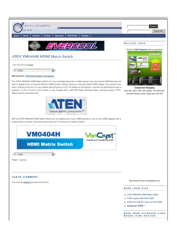
Installation GuideAT-OPUS-68MOpus 4K HDR HDMI to HDBaseT 6x8 Matrix SwitcherAT-OPUS-68MThe Atlona AT-OPUS-68M is part of the Opus Series of HDMI to HDBaseT matrix switchers for high dynamic range (HDR) formats. The 6x8 matrix switcher is HDCP 2.2 compliant andsupport 4K/UHD video @ 60 Hz with 4:4:4 chroma sampling, as well as HDMI data rates up to 18Gbps. The Opus Series enables flexible routing to HDBaseT outputs plus two additional HDMIoutputs, and is compatible with the Atlona AT-OPUS-RX receiver or AT-JUNO-451-HDBT switcher for transmission of HDMI, Ethernet pass-through, and bidirectional IR and RS-232 controlsignals up to 330 feet (100 meters) over CAT6a/7 cable. Visually lossless VESA Display StreamCompression (DSC) enables HDR and 4K/60 4:4:4 signal extension over HDBaseT with little tono latency. Opus matrix switchers are equipped with a comprehensive host of audio and controlsystem integration features, making them ideal for a wide range of residential and commercialapplications requiring multi-zone AV distribution.Package Contents1 x AT-OPUS-68M1 x Captive screw connector, 5-pin7 x Captive screw connector, 4-pin10 x Captive screw connector, 3-pin1 x Pair rack mount ears4 x Feet w/screws1 x IEC power cord1 x IR remote control1 x Installation GuideIMPORTANT: Visit https://atlona.com/product/AT-OPUS-68M for the latest firmwareupdates and User Manual.1
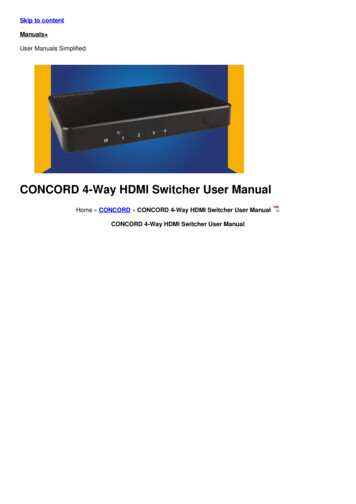
Installation GuideAT-OPUS-68MPanel ELEDIDINFOOPUS TM345AT-OPUS-68MAT-OPUS-810MHDMI IN12HDBaseT OUT435611LANDEBUGRX TXRS-232SIR INLL2TOSLINK IN612331728345TOSLINK OUT9 106AUDIO IN75PoEPoEPoELINKLINKLINK12RL83RL32SS4RLAUDIO OUT654SS5LRSSIR IN11Function ButtonsPower - Sets the unit in and out ofstandby.Enter - Used for making selections.FNC - Use to switch number buttons totheir secondary function.CANCEL - Navigates back one step in theOSD.L7R1LSL4SCHASSISGROUND8R32S8765SONRSS8SSIR OUT12138DEBUGConnect a mini USB cable from this portto a PC to troubleshoot the unit.9Control PortConnect a third party controller or PCto control the matrix through either IR orRS-23210Number ButtonsUse for selection of inputs and outputs.1 - Press FNC 1 to route selected input11to all outputs.2 - Press FNC 2 to turn the front IRreceiver on and off.3 - Press FNC 5 to open the EDID menu. 124 - Press FNC 6 to display the devicefirmware. Press 6 again to view more info.HDMI INConnect HDMI cables to these ports fromHDMI sources.6R76PoELINK114PoELINKLR3PoELINK2R2HDMI OUT141516TOSLINK OUTThese ports provide digital audio output toaudio DSPs, amplifiers, or player devices.AUDIO INConnect unbalanced 2CH audio sourcesto these ports.IR INConnect a control system to these portsto route IR signals to the correspondingHDBaseT outputs.13AUDIO OUTThis port provides source audio 2CH deembedding and direct audio loop throughfor the audio inputs.14IR OUTThese ports provide an output for IRsignals to each source and the two localHDMI outputs.4HDBaseT OUTConnect a CAT5e/6/6a/7 cable from thisport to an HDBaseT receiver.5HDMI OUTConnect HDMI cables from these ports tolocal HDMI displays.6TOSLINK INConnect digital audio sources to theseports.15Power SwitchToggle this switch to power the unit onor off.7LANConnect an Ethernet cable from this portto a Local Area Network (LAN).16100-240VAC 50/60Hz Power PortConnect the included IEC cord from thisport to the wall for power.2
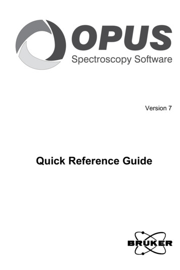
Installation GuideAT-OPUS-68MControlA 5-pin captive screw connector for control has been included. The first three terminals are RS232 control, the last two terminals are for IR.RS-232RX TX GNDIRGND RX TXPin out will be determined by theRS-232 cable and connect asRX (receive), TX (transmit) and(Ground).GND SIR IN is connected by a ground andsignal wire. Use with 3rd party controlsystems. For easy termination, Atlonarecommends using the 2 meter IRcable AT-LC-CS-IR-2M.IR4-pin captive screw connectors have beenincluded for IR routing. Each 4-pin connectwill provide connection for 2 IR ports. All IRports will use a Ground ( ) and signal (S)wire.1 2SSAudioLConnect to an audio DSP, amplifier, or otheraudio distribution or player devices. Onlyunbalanced 2CH connections are compatiblewith the 3-pin captive screw audio ports.R Positive RGround Positive LUnbalancedMounting InstructionsThe AT-OPUS-68M can be mounted in a standard 19-inch rack or placed freestanding on top ofa desk or table.Rack installation1.Remove the front two case screws from the sides of the case.2.Attach the included rack ears to each side of the AT-OPUS-68M using the case screws.3
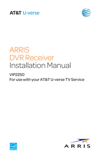
Installation oERMIHDINRL24SS5SSSSS TIR OU8MPUS-6AT-OSSS65SS4R3L5R32AU87LRONR1098764RLTR DIO IN4876PoEPoEPoEPoE72ISASSCH NDOUGRPoESS21SS4IR IN3S1SR310MPUS-8AT-OLR2LDIOAU210IN1981STXRX 232IR INRS-GDEBU456TK 2 SLINKTO1USTMOPUSTMOP3.Install the Opus matrix into a rack, using four rack screws.NOTE: Increase the air flow as needed tomaintain the recommended temperature insidethe rack.NOTE: Do not exceed the maximum weightloads for the rack. Install heaver equipment inthe lower part of the rack for ROUNDONR10SSSSSSSIR K8PoEPoEPoEPoEPoEPoEPoEHDBaseT432187SS21SS4IR IR CEL1FNC42TOSLINKIN31TMOPUSSurface mountingThe AT-OPUS-68M can be placed freestanding on top of a desk, a table, or in a cabinet. Toprevent damage to the surfaces or unnecessary movement of the matrix, four feet have beenincluded.1.Turn the unit upside down.2.Install each foot using the included feet screws, the rubber grips of the feet should be facingup during installation.3.Turn the unit right-side up and place it in the desired location.4
Installation GuideAT-OPUS-68MOPUS1TM2 INKSLINTO3FNC1ELNCCA2LAN5TK OU4SLINTOGDEBU-H2H-44MRENTERS-TXRX 232EDIDOINF6IR 2S1R2LKLINPoE5S TIR T-OSL41103S1R6IR INSL592SSIN81IN788TOU4KLINON5PoE6ISASSCH NDOUGR7MIHDTOU8Installation1.Connect up to 6 HDMI sources to the HDMI IN ports.2.Connect up to 6 HDBaseT receivers (AT-OPUS-RX or AT-JUNO-451-HDBT) to the HDBaseTOUT ports.3.Connect up to 2 local HDMI displays to the HDMI OUT ports.4.Connect up to 3 digital audio sources to the TOSLINK IN ports.5.Connect up to 2 unbalanced analog audio inputs to the AUDIO IN ports.6.Connect the TOSLINK OUT ports to an audio distribution device.7.Connect the 2CH analog AUDIO OUT ports to a DSP, or audio amplifier.8.*Optional* For control, connect to the captive screw port for IR and RS-232.9.*Optional* For IP control and/or Ethernet routing, connect a network switch to the LAN port.10. *Optional* For IR routing to and from sources and zones, connect a control system, IRreceivers, or IR emitters to the IR IN and IR OUT ports.11. Connect the included IEC power cord to the 100-240VAC 50/60Hz power port.12. Connect the power cord to an AC outlet.5
Installation GuideAT-OPUS-68MWebGUIThe OPUS matrix includes a built-in webGUI, which allows easy management and control of allfeatures. Follow the instructions below to access the webGUI.1.View the IP address of the unit using the front panel OSD. Press the FNC button. Press button 6 (INFO). The firmware version will display on the front panel screen. Press button 6 again to bring up the IP address.NOTE: If the unit is not receiving an IP address from a DHCP server, the unit will defaultto 192.168.0.150 255.255.255.0. To set the unit to a set static IP, press the FNC buttonfollowed by 4. Select the Static IP option and press enter. The default static IP addressand netmask is 192.168.1.254 255.255.0.0.2.Launch a web browser and enter the IP address of the unit.3.The OPUS Login page will be displayed.4.Enter the following information on the Login page.Login:Password:5.adminAtlonaClick the Login button.AMS 2.0For full configuration of the OPUS, AMS 2.0 is available from https://atlona.com/AMS for free.Two options can be used for installation: The free Linux based software download or the easy toinstall server hardware (AT-AMS-HW).Once AMS has been set up:1.Open a browser on the same network as AMS 2.0 and go to the IP of AMS 2.0.a.View the AMS 2.0 installation instructions on how to find the IP of the software.2.Enter the login information on the AMS 2.0 page, then click the Login button.3.View the OPUS manual for routing and configuration.6
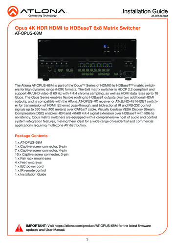
Installation GuideAT-OPUS-68MConnection DiagramAT-VGW-250WAYGATE44diame422Media PlayerO tBOXControl SystemAuCable BoxdioAudio/V/VideotrneeEthideoAV 4BluRay PUSAT-OSeTHDBasSSHDMI4IR IN810MPUSAT-OCH7CH62LAUDIOSRXTX9DEBUGIR IN7INoLINKOUTIVERRECEPWRNETETHERIR OUTLINKRS-232INAUDIO56K 2TOSLINKSTXUS-RXAT-OP67IR 13CH8idePoESS/VSSSIR otSTMOPUlifernel l Amphan iona4-CfessProI0Audio FWINPUTERPOWDISPLAY4INPUT 321JUNOXTMeolnsmeCoGasolee ConGamGame ConsoleGame ConsoleDISPLAYTroubleshootingProblemSolutionI am not receivingmultichannel audio or 3Dvideo. By default, multichannel audio and 3D will not passunless all devices support those features. Set each port’sEDID through the front panel, webGUI, or RS-232.What firmware am I on? To view the device firmware version, press the FNCbutton, followed by button 6 (INFO). The firmware willappear on the front panel OSD.What’s my baud rate? To view the baud rate of the RS-232 port, press the FNCbutton, followed by button 6, then press button 2. Thebaud rate will appear on the front panel OSD.What’s my IP? To view the IP address of the unit, press the FNC button,followed by the 6 button twice. If the unit is connected to a non-DHCP network, pressFNC, followed by the 4 button. Select the Static IPoption and press Enter. The default static IP address andnetmask is 192.168.1.254 255.255.0.0.7
Installation GuideAT-OPUS-68MVersion 1atlona.com 408.962.0515 877.536.3976 2018 Atlona Inc. All rights reserved. “Atlona” and the Atlona logo are registered trademarks of Atlona Inc. All other brand names and trademarks or registeredtrademarks are the property of their respective owners. Pricing, specifications and availability subject to change without notice. Actual products, product images, andonline product images may vary from images shown here.8
2. Enter the login information on the AMS 2.0 page, then click the Login button. 3. View the OPUS manual for routing and configuration. WebGUI The OPUS matrix includes a built-in webGUI, which allows easy management and control of all features. Follow the instructions below to access the webGUI. 1. View the IP address of the unit using the .