Transcription
Communication Settings:Allen Bradley(Control Logix PLC )andIDEC Touchscreens(5.7” HG2G, 10.4” HG3F, AND 12.1” HG4F)Via Ethernet/IP
Introduction:The following information will help you configure the IDEC touchscreens (5.7” HG2G,10.4” HG3F, or 12.1” HG4F) and the Allen Bradley Control Logix PLC using the ABEthernet IP driver. For other supported Allen Bradley PLCs and their communicationsettings/range of addresses, please refer to the WindO/I-NV2 manual (select “HostInterface” then Connection to a /WindOI/V330/Manual/mainmenue.pdfEthernet/IP Settings (Control Logix)Required Cables:Ethernet Cables (one for PLC and one for HMI)1756-CP3 (Control Logix programming cable)HG9Z-XCM1A (TouchScreen programming cable)Required Software:Install WindO/I-NV2 Version 3.30 (programming software for HG3F/4F)Install Allen Bradley RSLinx and RSLogix5000 (programming software forControlLogix)Devices used for testing:1. AB ControlLogix PLC2. 1756-ENET (Interface Module used with ControlLogix)3. IDEC TouchScreeen HG4F-JT22TFW
Below are the IP addresses used for testing: (The IP address may differdepending on the environment)1.2.3.192.168.104.32 (assigned in the TouchScreen)192.168.104.33 (assigned in the ControlLogix/Interface Module)Subnet Mask: 255.255.255.0 (used on Touchscreen & Interface Module)Default Gateway: 192.168.104.254 (used on Touchscreen & Interface Module)Step 1: RSLinx and RSLOGIX SOFTWAREConfigure the AB ControlLogix PLC1) Connect the programming cable (part number: 1756-CP3) from the PC to theControlLogix programming port.1756-CP32) Launch the RSLinx software. The RSLinx allows you to configure the AB driver.Select the Communications Configure Drivers.3) Configure Drivers:a) Select “RS232 DF1 Devices”b) Click the Add New buttonc) Choose a name for the driver and then click OKd) Click Configure to configure the device.
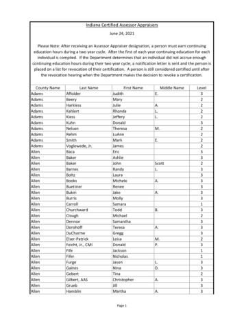
4)Next, make sure to follow the settings below, except the Communication Port(select your own communication port), and click on the Auto-Configure button.5. Once the settings are done, Click the OK button and it should show you that the driveris in the Running status.6. Click Close
The picture below shows that you have successfully configured the PC to talk to theControlLogix PLC.Step 2: Configure the AB ControlLogix and Interface Unit usingRSLogix5000 software1)i) Launch RSLogix5000 and select File New.ii) Select the Processor Type from drop drown menu.iii) Enter the program name then click OK.
2) Select Communication Who ActiveClick Download
3) Click on the Rem Prog drop down menu and select Go Offline.4) Right mouse click on I/O Configuration to select New Module, and then select theModule Type as shown below and click OK.
5) Type name on Module Properties box, enter the IP address, and then click Finish.6) As shown below, the newly selected Module Type appears in the I/O Configurationfolder.Right mouse click on the Module Type and then select Properties.
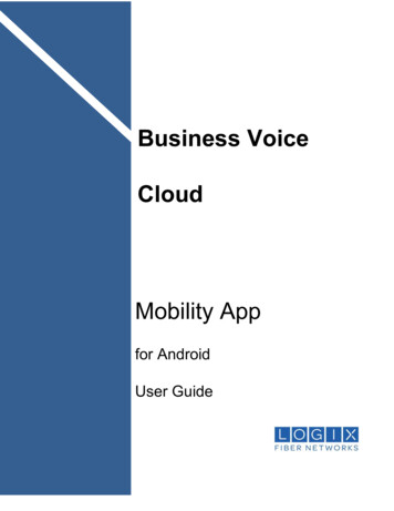
7) Under the General tab, enter the valid IP address. Then go to the Port Configurationtab in ONLINE mode and uncheck the "Enable DHCP (DHCP must be configured toreturn a fixed address.) Enter the valid IP address, Subnet Mask and Gateway Address forthe controller and click on Set then OK.
Creating Tags and Assigning the Map8) Double click on the Controller Tags on left panel.9) Enter below Tag Name and data type in Edit Tag.The IDEC MICRO/I support INT, SINT, DINT and REAL.10)MappingTo map the PLC/SLC messages, make sure the program is in OFF Linea) Select Logic in Main Menub) Click the Map PLC/SLC Messagesc) Name the File Number and the Tag Name as shown below.
d) Click OK11) Download the program to the controller.Step 3: WINDO/I NV2 SOFTWAREConfigure the HG3F/HG4F by creating a program in the WindO/I NV2 software.HG9Z-XCM1AEthernet CableEthernet Cable1) Connect the programming cable (part number: HG9Z-XCM1A) from the PC to theHG3F/HG4F (via serial 2 port).2) Launch WindO/I NV2 version 3.3Create a File name then click Next to continue.
3) Select the O/I and Model type. Click Next to continue.4) Select the Host I/F Driver: Allen Bradley, Ethernet/IPClick Next to continue.5) In the Project Settings window, select the Communication Interface tab.Set the IP Address as shown:
6) Select Host I/F Network tab. Enter the Controllogix IP Address (as shown).The Station# is set to “0” (according to Controllogix device#). Leave the Port No.as is. The product is Controllogix (as used in this example).Please see the example table below for the “Device Name” and “Data type of tags inControlLogix.”Tag namesin Control LogixTag 1Wind O/I- NV2Device NameIntegerDeviceSymbolNFileNumber1Address Range0 - 999999Data type of tagsin Control LogixINTTag 2SINTSINT20 - 9999991SINTTag 3Float/REALF30 - 9999991REALTag 4Long/DINTL40 - 999999DINT
6. To test the communication between two devices over the Ethernet network, first selectNumerical Input on the Base Screen for File number 1 or Tag 1. Double click on the"Numerical Input".1) Select Numerical Input & drop on the basescreen.2) Double click Numerical Input to configure theProperties.Click this button to openDevice Browser.7. In the Device Browser window, select N: Integer, Address: 1:0, Station No.: 0 (ControlLogix is assigned as file number 1, element 0) then click the Select button to use thedevice.
Click this button to open theaddress settings window8. Download the entire project by selecting Online Download (in WindO/I-NV2, Ver.3.30) and enter 12345 in the Numerical Input as shown below.
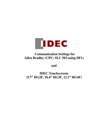
9. You should see the data 12345 will display in Controller Tag. Make sure you are inOnline Mode and Monitor Tags.
10.4" HG3F, or 12.1" HG4F) and the Allen Bradley Control Logix PLC using the AB Ethernet IP driver. For other supported Allen Bradley PLCs and their communication settings/range of addresses, please refer to the WindO/I-NV2 manual (select "Host Interface" then Connection to a PLC).


![INDEX [gfgenealogy ]](/img/44/index-to-wills-cascade-county.jpg)