Transcription
MAINTAIN YOUR VWR REFRIGERATOR TORECEIVE THE MOST EFFICIENT AND SUCCESSFUL OPERATION!TABLE OF CONTENTSSAFETY INFORMATIONSafety Precautions1Proper Disposal, Connecting Electricity, & Adapter Plugs2INSTALLATIONOwnership & Uncrating3Wire Gauge Chart & Electrical Installation3Locating and Leveling5Installation of Legs or Castors6Sealing Cabinet to the Floor8SETUPStandard Accessories9Cabinet Adjustment11OPERATIONStartup13Mechanical Temperature Controls Sequence of Operation13Electronic Temperature Controls Sequence of Operation19MAINTENANCE, CARE, CLEANINGCleaning Condenser Coil29Important Warranty Information30Stainless Steel Equipment Care and Cleaning31General Maintenance32WARRANTYWarranty330516INSTALLATION MANUALVWR CHROMATOGRAPHY REFRIGERATOR: GDM MODEL50 SB WP-432
NOTICE TO CUSTOMER:LOSS OR SPOILAGE OF PRODUCTS IN YOUR REFRIGERATOR ISNOT COVERED BY WARRANTY. IN ADDITION TO FOLLOWINGRECOMMENDED INSTALLATION PROCEDURES YOU MUST RUNTHE REFRIGERATOR 24 HOURS PRIOR TO USAGE.SAFETY INFORMATIONHow to Maintain Your Cooler to Receive the Most Efficient andSuccessful Operation.You have selected one of the finest commercial refrigeration unitsmade. It is manufactured under strict quality controls with only thebest quality materials available. Your TRUE cooler when properlymaintained will give you many years of trouble-free service.WARNING: Use this appliance for its intended purpose asdescribed in this Owner Manual.TO LOCATE REFRIGERANT TYPE, SEE SERIAL LABELINSIDE CABINET. This cabinet may contain fluorinated greenhouse gas covered by the Kyoto Protocol (please refer to cabinet’sinner label for type and volume, GWP of 134a 1,300. R404a 3,800).FOR HYDROCARBON REFRIGERATION ONLY (R-290)SEE BELOW: DANGER - Risk of fire or explosion. Flammable refrigerantused. Do not use mechanical devices to defrost refrigerator. Donot puncture refrigerant tubing.DANGER - Risk of fire or explosion. Flammable refrigerantused. To be repaired only by trained service personnel. Do notpuncture refrigerant tubing. CAUTION - Risk of fire or explosion. Flammable refrigerantused. Consult repair manual/owner’s guide before attemptingto service this product. All safety precautions must be followed. CAUTION - Risk of fire or explosion. Dispose of properlyin accordance with federal or local regulations. Flammablerefrigerant used. CAUTION - Risk of fire or explosion due to punctureof refrigerant tubing; follow handling instructions carefully.Flammable refrigerant used. CAUTION - Keep clear of obstruction all ventilation openingsin the appliance enclosure or in the structure for building-in.1SAFETY PRECAUTIONSWhen using electrical appliances, basic safety precautions should befollowed, including the following: This refrigerator must be properly installed and located inaccordance with the Installation Instructions before it is used. Do not allow children to climb, stand or hang on the shelvesin the refrigerator. They could damage the refrigerator andseriously injure themselves. Do not touch the cold surfaces in the freezer compartmentwhen hands are damp or wet. Skin may stick to theseextremely cold surfaces. Do not store or use gasoline or other flammable vapors andliquids in the vicinity of this or any other appliance. Do not storeexplosive substances such as aerosol cans with a flammablepropellant in this appliance. Keep fingers out of the “pinch point” areas; clearances betweenthe doors and between the doors and cabinet are necessarilysmall; be careful closing doors when children are in the area.Unplug the refrigerator before cleaning and making repairs. Setting temperature controls to the 0 position does notremove power to the light circuit, perimeter heaters, orevaporator fans.NOTE: We strongly recommend that any servicing be preformedby a qualified technician.
DANGER!RISK OF CHILDENTRAPMENTPROPER DISPOSAL OF THE REFRIGERATORChild entrapment and suffocation are not problems of the past.Junked or abandoned refrigerators are still dangerous even if theywill sit for “just a few days.” If you are getting rid of your old refrigerator, please follow the instructions below to help prevent accidents.BEFORE YOU THROW AWAY YOUR OLDREFRIGERATOR OR FREEZER: Take off the doors. Leave the shelves in place so that children may not easily climbinside.APPLIANCE DISPOSALWhen recycling appliance please make sure that the refrigerants arehandled according to local and national codes, requirements andregulations.REFRIGERANT DISPOSALYour old refrigerator may have a cooling system that uses “OzoneDepleting” chemicals. If you are throwing away your old refrigerator,make sure the refrigerant is removed for proper disposal by a qualified service technician. If you intentionally release any refrigerants youcan be subject to fines and imprisonment under provisions of theenvironmental regulations.USE OF EXTENSION CORDSWARNING!HOW TO CONNECT ELECTRICITYDO NOT, UNDER ANY CIRCUMSTANCES, CUT ORREMOVE THE GROUND PRONG FROM THE POWERCORD. FOR PERSONAL SAFETY, THIS APPLIANCEMUST BE PROPERLY GROUNDED.The power cord from this appliance is equipped with a groundingplug which minimizes the possibility of electric shock hazard.Have the wall outlet and circuit checked by a qualified electrician tomake sure the outlet is properly grounded.If the outlet is a standard 2-prong outlet, it is your personal responsibility and obligation to have it replaced with the properly groundedwall outlet.The refrigerator should always be plugged into it’s own individualelectrical circuit, which has a voltage rating that matches the ratingplate.This provides the best performance and also prevents overloadingbuilding wiring circuits which could cause a fire hazard from overheated wires.Never unplug your refrigerator by pulling on the power cord. Alwaysgrip plug firmly and pull straight out from the outlet.Repair or replace immediately all power cords that have becomefrayed or otherwise damaged. Do not use a cord that shows cracksor abrasion damage along its length or at either end.When removing the refrigerator away from the wall, be careful notto roll over or damage the power cord.If supply power cord is damaged it should be replaced with originalequipment manufacture parts. To avoid hazard this should be doneby a qualified service technician.NEVER USE AN EXTENSION CORD! TRUE will not warranty any refrigerator that has been connected to an extension cord.USE OF ADAPTER PLUGSREPLACEMENT PARTSNEVER USE AN ADAPTER PLUG! Because of potential safetyhazards under certain conditions, we strongly recommend against theuse of an adapter plug. Component parts shall be replaced with like components. Servicing shall be done by authorized service personnel, tominimize the risk of possible ignition due to incorrect parts orimproper service. Lamps must be replaced by identical lamps only.NORTH AMERICA USE ONLY! If the supply cord is damaged, it must be replaced by a specialcord or assembly available from the manufacturer or its serviceagent.NEMA plugsThe incoming power source to the cabinet including any adaptersused must have the adequate power available and must be properlygrounded. Only adapters listed with UL should be used.TRUE uses these types of plugs. If you do not have the right outlethave a certified electrician install the correct power source.NOTE: International plug configurations vary by voltage and 115/60/1NEMA-5-20R208-230/60/1NEMA-6-15R2
INSTALLATIONOWNERSHIPTo ensure that your unit works properly from the first day, it mustbe installed properly. We highly recommend a trained refrigerationmechanic and electrician install your equipment. The cost of a professional installation is money well spent.Before you start to install your unit, carefully inspect it for freightdamage. If damage is discovered, immediately file a claim with thedelivery freight carrier.123456is not responsible for damage incurred during shipment.UNCRATINGTOOLS REQUIRED Adjustable Wrench Phillips Screwdriver LevelThe following procedure is recommended for uncrating the unit:A. Remove the outer packaging, (cardboard and bubbles orstyrofoam corners and clear plastic). Inspect for concealeddamage. Again, immediately file a claim with the freight carrierif there is damage.B.Move your unit as close to the final location as possible beforeremoving the wooden skid.C. Remove door bracket on swinging glass door models (seeimage 1-2). Do not throw the bracket or blocks away. Forfuture cabinet movement the bracket and blocks will need tobe installed so the glass door does not receive any damage.(See image for bracket and shipping block removal)NOTE: KEYS FOR COOLERS WITH DOOR LOCKS ARELOCATED IN WARRANTY PACKETS.3
ELECTRIC INSTALLATION & SAFETY INFORMATION If the supply cord is damaged, it must be replaced by a specialcord or assembly available from the manufacturer or its serviceagent. Lamps must be replaced by identical lamps only. Appliance tested according to the climate classes 5 and 7temperature and relative humidity.NOTE: Refrigerators with the factory installed Grounded ElectricalDuplex with Cover will have two (2) power cords. The power cordlocated on the back or side walls is for Duplex. The power cordlocated in the lower back is for the refrigerator. Both power cordswill require their own separate dedicated circuit.ELECTRICAL INSTRUCTIONSA. Before your new unit is connected to a power supply, check theincoming voltage with a voltmeter. If anything less than 100% ofthe rated voltage for operation is noted, correct immediately.B. All units are equipped with a service cord, and must bepowered at proper operating voltage at all times. Refer tocabinet data plate for this voltage.Duplex power cordRECOMMENDS THAT A SOLE USE CIRCUIT BEDEDICATED FOR THE UNIT.Main power cordWARNING: Compressor warranties are void if compressor burnsout due to low voltage.WARNING: Power supply cord ground should not be removed!WARNING: Do not use electrical appliances inside the food storage compartments of the appliances unless they are of the typerecommended by the manufacturer.NOTE: To reference wiring diagram, remove front louvered grill, wiring diagram is positioned on the inside cabinet wall.WIRE GAUGE CHART115 VoltsAmps23456Distance In Feet To Center of Load20 30 40 50 60 70 80 90 100 120 140 888668666666665665546554465443544334433243221230 VoltsAmps56789Distance In Feet To Center of Load20 30 40 50 60 70 80 90 100 120 140 22114
LOCATINGLEVELINGA. Remove louver from the front of cabinet (see page 19 forlouver grill removal / reinstallation) and backguard (if applicable)from rear of cabinet.A. Set unit in its final location. Be sure there is adequate ventilationin your room. Under extreme heat conditions, (100 F ,38 C ), you may want to install an exhaust fan.B.Skid bolts are located in each of 4 corners inside cabinetbottom. See photo A.C. Remove skid bolts. See photo B.WARNING: WARRANTY IS VOID IF VENTILATION ISINSUFFICIENT.D. Cut straps if applicable. See photo C.E.Carefully lift cabinet off of skid.F.Appliance tested according to the climate classes 5 and 7 fortemperature and relative humidity.B.Proper leveling of your cooler is critical to operating success(for non-mobile models). Effective condensate removal anddoor operation will be effected by leveling.C. The cooler should be leveled front to back and side to side witha level.D. Ensure that the drain hose or hoses are positioned in the pan.ARemoving skid frombottom of cabinet.E.Free plug and cord from inside the lower rear of the cooler(do not plug in).F.The unit should be placed close enough to the electrical supplyso that extension cords are never used.WARNING: CABINET WARRANTIES ARE VOID IFOEM POWER CORD IS TAMPERED WITH. WILL NOTWARRANTY ANY UNITS THAT ARE CONNECTED TOAN EXTENSION CORD.PCNOTEWhen moving cabinet DO NOT pushon door hinges.51227-5REMOVE COVER MAKE POWER CONNECTIONNEPCO/CENTRALABB
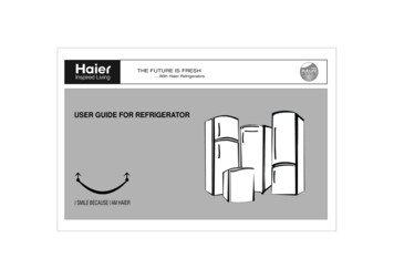
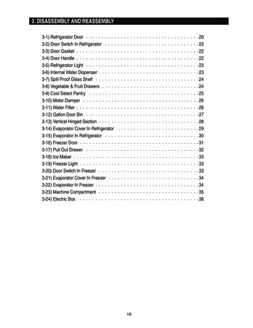
INSTALLATION OF CASTORS OROPTIONAL LEGSImportant Safeguard for installation of leg/castor. Images 1-5 demonstrate procedure.SECURING CASTORS AND LEGSTo obtain maximum strength and stability of the unit, it is importantthat you make sure each castor is secure. Optional legs are handtightened securely against the lower rail assembly see image 4-5. Thebearing race on the castor or the top edge of the leg must make firmcontact with the rail.12Thread castor into the underside ofcabinet frame rail.For leveling, insert the shim betweencastor and frame rail.LEVELING SHIMSFour leveling shims have been provided for leveling castored unitspositioned on uneven floors. Shims must be positioned between railend and bearing race.A. Turn the bearing race counter-clockwise until the cabinet islevel. Level front to back and side to side. (diagonally)B.Install the desired number of shims, making sure the slot of theshim is in contact with the threaded stem of the castor. Seeimage 2.C. If more than one shim is used, turn the slot at a 90 angle sothey are not in line.34Use the tool provided to tighten thecastor into place.Thread leg into cabinet bottomframe rail.D. Turn the bearing race clockwise to tighten and secure thecastor by tightening the anchoring bolt with a 3/4 inch openend wrench or the tool provided. See image 3.CAUTION: TO AVOID DAMAGE TO LOWER RAILASSEMBLY, SLOWLY RAISE UNIT TO UPRIGHTPOSITION.NOTE: OPEN HOLES LOCATED ON THE CROSSMEMBERS OF THE FRAME RAIL SHOULD BEPLUGGED BEFORE UNIT IS IN USE.5The end of the leg is adjustable foreasy leveling.Lower RailAssemblyLower Rail AssemblyRail EndSnug FitHereRail EndBearingRaceSnug FitHereLeveling ShimLegCastor6
SEALING CABINET TO FLOORSTEP 1 - Position Cabinet - Allow one inch between the wall andrear of the GDM refrigerator to assure proper ventilation. For GDMfreezers 3 inches between the wall and rear of the cabinet will assureproper ventilation.STEP 2 - Level Cabinet - Cabinet should be level, side to side andfront to back. Place a carpenter’s level in the interior floor in fourplaces:A. Position level in the inside floor of the unit near the doors.(Level should be parallel to cabinet front). Level cabinet.B.Position level at the inside rear of cabinet. (Again level shouldbe placed parallel to cabinet back).C. Perform similar procedures to steps A & B by placing the levelon inside floor (left and right sides - parallel to the depth of thecooler). Level cabinet.STEP 6 - Raise and block the rear of the cabinetSTEP 7 - Apply sealant on floor as outlined in Step 5 on otherthree sides.STEP 8 - Examine to see that cabinet is sealed to floor aroundentire perimeter.NOTE: Asphalt floors are very susceptible to chemical attack. Alayer of tape on the floor prior to applying the sealant will protectthe floor.NSF APPROVED SEALANTS:1. Minnesota Mining #ECU800 Caulk2. Minnesota Mining #ECU2185 Caulk3. Minnesota Mining #ECU1055 BeadSTEP 3 - Draw an outline on the base on the floor.4. Minnesota Mining #ECU1202 BeadSTEP 4 - Raise and block the front side of the cabinet.5. Armstrong Cork - Rubber CaulkSTEP 5 - Apply a bead of “NSF Approved Sealant”, (see list below),to floor on half inch inside the outline drawn. The bead must be heavyenough to seal the entire cabinet surface when it is down on thesealant.6. Products Research Co. #5000 Rubber Caulk77. G.E. Silicone Sealer8. Dow Corning Silicone Sealer
SETUPSTANDARD ACCESSORIESSHELF INSTALLATION:SHELVING INSTALLATION / OPERATIONFor Proper Shelf Clip Installation Please Read The FollowingInstructions.SHELF INSTALLATION:STEP 1A. Hook shelf clips onto shelf standards.B.Position all four shelf clips equal in distance from the floor forflat shelves.C. Lower front of gravity feed Trac organizers to enable properfeed.D. Place shelves on shelf clips making sure all corners are seatedproperly.WIRE SHELVES: Wire shelves are oriented so that cross supportbars are facing down.Install the top tab of the shelf clip into the proper hole. Push up onthe bottom of the clip. See image 1.STEP 2Bottom tab of the shelf clip will fit tightly.You may need to squeeze ortwist the bottom of the shelf clip to install. See images 2 & 3.STEP 3After installation, the shelf clip will fit snug into the shelf standard.The shelf clip should not be loose or able to wiggle out of the shelfstandard.SHELF INSTALLATION TIPSRetainerClip1.Install all the shelf clips before installing the shelves.2.Start at the bottom in terms of shelf installation and work yourway up.3.Always lay the back of each shelf down on the rear clips beforethe front.OrganizerT-Series& ing top tab of shelf clipShelfClip2Installing bottom of the shelfclipPillaster(I-beam)WARNING!Do not use pliers or any crimping tools wheninstalling shelf clips. Altering shelf clips in anyway can lead to shelving instability.3You may need to squeeze or twistthe bottom of the shelf clip toinstall4Shelf clip installation complete8
SLIDE DOOR OPERATION (CABINET ADJUSTMENT)STEP 1 - Before removing slide door do not use the side latch.Tension on the door cord is needed to execute these operationinstructions. Doors can not be removed unless placed in specific locations stated in these instructions.STEP 3 - After centering the door lift it up and tilt top of door towardsthe back of the unit so the rollers are out of the top channel. Swingthe bottom of the door out of the bottom channel. Then remove thedoor and set it down. See image 4.STEP 2Two Door Units: Slide the front door so it is centered on thecabinet. The door can not be removed unless it is centered. Seeimage 1 for door channel openings and image 2 for centeringdoor.41(Two Door Units ONLY)(TWO DOOR UNITS SKIP TO STEP 6)CENTERED DOORSTEP 4 - Slide right door to the left so left edge lines up with theleft edge of Logo located above the door. See image 5. Then lift doorout of track same way as image 4.Logo2(Two Door Units ONLY)Three Door Units: Slide the middle door to the right so it iscentered with the left edge of the right door. See image 3.5(Three Door Units ONLY)39(Three Door Units ONLY)
STEP 5 - Slide left door to the right so right edge lines up with theend of the Logo located at the top of the door frame. See image 6.Then lift door out of track same way as image 4.LogoTO ADJUST SLIDE DOORSTEP 1 - After cabinet is installed in a final location and correctly leveled check for any openings when the slide doors are completely closed.If there are any gaps/openings between the closed doors and cabinet,the doors will need to be adjusted.STEP 2 - Using a 7/16" wrench or adjustable wrench and 1/8" Allenwrench loosen roller and move along slotted hole. After adjustmenthas been made tighten the roller into place. See image 10.6(Three Door Units ONLY)10NOTE: Door cord will either be nylon cord or metal cable.SLIDE DOOR UNITS WITH HOLD OPEN FEATURESTEP 6 - Remove door cord from roller bracket. The black plastictab holding the door cord slides out the back. See images 7 & 8.These instructions explain how to keep door in open position.A. Slide the door open.B.Latch the door in the open position from the back side of door(notch in track).C. Door latch in image 1 is in the open position.D. Door latch in image 2 is in the closed position.78Door roller bracket with metal cable. Door roller bracket with nylon cord.STEP 7 - Let the door cord slowly retract back into the door sidechannel.12Rear view of door & trackSTEP 8 - When reinstalling door, make sure door cord grommetattaches to roller slot closest to pulley. See image 9.9Door closing to the left10
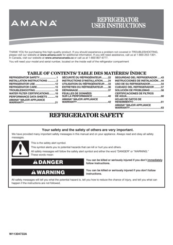
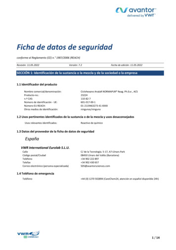
CHROMATOGRAPHY ACCESSORIES1. Electronic Control (factory installed only) Digital programmable temperature control allows temperaturechanges in small increments.2. Grounded Electrical Duplex with Cover (factory installed only) Used to provide power for stirring devices or other testingequipment inside cooler Duplex is included with separate power cord that will requireits own dedicated circuit. May be mounted on the back, left or right inner wall ofthe cooler12343. Access Port (factory installed only) Used to allow access to run lines, cords, or to move productinside cooler. May be mounted on the back, left or right inner wall ofthe cooler4. Chromatography Mast (factory or field installed) Vertical pole mounted inside to clamp and hold beakers orother equipment.5. Probe Port (factory installed only) Used to allow access to run temperature probes inside cooler. Located on the outside back wall near the top.5OUTSIDE6. Qualifying Probe Port (factory installed only) Used to allow access to run a probe in the evaporator areawhen qualifying the cooler. Located on the inside top cover.INSIDE6OPERATIONSTARTUPA. The compressor is ready to operate. Plug in the cooler.B.Temperature controls are factory-set to give refrigerators anapproximate temperature of 2-8 C (35.6-46.4 F). Allow unitto function several hours, completely cooling cabinet beforechanging the control setting.Temperature Control Location and Settings. T emperature control type will vary upon model and age ofcabinet. M echanical control or electronic control without display:- Inside cabinet- Behind cabinet- Behind front or rear access grill E lectronic control with display:- In countertop- In top louvered panel- In or behind bottom louvered grillSee website for adjustments, sequence of operation, and moreinformation.11C. Excessive tampering with the control could lead to servicedifficulties. Should it ever become necessary to replacetemperature control, be sure it is ordered from your dealer orrecommended service agent.D. Good air flow in your unit is critical. Be careful to load productso that it neither presses against the back wall, nor comeswithin four inches of the evaporator housing. Refrigerated airoff the coil must circulate down the back wall.NOTE: If the unit is disconnected or shut off, wait five minutesbefore starting again.RECOMMENDATION - Before loading product we recommendyou run your unit empty for two to three days. This allows you tobe sure electrical wiring and installation are correct and no shippingdamage has occurred. Remember, our factory warranty does notcover product loss!LIGHT SWITCH LOCATION: Light switch location dependsupon the GDM model. Most GDM models will have the light switchlocated on the right side of the ceiling inside the unit. Most instancesthe switch is located next to the temperature control.
MECHANICAL TEMPERATURE CONTROLSCOIL SENSINGAn evaporator coil sensing temperature control ensures that the evaporator coil will remain clearof frost and ice by not allowing the compressor to restart until the coil temperature is above thefreezing temperature. This is considered an off cycle defrost.MECHANICAL TEMPERATURE CONTROL GENERAL SEQUENCE OF OPERATIONMECHANICAL CONTROL REFRIGERATOR GENERAL SEQUENCE OF OPERATION1. Cabinet is plugged in.a. Interior lights will illuminate on Glass Door Models only. If lights do not come on verify the light switch is in the “ON”position. Solid door cabinets may or may not have lights that may be controlled by the door switch.2. The compressor and evaporator fans will start if the temperature control is calling for cooling. (If the compressor does notstart, verify that the temperature control is not in the “OFF” or “0” position.)3. The temperature control may cycle the compressor and evaporator fan(s) on and off together.a. The temperature control is sensing the evaporator coil temperature.b. The temperature control should be set on the #4 or #5.c. The warmest setting is #1, the coldest is #9, and #0 is the off position.d. The thermometer is designed to read and display a cabinet temperature not a product temperature.The thermometer may reflect the refrigeration cycle swings of up and down temperatures.The most accurate temperature on a cabinet's operation is to verify the product temperature.4. There is not a defrost timer as the temperature control will initiate the off-cycle defrost during each refrigeration cycle.a. At this time, the compressor will and the evaporator fan(s) may turn off. Defrost heaters are not installed on refrigeratorsand therefore will not be energized.b. After the evaporator coil temperature has been reached, as determined by the temperature control, the compressor willrestart.5. There may be a timer located on the condensing unit base. This timer is not used for a defrost event. The timer will changethe rotation of the reversing condenser fan motor.12
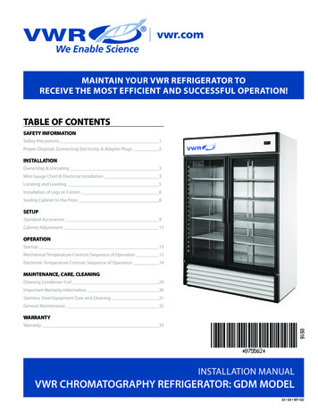
WHEN TO MAKE AN ADJUSTMENT TO A MECHANICAL TEMPERATURE CONTROLWe advise to make a mechanical temperature control adjustment only for a high altitude location.HOW TO ADJUST A MECHANICAL TEMPERATURE CONTROLOPERATION INSTRUCTIONS:Scale Guide for MeasuringREQUIRED TOOLS: Jewelers Screw Driver (Small Screw Driver)50GE CONTROL INSTRUCTIONS:510RME RWA45The scale to the right may be used as a guide for measuringdegrees of rotation required for altitude correction. See Figure 1.The arrows indicate direction of screw rotation. Turn calibrationscrew clockwise to obtain warmer operating temperatures.NOTE: Each 1/4 turn of the calibration screw is equal toapproximately 2 degrees F. Do not make more than 3/4 turn.After making adjustment, measure temperature during threecycles before adjusting again.NOTE: Only adjust the screw(small flathead) on the face ofthe control (next to the cam).See Figure 3.Follow the Altitude CorrectionTable to the right.CO40LD E R351202530Altitude CorrectionAltitude ise Turns7/6011/6015/6019/6023/6027/6030/6034/6037/60 Torx Screw (T-7)2Front of Temperature ControlCalibrationScrewTo adjust the temperature controltake the control knob off to view thecut-in screw. (See Photo Above)3Bottom of Temperature ControlCut-out AdjustmentScrew Allen (5/64" or 2 mm.)REQUIRED TOOLS:Allen Wrench (5/64")GroundTerminal15ALTITUDE CORRECTION TABLE:CALIBRATION SCREW ADJUSTSBOTH CUT-IN AND CUT-OUTINSTALLATION INSTRUCTIONSDANFOSS TEMPERATURE CONTROL ADJUSTMENTFOR HIGH ALTITUDE APPLICATIONS: CompressorTerminals6055Back of Temperature ControlCut-in AdjustmentScrew Torx (T-7)TERMS:Cut-out - Temperature sensed by the controller that shuts thecompressor off.Cut-in - Temperature sensed by the controller that turns thecompressor on.131CompressorConnectionCompressor Connection(double terminal)
INSTRUCTIONS: DANFOSS TEMPERATURE CONTROL ADJUSTMENT FORHIGH ALTITUDE APPLICATIONSSTEP 1 - Unplug cooler.STEP 2 - Remove the screws that secure the temperature control to the inset box.STEP 3 - To make these adjustments it may be necessary to remove the temperature control from the housing.NOTE: You may have to remove the wires attached to the control. Take note as to which wire is on which spade terminal.STEP 4 - Pull out gently from cabinet.NOTE: Mechanical temperature controllers are affected when functioning at high altitude.The cut-in and cut-out temperatures will be colder than when the controller functions closer to sea level.STEP 5 - For high elevation installations, it may be necessary to “warm-up” the set points. To make the adjustment, insert theappropriate tool in each adjustment screw and turn 1/4 of a revolution clockwise (to the right). This procedure will adjust boththe cut-in and cut-out about 2 F warmer.STEP 6 - Make sure to reconnect the wires to the proper spade terminal when reinstalling.INSTALLATION INSTRUCTIONSTEMPERATURE CONTROL ALTITUDE ADJUSTMENT:Scale Guide for MeasuringREQUIRED TOOLS: Allen Wrench (5/64”) Torx Screw (T-7)36090The scale to the right may be used as a guide for measuring degrees of rotation required for altitudecorrection. The arrows indicate direction of screw rotation. See Figure 1.IMPORTANT: Upright models ordered with “High Altitude” temperature controls arepre-calibrated and do not require adjustment.2701801INSTRUCTIONS: CUTLER HAMMER TEMPERATURE CONTROL ALTITUDE ADJUSTMENTSTEP 1 - Unplug cooler.STEP 2 - Turn the temperature control to the “9” position.STEP 3 - Remove the screws that secure the mounting plate to the evaporator top. See Figure 2.STEP 4 - Pull control down gently from housing.STEP 5 - Turn screws counterclockwise (CCW).STEP 6 - Reassemble to cooler housing and return the temperature control to the “5” position.14
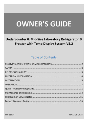
CHART612345CUTOUT7COLDER7CUTINOBUL. NO.8151922842 78 114 150 186 222 258 294 330 5OHeightCCW Adjustment(based on 360 /complete turn)
ELECTRONIC TEMPERATURE CONTROLSLAE ELECTRONIC TEMPERATURE CONTROL GENERAL SEQUENCE OF OPERATIONt1 Thermostatt2 Defrostt3 Displayt3 probe is not installed and / or activated in all applicationswhen t3 is not installed and / or activated, the display probe is t1.LAE ELECTRONIC CONTROL GENERAL SEQUENCE OF OPERATION1. Cabinet is plugged in.a. Display will illuminate.b. Interior light will illuminate on Glass Door Models only. Solid door cabinet lights are controlled by the door switch.2. After the LAE control preprogrammed time delay of up to 6 minutes, the compressor and evaporator fan(s) will start if thecontrol is calling for cooling.a. Control or condenser fans may be already pre-programmed from the factory so at the start of every compressor cycle orduring a defrost cycle, the condenser fan(s)
INSTALLATION MANUAL VWR CHROMATOGRAPHY REFRIGERATOR: GDM MODEL MAINTAIN YOUR VWR REFRIGERATOR TO . Your TRUE cooler when properly maintained will give you many years of trouble-free service. WARNING: . 5010 8 6 6 45 43 32 1 1 WIRE GAUGE CHART