Transcription
Laser markingat a glance
Laser markingat a glanceMarking lasers perform moreand more tasks in the industry.In this manual, you canfind out what role marking lasersplay in the different sectors.You will learn about the technicalbackground of processes aswell as laser systems and receivea guide to practical marking.
1A P P L I C AT I O N A R E A S A N D S E C T O R S1.1T R AC E A B I L I T Y1.2C U S T O M I Z AT I O N A N D D E S I G N1.3PROCESS PREPAR ATION AND SURFACE TREATMENT1.4M E D I C A L T EC H N O L O G Y1.5AU T O M O T I V E1.6E L EC T R O N I C S1.7WHITE GOODS AND CONSUMER GOODS2BASICS OF L ASER MARKING2.1M E TA L2.2PL ASTICS2.3O T H E R N O N M E TA L S2.4N AT U R A L M AT E R I A L S2.5P R O C E SS PA R A M E T E R S2.6L ASER2.7B E A M G U I DA N C E A N D F O C U S I N G2.8M A R K I N G S YS T E M S2.9P R O C E SS R E L I A B I L I T Y3P R AC T I C A L M A R K I N G3.1DEFINING THE MARKING CONTENT3.2ALIGNING THE POSITION3.3S E L EC T I N G T H E PA R A M E T E R S3.4D E F I N I N G T H E P R O C E SS E S3.5MARKING3.6C H EC K I N G Q UA L I T Y A N D R E A DA B I L I T Y3.7A P P L I C AT I O N S U P P O R T A N D S E R V I C E
CONTENT
CONTENT1.APPLICATION AREASAND SECTORSNowadays, it is becoming more and more common for industrial markings to be appliedwith a marking laser. Lasers have established themselves as the marking tool of choice inindustry, as they are contactless, highly flexible, easy to integrate, and produce perfectquality. From higher traceability requirements through to the raw materials, counterfeitprotection, customized products and the desire to acquire a component that functions asits own data carrier in a smart factory — these are all trends that argue in favor ofmarking lasers.It doesn’t end there. The application spectrum of pulsed or marking lasers alreadyextends far beyond just marking components; these tools are now conquering new terrainin process preparation and surface treatment.Laser marking stands out when compared with conventional marking methods dueto quite a number of advantages, which is why it has become a firmly establishedmethod within the industry.The advantages at a glance:High level of flexibility in the marking geometryHigh marking quality (very clear-cut edges)High reproducibilityNo tool wear due to non contact processing (enables high quality at lowcosts)Low heat input affects material only minimallyEasy integration into fully automatic production sequencesNo preparatory work or reworking necessaryCan be used on a wide range of materials (ceramics, metals,plastics, etc.)Very fine structures and small markings possible (into micrometer range)Option to mark large surfacesCan reach areas that are difficult to accessHigh marking speedNo expensive and potentially environmentally damaging disposable materialsnecessary, e.g. inkEnvironmentally friendly and waste-free
1 A P P L I C AT I O N A R E A S A N D S E C T O R S CONTENTTHE AREAS OF APPLICATIONAND APPLICATION BENEFITSOF MARKING LASERS IN INDUSTRYARE MANIFOLD: Easy and permanentmarking of acomponent, whetheron the componentitself or via anameplate. Marking linesand points. Function-specificmarkings, e.g. legendson switches, keyboards, tachometers —day-and-night designalso available withillumination function.Apply processingdata as machinereadable codes forautomatic furtherprocessing in asmart factory. Product labeling byapplying logos andnames . or design elements.
1 A P P L I C AT I O N A R E A S A N D S E C T O R S CONTENT Identificationthrough uniquedevice identification(UDI) code forcontinuoustraceability, in viewof regulations aroundproduct liability. Precise componentidentification,e.g. via a DataMatrix Code. Counterfeitprotection throughmarkings, e.g.using customizedsymbols or logos. Customization, e.g. byapplying the customer’sname on everyday items,such as cosmeticproducts, seat covers .Creation offunctional surfacesthrough structuring. or even onidentificationdocuments. Preparation forsubsequent process steps,e.g. welding or bonding:cleaning, ablation,structuring of surfaces.
CONTENT
1 .1 T R A C E A B I L I T Y CONTENT1.1 TRACEABILITYOne of the reasons why it is important for industrial companies to mark their productsis that product liability laws and certifications have become stricter. In the caseof rejects and fault costs due to faulty supplier components, the costs can be legallypassed on to the party that caused them. This compels the industry to documentwhich elements were processed and to assign them to each order and componentaccordingly. Manufacturers of security-related components in particular — suchas suppliers for the automotive and aerospace industries, for medical technology, andalso increasingly for sensor technology as well as electronics/electrical engineering —are obliged to be able to report at any given time which of their individual componentswere used within complete systems. Only a permanent, easily readable marking canmeet these requirements.The requirements with which an industrial marking must comply are:Permanent markingHigh contrast of the marking compared with the base materialfor easy machine readabilityHigh flexibility in content and formMaterial-conserving markingIntegrating the marking into documentation systems, e.g.by documenting measurement data directly on the componentEntirely cost-efficient systemReasons why products should be marked to ensure traceability:Clear identification of components from incoming goods throughto outgoing goodsIdentification of faulty components from particular batchesDocumentation of statistical process and quality controlStorage of working results and measuring data in one databaseReading out and retrieval of processing programs (production control)Protection of original products against counterfeits
1.1 T R A C E A B I L I T Y CONTENTWHAT TYPES OF MARKING ARE THERE?Conventional markings on industrial components can be divided into design and textmarkings as well as one-dimensional (only coded in one direction) and two-dimensional(coded in x/y direction) types of coding. There are four principle types:Free textThere is a huge spectrum of application possibilities for free text in industry — from serialnumbers and nameplates through to the phrase “Made in Germany”. It is in terms ofvariables and serial numbers in particular that the laser comes into its own, as these canbe marked in one continuous automated process. In principle, it is possible to use anyfont, but there are also laser-optimized fonts that don’t intersect, which means that anyrisk of scorching can be avoided. These standard fonts have been designed specificallyfor technical applications such as laser marking, although importing TrueType fonts (suchas the Windows standard fonts) also produces good results, as does the use of anysymbols or special characters.Bar codeA bar code consists of a row of lines and gaps of varying thicknesses. The orderis determined using a binary coding logic. This is how data (often rows of numbersfor logistics processes) can be prepared for being read by a machine. The data iscollected using a bar code scanner or a camera, and any further processing is carriedout electronically. Creating the marking with a laser ensures maximum readability.
1 .1 T R A C E A B I L I T Y CONTENTData Matrix CodeThe Data Matrix Code is probably the most well-known machine-readable 2D code.It was developed by the US company International DATA Matrix in 1989, in orderto include more information into a code than had been possible with bar codes so far.A Data Matrix Code consists of five elements: two continuous lines (solid border),two broken lines (broken border), the actual data cells (data storage) and four lightfields that function as a quiet zone around the code. Most Data Matrix Codesare square, although you also find rectangular ones.Data MatrixCodeQuiet zoneSolid borderBroken borderData storageDesign elements and graphicsGraphics are often used for decorative purposes or for applying a company logo ontoa component, for example. The complexity of these types of graphics often varies quitesignificantly. As a general rule, it is possible to import them in any conventional vectororiented graphic format (DXF/DWG, HPGL, IGES, etc.) and pixel format (BMP, JPG, etc.).The software used to create marking content is equivalent to a fully fledged CADgraphics program — for translating graphics content into laser programs.
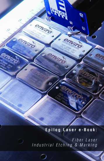
1. 2 C U S T O M I Z AT I O N A N D D E S I G N CONTENTRight:Customized lipsticksusing varnishstripping, and designpossibilitieson blue anodizedaluminum.Below:Color annealingon titanium.Graphic appliedto a car headrestusing a markinglaser.Designs onfabric andwood.
1. 2 C U S T O M I Z AT I O N A N D D E S I G N CONTENT1.2CUSTOMIZATION AND DESIGNIn the current era of Industry 4.0, flexibility is a top priorityfor many industrial applications. Everything is trendingtowards as much customization as possible and towardslot size 1 — which means marking processes have to beVolkswagen AGable to keep up. Laser marking is ideally suited for etchingcustomized features on products manufactured ina standardized manner — be these design elements oryour own name.ADVANTAGES OF LASER MARKING FORCUSTOMIZATION AND DESIGNIn recent years, lasers have become established as a highlyimportant tool for marking industrial production goods.On the one hand, this is a result of the advantages alreadymentioned with regard to flexibility, and on the otherhand due to the further developed user- friendlinessof marking systems. There are practically no limitsto the design possibilities, without havingto compromise on quality. Thanks to easyintegration into the manufacturing chain,it is also possible to incorporate customizationoptions into the series production process.Users can apply their designs to awide range of materials. The spectrum ofpossibilities becomes even greater if youincorporate additives into plastics or use ultraviolet lasers. As a result, using a laser markingsystem means you can potentially replace severalother processes in one go — and achieve betterquality at the same time.Marking on a toilet seatmade from white thermosetting plastic.
1. 3 P R O C E S S P R E PA R AT I O N A N D S U R FA C E T R E AT M E N T CONTENT1.3 PROCESS PREPARATION AND SURFACE TREATMENTUsing short-pulse lasers for tasks other than classic marking applications has been thenorm for quite a long time. Thanks to their robustness and flexibility, they can alsobe used for entirely different applications within the industry. The two most frequentareas of application in terms of marking are the treatment of surfaces for preparingsubsequent joining processes and the functionalization of all types of surfaces.WHY USE MARKING LASERS FOR PREPARING JOINING PROCESSES?Functional layers — such as insulations or coatings for protecting surfaces — can bechallenging for joining processes like laser welding, soldering, and bonding. Althoughthese can sometimes be counteracted with corresponding parameterization, this hasa negative effect on the quality of the joining process. During the welding process, theraw material of the functional layer combines with the molten metal and, thus, disturbsthe process. This can lead to spatters and inclusions. The consequences are sometimessimilar in the case of dirt layers. In the absence of an integrated laser process, it becomesnecessary to carry out complex pre- and postprocessing such as chemical cleaningor sandblasting in order to guarantee quality.In this situation, a marking laser serves as the ideal preparation tool. With short,powerful pulses, it can remove protection, oxidization and functional layers, oil, grease,and other contaminants from components just from the areas that need joining. Thismethod of localized cleaning makes the whole process very fast and ensures thatfunctional protection layers beyond the seam points remain intact. The welding processruns more homogenously, faster, and with absolute repeatability. If a marking laseris used in joining preparation, it can also apply a Data Matrix Code or serial numberto the component simultaneously. This takes care of both cleaning and traceability ina single step.At a glance — the advantages of using a marking laser as a complementarytool in joining processes:Easy integration into fully automatic production sequences, as all sequencesare carried out using computer control and because datacan be transferred very easily via interfaces.No further preparatory work or reworking necessaryOption to mark large surfacesReach areas that are difficult to accessHigh processing speedEnvironmentally friendly process
1 . 3 P R O C E S S P R E PA R AT I O N A N D S U R FA C E T R E AT M E N T CONTENTWHAT TYPES OF PROCESS PREPARATIONS ANDSURFACE TREATMENTS ARE THERE?Cleaning for welding preparationWith short and ultrashort pulses, marking lasers remove unwanted coatings from seampoints with utmost precision and without affecting the surface underneath. This leads toboth efficient processes and high-quality results in the subsequent welding stage.The advantages of welding laser-cleaned components include:Higher welding qualitySignificantly fewer spatters during the welding processFewer pore inclusions during weldingSignificantly smoother welding processLocal cleaning in a matter of seconds precisely at the seam pointsHigh reproducibility and uniform cleaning result on the surfaceReplaces time-consuming cleaning measures such as baths or sandblasting, andcan operate entirely without chemicals or other additional aids, residue-freeRemoving grease and oilIn some instances, production-related grease and oil can collect on components.It is advisable to remove these layers from the seam points to ensure a smooth andspatter-free welding process and to guarantee high-quality results. The laser lightfrom the marking laser vaporizes the dirt, affecting the surface just very slightly.ExampleA typical area of application is the removal of oil residue from tubes. In just a singlepass, the marking laser can reliably vaporize the oil from all around the two endsof the tube. The steam is transported away via a suction device and there is no needfor using compressed air.
1. 3 P R O C E S S P R E PA R AT I O N A N D S U R FA C E T R E AT M E N T CONTENTRemoving corrosion and oxidesCorrosion and other forms of oxidation on the surface distort the visual appearance,hamper any further processing (e.g. joining through bonding or welding), and restrictthe functionality. To combat these effects, the material can be vaporized with a laserand sucked away. You simply adjust the laser power to the degree of corrosion and,if necessary, pass over the area several times. A single pass removes corrosion of up to100 μm thick. Using a scanner system, the removal rate is typically up to 30 cm2/s.Cleaning moldsUsing a marking laser to clean molds enables the extensive vaporizing of just the processresidue, and without wearing away the mold. Due to laser cleaning, the industry nolonger requires the use of cleaning methods that are either energy-intensive, problematic,or cause wear, such as chemicals, dry ice, brushes, and sandblasting.Example (1)Laser cleaning can be used in the manufacturing of tires, for example. In tiremanufacturing, rubber is vulcanized in a tire mold using high pressure at 170 C. Whenremoving the tire, rubber residue and other separating agents stick to the negativeprofile of the mold. With the application of a pulsed laser, you can vaporize this residueof varying thickness in these geometrically complex forms on a regular basis.Video: “TruMicro 7050 — lasercleaning” www.trumpf.info/4lvxjy(1)(2)
1 . 3 P R O C E S S P R E PA R AT I O N A N D S U R FA C E T R E AT M E N T CONTENTDecoatingIn welding, galvanizing and applying nickel plating and anticorrosion layers can lead tospatters and pore inclusions. To ensure that the process is smooth and to guaranteehigh-quality results, it is advisable to remove these layers from the seam points. Followingthe same principle, these types of layers can also be removed locally before soldering.Example (2)Deep-drawn, custom-cut steel sheet blanks, made up of different grades of material andsheet thicknesses tailored blanks, are protected against corrosion with a 10 to 20 μmthick layer of aluminum-silicon alloy (AlSi). During welding, the protection layercauses spatters and porosity, which means that the connection is not necessarily secure.For this reason, it nevitable to target and ablate the AlSi layer from just the seam points,without affecting the base layer material underneath. Using short laser pulses makes it ispossible to ablate the layer with a processing speed of more than 5 cm2 /s.Example (3)In the automotive industry, a bevel gear is welded with the gearbox housing (powertrain)for the axle differential. Over its lifespan, this component is required to transmit immenseforces — and the demands placed upon the laser welding process are just as high.Spatters and pore inclusions from the protective phosphate coating on the bevel gearcan make the component unsuitable. For that reason, shortly before welding, a markinglaser vaporizes the phosphate coating and any oil layer right at the seam point, usingscanner optics. As the bevel gear is rotationally symmetrical, the component is turnedduring the decoating stage. Although the laser remains rigid during the process,the scanner allows the beam to oscillate, so that the desired area can be covered.(3)
1. 3 P R O C E S S P R E PA R AT I O N A N D S U R FA C E T R E AT M E N T CONTENTStrippingStripping involves the local or complete removal of color or paint, without affectingthe surface underneath. Stripping serves to increase electrical conductivity, to preparea component for a subsequent welding or bonding process, to create a windowin the case of transparent components, or to prepare a component for a recoating.Example (1)Sometimes it is only by removing the paint that a mark is created, for example onpowder coatings. The laser removes the powder coating up to the base material.RougheningRoughening involves optimizing surfaces for adhesives, injections of plastics, orthermoplastic. Laser pulses create a relief structure on the surface of the material,allowing these materials to unite, thereby creating a secure bond. As a result,the roughened surfaces support joining techniques that are of particular importancefor lightweight design and composite materials, such as CFRP: bonding and hybridform-locking bonds made of metal and plastic.(1)(2)
1 . 3 P R O C E S S P R E PA R AT I O N A N D S U R FA C E T R E AT M E N T CONTENTExample (2)The bonding of fiber composites such as CFRP involves improving the adhesiveproperties of the materials, without damaging the sensitive carbon fibers. In this case,the laser's key advantage is its precision: with a meticulously precise pulse configuration,the laser light activates the surface in just the required area and cleans it with one pass —and only to the required depth.Example (3)Form-locking bonds between metal and thermoplastics are an important elementwhen it comes to lightweight design. They are created through a high-power nanosecond laser preparing the surface of the metal joining partner for adhesion. The laserpulses create indents through engraving and material bulging — even on large adhesivesurfaces. Subsequently, the metal joining partner, or even just the joining area, is heatedup (also possible with a laser for example). The thermoplastic material flows throughthe indentations. If it is cooled, the result is a secure bond, which can also be optimizedin terms of the later flow of force. It is also possible to use this method for joiningfiber-reinforced plastics with metal.(3)1,400 μm400 μm
1. 3 P R O C E S S P R E PA R AT I O N A N D S U R FA C E T R E AT M E N T CONTENTCHANGING TRIBOLOGICAL PROPERTIESWith laser pulses, it is easy to engrave tiny structures into thematerial, either to reduce friction (for reducing wear or lubricantconsumption) or to actively increase friction (for antirotation lockingor for a higher surface pressure). In this case, the laser-inducedstructures are either cells, pockets, lines, or spirals.Example (1)Typical application areas of laser structuring for reducing frictioninclude the running surfaces of cylinders and the bearing seatsof shafts. In this case, grease lubricant cells are applied. It is alsopossible to structure the inside of tubes, whereby the laser lightshines diagonally into the tube, structuring the surface. This isfacilitated by the step-by-step adjustment of the focus level viainternal defocusing.Example (2)A typical application area of using laser structuring for increasingfriction is the bearing seat of a connecting rod in a drive.The ridge structure increases the surface pressure of the bearingshells at the large end of the connecting rod and decreasesthe risk of slipping at high torques.(1)1.0 mm
1 . 3 P R O C E S S P R E PA R AT I O N A N D S U R FA C E T R E AT M E N T CONTENT(2)100 μm
CONTENT
1. 4 MED I C AL TEC HN OLOGY CONTENT1.4 MEDICAL TECHNOLOGYPARTICULAR CHALLENGES OF THIS SECTORQualificationQuality management in the medical technology industry is strict. Amongst other things,it also comprises validating any process that occurs within the production process.One part of this validation stage involves qualifying any equipment used — known asequipment qualification (EQ). Every piece of machinery, even if it was only used onthe periphery of the production process, is checked according to the strictest technicalstandards. And of course, this is also the case for marking lasers. An equipmentqualification is usually divided into the following qualification stages:Design qualification (DQ) outlines the requirements the machinery needs to complywith and how this is to be achieved. This is often illustrated within specifications.Installation qualification (IQ) verifies whether a machine complies with thedocumented requirements, such as scope of functions, and whether it has beeninstalled correctly and all necessary accompanying documents are present.Operation qualification (OQ) verifies whether the machine functions correctlywithin the selected work environment. This stage includes checking that the system,including all its individual settings, function according to the operational specifications.Performance or process qualification (PQ) checks whether the machine carriesout the process within the process boundaries in a statistically safeguarded manner,according to the specifications.Manufacturers like TRUMPF can support customers with these qualifications, byoffering standardized packages for the IQ and OQ, for example. This gives the userthe advantage of receiving the necessary documentation straightaway.Implementing the UDI requirementsImportant markets like the US, China, and the EU place high demands on the traceability of medical technology. The key word here is unique device identification (UDI).Although the details of regulations vary, one thing is always clear: it is mandatoryfor medical products to be marked with a code that contains any relevant information(e.g. manufacturer, batch number, production date).
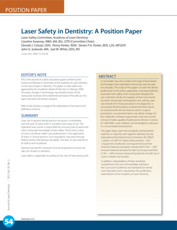
1. 4 M E D I C A L T E C H N O L O G Y CONTENT12UDI1GLOBALUDI DATABASESoftware MA7PROCGEESSING56Steps to obtaining a UDI-compliant markingStep 1: The software isconnected to databases.It is also possible toinput information into thesystem via external manualscanners, for example.Step 2: An interfaceprocesses the input dataand, for example, connectsdatabases or control systemswith the marking laser.Step 3: The UDI modulecreates the regulationscompliant code using theUDI-relevant data andindividual extensions.Step 4: An image-processingdevice recognizes the component and its position automatically. The software transmitsthe information to the control,which places the marking inthe correct position.Step 5: The laser marksthe workpiece.Step 6: Subsequently,automatic quality control iscarried out via a camera,which reads and evaluatesthe quality of the marking.Video: “UDI-conform laser marking”www.trumpf.info/tv7f8wVideo: “Success story ofour customer Miethke”www.trumpf.info/0hyjw5UDI marking onsurgical stainlesssteel and lasermarked tube.Step 7: The marked datais matched with thedatabase and saved fordocumentation purposes— with additionalinformation ifdesired.
CONTENTTraceability must be guaranteedacross the entire supply chainand the entire lifespan of theproduct. The code should be readablefor both machines and humans. It is essentialthat the user has marking software that canprovide all of the necessary features. Therefore, itmust be able to master common standards suchas GS1, HIBC, or ISBT 128 and include the necessaryinterfaces for importing all of the required data and,if necessary, also be able to reexport these for any relevantdatabase.APPLICATIONSBlack marking with ultrashort pulse lasers (USP)To meet the quality requirements that legislators around the world placeupon medical technology — providing permanent readability andcorrosion resistance — black marking has become the process of choice.Black marking involves using a laser to apply a particularly dark,contrastive marking to the surface, without removing any of the material.The ultrashort laser pulses create structures that are just nanometerswide. The rough surface — known as nanoripples — ensures that thedistribution (directed reflection) of the light is reduced and effectuates adeep blackening of the marking, which is clearly visible from any angle.Technical background of black marking in chapter 2.1The advantages of black marking at a glance: High contrast of the marking Consistent quality with large batch sizes High durability (even if sterilized hundredsof times) and clinical preparation Corrosion resistance Visible from any angle (even in brightoperating room) through matt marking
CONTENT
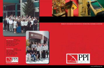
1. 5 AU TOMOT I VE CONTENT1.5 AUTOMOTIVEPARTICULAR CHALLENGES OF THIS SECTOROne of the automotive industry's key issues is using appropriate markings to guaranteeseamless traceability and ensure the clear identification of components for protectionagainst counterfeit. These are application areas in which marking lasers are often used,as they comply with the demands of the manufacturing requirements in this industry.These include:The pace is extremely high, as batch sizes can be very large, depending on the component.As a result, marking processes have to be highly productive but still run with precision.To deliver consistently high quality, the marking processes have to be stableand reproducible. The required tolerances are minimal and have to be compliedwith unconditionally.The availability and service life of the laser should be high, even if a machine hasbeen shifted a number of times, so as to recoup the often comparatively higherstart-up investment costs.Many automotive components are manufactured under difficult conditions, e.g.within the immediate proximity of foundries. As a result, the means of productionmust be able to deal with environmental factors such as high temperatures.In addition to a high degree of flexibility, the user interface has to be easy to useand intuitive. It must also be possible to carry out the set-up of different processesquickly and, ideally, without external assistance. Furthermore, less well-trainedoperators should be able to handle marking lasers reliably.Automotive companies are international companies with manufacturing processesthat are spread out across the globe. This means that the service of theirmachines should be ready to react quickly and purposefully in any country.Long-term development partnerships between manufacturers andsystem providers give rise to positive synergy effects.Traceability, protection againstcounterfeit process preparation,and design are the areas ofapplication of markinglasers.VolkswagenAG
1. 5 A U T O M O T I V E CONTENTAPPLICATIONSClear labeling for traceability and protection against counterfeitThe complex topic of traceability brings with it several application examples fromthe automotive sector. The one encountered most frequently is surely the applicationof Data Matrix Codes (DMC), although 1D bar codes are also still used. Theapplication of serial numbers, texts, logos, and certificate seals — intended forcomponent identification — also belong to the core applications in terms oftraceability.The processes that are generally used for this are engravingand — depending on the material — annealing or foaming, and colorchanging. A typical example is light / white DMCs applied onto darkplastic surfaces.This is the method used for marking almost every component in avehicle. A well-known example of this is the vehicle identificationnumber (VIN), which has a clear identification purpose. In order to protectagainst manipulation, the VIN is applied to several areas of a vehicle and isalways engraved to at least 300 µm conforming to standards, which ensuresthat it is readable at all times. A challenge for the marking process is that engravedareas are usually painted over afterwards, which is not allowed to impact negatively onthe marking quality. A great advantage of the laser here is its non-contact use, andtherefore freedom from wear, in comparison to mechanical processes such as needleengraving. Using lasers, peripheral devices such as robots are not subject to strainand their life is greatly extended. A further example for a similar type ofmarking is shift stamping. Shift stamping involves engraving data about thecomponent and the shift onto any part that comes out of the pressplants, and is how an even larger quantity of data can find its wayinto a vehicle. What all of these points have in common isthat handling the production data
AUTOMOTIVE ELECTRONICS WHITE GOODS AND CONSUMER GOODS BASICS OF LASER MARKING METAL PLASTICS OTHER NONMETALS NATURAL MATERIALS PROCESS PARAMETERS LASER BEAM GUIDANCE AND FOCUSING MARKING SYSTEMS . as suppliers for the automotive