Transcription
VWR PURANITY TU INSTRUCTION MANUALEuropean Catalogue 71-1236171-1237171-1238171-1239Puranity TU3 Puranity TU3 UV Puranity TU3 UV/UF Puranity TU6 Puranity TU6 UV Puranity TU6 UV/UF Puranity TU12 Puranity TU 12 UV Puranity TU 12 UV/UF Version: 1Issued : February, 2016
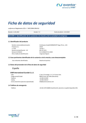
Legal Address of manufactureVWR International bvbaResearchpark Haasrode 2020Geldenaaksebaan 464B - 3001 Leuven 32 16 385011http://be.vwr.comCountry of originSweden
Technical ServiceWeb ResourcesVisit the VWR website at www.vwr.com for:Complete technical service contact informationAccess to the VWR Online Catalogue, and information about accessories and relatedproductsAdditional product information and special offersContact usFor information or technical assistance contact your local VWR representative or visitwww.vwr.com.WarrantyVWR International warrants that this product will be free from defects in material and workmanship for aperiod of two (2) years from date of delivery. If a defect is present, VWR will, at its option and cost, repair,replace, or refund the purchase price of this product to the customer, provided it is returned during thewarranty period. This warranty does not apply if the product has been damaged by accident, abuse,misuse, or misapplication, or from ordinary wear and tear. If the required maintenance and inspectionservices are not performed according to the manuals and any local regulations, such warranty turns invalid,except to the extent, the defect of the product is not due to such non-performance.Items being returned must be insured by the customer against possible damage or loss. Thiswarranty shall be limited to the aforementioned remedies. IT IS EXPRESSLY AGREED THAT THISWARRANTY WILL BE IN LIEU OF ALL WARRANTIES OF FITNESS AND IN LIEU OF THE WARRANTYOF MERCHANTABILITY.VWRPuranity TU iii
Explanatory notes on the operating instructionsEU Mark of ConformityCAUTIONIndicates a situation which, if not avoided, could result in damage to equipment or property.WARNINGIndicates a hazardous situation which, if not avoided, could result in death or seriousinjuries.DANGERIndicates a hazardous situation which, if not avoided, will result in death or serious injuries.NOTE!Is used for applicational hints and useful information.Risk of electric shock. Electrical work on the system is only to be carried out by qualifiedpersonnel.Protective conductor connectionConnect the power supply to an electrical socket with a protective connection.Indicates a situation in which protective gloves or clothing must be worn.Indicates a situation in which protective goggles must be worn.Indicates a situation in which breathing protection must be used.iv Puranity TU VWR
This information is valid for the system that is received.For quick and correct service, please include the following information on all inquiries andreplacement parts orders which relate to your system:The serial number (located on the back of the unit on the nameplate)The catalog numberCompliance with local laws and regulationsThe customer is responsible for applying for and obtaining the necessary regulatory approvals orother authorisations necessary to run or use the Product in its local environment. VWR will not beheld liable for any related omission or for not obtaining the required approval or authorisation,unless any refusal is due to a defect of the product.VWRPuranity TU v
vi Puranity TU VWR
Table of ContentsChapter 1 Transport and packaging . . . . . . . . . . . . . . . . . . . . . . . . . . . . . . . . . . . . . . . . . . . . . . . . . . . . . 1Examination on receipt . . . . . . . . . . . . . . . . . . . . . . . . . . . . . . . . . . . . . . . . . . . . . . . . . . . .1-1Complaints . . . . . . . . . . . . . . . . . . . . . . . . . . . . . . . . . . . . . . . . . . . . . . . . . . . . . . . . . . . . .1-2Packaging for return shipment . . . . . . . . . . . . . . . . . . . . . . . . . . . . . . . . . . . . . . . . . . . . . . .1-2Chapter 2 Safety precautions . . . . . . . . . . . . . . . . . . . . . . . . . . . . . . . . . . . . . . . . . . . . . . . . . . . . . . . . . . 3Chapter 3 Extend of delivery . . . . . . . . . . . . . . . . . . . . . . . . . . . . . . . . . . . . . . . . . . . . . . . . . . . . . . . . . . . 7Extend of delivery Puranity TU3 /6 . . . . . . . . . . . . . . . . . . . . . . . . . . . . . . . . . . . . . . . . . .3-7Available Puranity TU 3 /6 systems . . . . . . . . . . . . . . . . . . . . . . . . . . . . . . . . . . . . . . . . .3-8Extend of Delivery Puranity TU 12 . . . . . . . . . . . . . . . . . . . . . . . . . . . . . . . . . . . . . . . . . . .3-8Available storage tanks for Puranity TU 12 system . . . . . . . . . . . . . . . . . . . . . . . . . . . . . . .3-9Available Puranity TU 12 systems . . . . . . . . . . . . . . . . . . . . . . . . . . . . . . . . . . . . . . . . . . .3-9Chapter 4 Intended use of the device . . . . . . . . . . . . . . . . . . . . . . . . . . . . . . . . . . . . . . . . . . . . . . . . . . . 11Chapter 5 Technical specification . . . . . . . . . . . . . . . . . . . . . . . . . . . . . . . . . . . . . . . . . . . . . . . . . . . . . . 13Chapter 6 The installation area . . . . . . . . . . . . . . . . . . . . . . . . . . . . . . . . . . . . . . . . . . . . . . . . . . . . . . . . 19Chapter 7 Installation . . . . . . . . . . . . . . . . . . . . . . . . . . . . . . . . . . . . . . . . . . . . . . . . . . . . . . . . . . . . . . . 21Connections of the Puranity TU 3 /6 system . . . . . . . . . . . . . . . . . . . . . . . . . . . . . . . . . .7-21Connections of the Puranity TU 12 system . . . . . . . . . . . . . . . . . . . . . . . . . . . . . . . . . . . .7-23Connections of the pure water tank Puranity TU 12 . . . . . . . . . . . . . . . . . . . . . . . . . . . . . .7-25Bring your Puranity TU system into operation . . . . . . . . . . . . . . . . . . . . . . . . . . . . . . . . . .7-26Connecting an external tank to the Puranity TU 12 system . . . . . . . . . . . . . . . . . . . . . . . .7-29Illustration of drain . . . . . . . . . . . . . . . . . . . . . . . . . . . . . . . . . . . . . . . . . . . . . . . . . . . . . .7-30Wall mounting . . . . . . . . . . . . . . . . . . . . . . . . . . . . . . . . . . . . . . . . . . . . . . . . . . . . . . . . .7-31Mounting the power pack (voltage supply) . . . . . . . . . . . . . . . . . . . . . . . . . . . . . . . . . . . . .7-32Mounting the ball valve to the Puranity TU system . . . . . . . . . . . . . . . . . . . . . . . . . . . . . .7-34Chapter 8 Flow chart. . . . . . . . . . . . . . . . . . . . . . . . . . . . . . . . . . . . . . . . . . . . . . . . . . . . . . . . . . . . . . . . 35Chapter 9 How the Puranity TU system functions . . . . . . . . . . . . . . . . . . . . . . . . . . . . . . . . . . . . . . . . . 37Chapter 10 Initial start up . . . . . . . . . . . . . . . . . . . . . . . . . . . . . . . . . . . . . . . . . . . . . . . . . . . . . . . . . . . . 39Putting the system into operation . . . . . . . . . . . . . . . . . . . . . . . . . . . . . . . . . . . . . . . . . . .10-39Venting the 0.2 µm final filter. . . . . . . . . . . . . . . . . . . . . . . . . . . . . . . . . . . . . . . . . . . . . .10-40Chapter 11 Operating elements . . . . . . . . . . . . . . . . . . . . . . . . . . . . . . . . . . . . . . . . . . . . . . . . . . . . . . . 41Chapter 12 System control . . . . . . . . . . . . . . . . . . . . . . . . . . . . . . . . . . . . . . . . . . . . . . . . . . . . . . . . . . . 43Menu . . . . . . . . . . . . . . . . . . . . . . . . . . . . . . . . . . . . . . . . . . . . . . . . . . . . . . . . . . . . . . .12-43Mono/dual measurement mode . . . . . . . . . . . . . . . . . . . . . . . . . . . . . . . . . . . . . . . . . . . .12-43Setting the limiting value for conductivity . . . . . . . . . . . . . . . . . . . . . . . . . . . . . . . . . . . . .12-45
Setting the limiting value for temperature . . . . . . . . . . . . . . . . . . . . . . . . . . . . . . . . . . . . .12-46Error message and acoustic error signal. . . . . . . . . . . . . . . . . . . . . . . . . . . . . . . . . . . . . .12-47Communication. . . . . . . . . . . . . . . . . . . . . . . . . . . . . . . . . . . . . . . . . . . . . . . . . . . . . . . .12-48Potential-free contact . . . . . . . . . . . . . . . . . . . . . . . . . . . . . . . . . . . . . . . . . . . . . . . . . . .12-48Chapter 13 Maintenance . . . . . . . . . . . . . . . . . . . . . . . . . . . . . . . . . . . . . . . . . . . . . . . . . . . . . . . . . . . . . 49Maintenance Intervals . . . . . . . . . . . . . . . . . . . . . . . . . . . . . . . . . . . . . . . . . . . . . . . . . . .13-49Replacing the ultrapure cartridge . . . . . . . . . . . . . . . . . . . . . . . . . . . . . . . . . . . . . . . . . . .13-50Replacing the RO/pretreatment . . . . . . . . . . . . . . . . . . . . . . . . . . . . . . . . . . . . . . . . . . . .13-52Cleaning. . . . . . . . . . . . . . . . . . . . . . . . . . . . . . . . . . . . . . . . . . . . . . . . . . . . . . . . . . . . .13-53Changing the ultrafilter . . . . . . . . . . . . . . . . . . . . . . . . . . . . . . . . . . . . . . . . . . . . . . . . . .13-56UV-reactor assembly . . . . . . . . . . . . . . . . . . . . . . . . . . . . . . . . . . . . . . . . . . . . . . . . . . . .13-58Replacing the UV lamp . . . . . . . . . . . . . . . . . . . . . . . . . . . . . . . . . . . . . . . . . . . . . . . . . .13-59Replacing the 0.2 µm final filter . . . . . . . . . . . . . . . . . . . . . . . . . . . . . . . . . . . . . . . . . . . .13-61Autoclaving the 0.2 µm final filter. . . . . . . . . . . . . . . . . . . . . . . . . . . . . . . . . . . . . . . . . . .13-62Chapter 14 Equipment disposal. . . . . . . . . . . . . . . . . . . . . . . . . . . . . . . . . . . . . . . . . . . . . . . . . . . . . . . . 63Chapter 15 Trouble shooting . . . . . . . . . . . . . . . . . . . . . . . . . . . . . . . . . . . . . . . . . . . . . . . . . . . . . . . . . . 65Chapter 16 Consumables . . . . . . . . . . . . . . . . . . . . . . . . . . . . . . . . . . . . . . . . . . . . . . . . . . . . . . . . . . . . 67Accessories . . . . . . . . . . . . . . . . . . . . . . . . . . . . . . . . . . . . . . . . . . . . . . . . . . . . . . . . . .16-67Chapter 17 Terminal assignment . . . . . . . . . . . . . . . . . . . . . . . . . . . . . . . . . . . . . . . . . . . . . . . . . . . . . . 69Chapter 18 Maintenance record . . . . . . . . . . . . . . . . . . . . . . . . . . . . . . . . . . . . . . . . . . . . . . . . . . . . . . . 71Chapter 19 Your Distributor. . . . . . . . . . . . . . . . . . . . . . . . . . . . . . . . . . . . . . . . . . . . . . . . . . . . . . . . . . . 73Chapter 20 Index . . . . . . . . . . . . . . . . . . . . . . . . . . . . . . . . . . . . . . . . . . . . . . . . . . . . . . . . . . . . . . . . . . 75
Transport and packagingUltrapure water systems are carefully inspected and packed prior to shipping, but damage couldstill possibly occur during transport. Lifting and carrying the VWR Ultrapure Water System, e.g. tothe installation location, should be carried out by two people.Examination on receiptCheck the completeness of the goods received against the packing list.NOTE!Does the packaging show signs of damage? Inspect the system for damage.PackagingSystemVWRPuranity TU 1
Chapter 1 Transport and packagingComplaintsShould damage have occurred to the goods during transport:Immediately contact your delivery transport agency.Save the complete packaging, including the cardboard box, for a possible inspection of themand/or return shipment of the system.Packaging for return shipmentIf possible, use the original box and packaging material.When these are no longer available, then:Protect the system from shock by packing it in bubble wrap and/or packaging foam and astrong cardboard box.NOTE!Only a trained person should take the system out of operation.Prior to send back a operated device, empty the water and dry the system and take outthe cartridges.Pack the ultrapure cartridges into a bubble wrap and/or packaging foam and take it within into the package of the Ultrapure Water System.2 Puranity TU VWR
Safety precautionsNOTE!Observe these safety precautions for your own safety!CAUTIONThe VWR Ultrapure Water Systems are modern water purification system intended solely forthe treatment of potable water. The water it produces is not fit for drinking.DANGERWork may only be performed on the system electronics when the system has been switchedoff and when ESD protection is in place. Only specially trained personnel may work on thesystem’s electronics.Do not install or operate the system until you have carefully read through these operatinginstructions and the notes and notices contained therein.Lifting and carrying the ultrapure water system, e.g. to the installation location, should becarried out by two people. To do this, lift the system in tandem at the two corner pointsbeneath the bottom plate.The CE mark is nullified if you make any structural changes to the system or install productsfrom other manufacturers in/on the system.Protect the system from frost. The temperature at the installation area must be between 2 C and 40 C.Always observe the applicable, pertinent codes and regulations valid at the installationlocation of the system and follow all applicable accident prevention regulations.The feedwater pressure must be at least 0.1 bar and at max. 6 bar or 1.45 to 87 PSI. Whenthe feedwater pressure is higher, install an external pressure reducer.A low pressure check valve is recommended to prevent back flow of feedwater from watersystem.A grounded 100-240V, 50/60Hz electrical outlet must be available (see “Electricalconnections” on page 16).VWRPuranity TU 3
Chapter 2 Safety precautionsAccess to the power supply cord and plug may never be restricted or obstructed.Unplug the system from the power outlet for all maintenance work on the system.An atmospherically vented floor drain with a nominal diameter of at least 63 mm (2.48 inch)(DN50 tube) must be present at the installation location. If no drain is provided it isrecommended that a water detector be installed for safety reasons (for Europeanspecifications only). Failure to provide this will release the manufacturer from liability for anywater-induced damage that may result.Proceed as follows if the system is not to be operated for an extended period, e.g., overextended weekend, or during a vacation period:Switch the system off (unplug the mains plug).Close the feedwater inlet (close the feedwater tap).The pump would be damaged if the system were to run without any supply of feedwater. Themanufacturer will not accept any liability should this occur.The system must be disinfected or rinsed after an extended down time. The cleaningprocedure is described under “Cleaning” on page 53.The surface or wall on which the system is to be installed or mounted must have an adequateload-carrying capacity (check the capacity and stability of the wall). The dry weight of thesystem is given under “Dimensions and weight Puranity TU 3 /6 ” on page 14 and“Dimensions and weight of Puranity TU 12 ” on page 15.The surface on which the system is installed must be level and stable not to exceed amaximum of 2% deviation from evenness is recommended.When installing the water purification system, always ensure that there is adequate space allaround the system (see “Accessibility to Puranity TU systems and pure water tank” onpage 17.) to ensure that ease of use or easy replacement of materials (e.g., filter change,connection) is possible at all times.Visually inspect the system at regular intervals. Clean up any water or spills found around thesystem immediately.4 Puranity TU VWR
Safety precautions Chapter 2WARNINGNever look directly into a switched-on UV-lamp, as UV-light endangers eyesight!CAUTIONTo avoid the risk of pinching, crushing, cutting or electrical shock, never perform maintenanceon the system without its protective housing, or while it is in operation. Maintenance work onthe system may only be performed by trained, authorized specialists.Wear safety gloves when working with cleaning solutions.If your skin should come into contact with a chlorine product, rinse it immediately with ample,fresh water.The system, or system components, may heat up as a result of a defect. It is recommended toalways wear appropriate safety gloves to prevent skin damage or burns.Wear safety gloves when changing the UV-lamp, in order to prevent that your skin comes incontact with the UV-lamp glass.Wear safety glasses when working with cleaning solutions.If your eyes come into contact with a chlorine product, rinse them immediately with ample,fresh water and contact a physician at once.Check the UV-lamp before initial start.If the UV-lamp is broken:wear a breathing protector, filter category FFP3 and replace the UV-lamp. Fordisposal the UV-lamp refer to “Equipment disposal” on page 63.ventilate the room well.To avoid tripping, ensure that the tubings do not lay over the floor.Apply the general rules of hygiene for laboratories when working with the system.Do not use any oxidative cleaning agents for cleaning the system. These can damage thesystem.VWRPuranity TU 5
Chapter 2 Safety precautionsProceed as follows when the system has a defect:Switch the system off and unplug the system from power outlet.Shut off the feedwater supply.Contact your local service organization.6 Puranity TU VWR
Extend of deliveryExtend of delivery Puranity TU3 /6 The following items are included with the Puranity TU 3 /6 ultrapure water system:Cat. No.:1x Puranity TU 3 /6 ultrapure water system:Puranity TU3 Puranity TU3 UV Puranity TU3 UV/UF Puranity TU6 Puranity TU6 UV Puranity TU6 UV/UF 171-1231171-1232171-1233171-1234171-1235171-12361 x Ultrapure cartridge171-11411x RO/pretreatment cartridge for a 3L / h system or171-1142for a 6L / h systemincluding 1 x assembly kit171-1143171-1140consisting of:VWR1 x Final final filter (sterile filter 0.2 μm)171-11051 x Sterile vent air filter171-11661 x Feedwater connecting kit171-11451 x Connectiong tube AD 1/4“ 6 m/8.22 inch171-11461 x Ball valve 1/4“171-11471 x Cleaning adapter171-11481 x Table top power pack171-11211 x Universal adapter171-11291 x Universal holder171-11301 x Rubber connector to nema plug connector171-11311x Rubber connector to british ST plug connector171-11321x Rubber connector to euro plug connector171-11331 x Plug angle connector 1/4“171-11491 x T-connector 1/4“171-1150Puranity TU 7
Chapter 3 Extend of deliveryAvailable Puranity TU 3 /6 systemsCat. No.:System171-1231Puranity TU 3 171-1232Puranity TU 3 UV171-1233Puranity TU 3 UV/UF171-1234Puranity TU 6 171-1235Puranity TU 6 UV171-1236Puranity TU 6 UV/UFExtend of Delivery Puranity TU 12 The following items are included with the Puranity TU 12 pure water system:Cat. No.:1 x Puranity TU 12 ultrapure water system:Puranity TU12 Puranity TU12 UV Puranity TU12 UV/UF 171-1237171-1238171-12391 x Pure water tank with 30L capacity or171-117060L capacity171-11711 x Ultrapure cartridge171-11411 x RO/pretreatment cartridge171-1165including 1 x assembly kit171-1185consisting of:8 Puranity TU 1 x Final final filter (sterile filter 0.2 μm)171-11051 x Feedwater connecting kit171-11451 x Connectiong tube outer diameter 1/4“ 6 m/8.22 inch171-11461 x Ball valve 1/4“171-11471 x Cleaning adapter171-11481 x Table top power pack171-11211 x Universal adapter171-11291 x Universal holder171-11301 x Rubber connector to nema plug connector171-11311x Rubber connector to british ST plug connector171-11321x Rubber connector to euro plug connector171-11331 x Plug angle connector 1/4“171-11491 x T-connector 1/4“171-1150VWR
Extend of delivery Chapter 3Available storage tanks for Puranity TU 12 systemCat. No.:SystemCapacity171-1170Pure water tank30 liter171-1171Pure water tank60 literAvailable Puranity TU 12 systemsVWRCat. No.:System171-1237Puranity TU 12 171-1238Puranity TU 12 UV171-1239Puranity TU 12 UV/UFPuranity TU 9
Chapter 310 Extend of deliveryPuranity TU VWR
Intended use of the deviceThe VWR Ultrapure Water Systems are laboratory system and is used for treatment of water. Thesystem allows the purification of water into the water categories mentioned in the standards ofASTM 11.01 and ASTM 11.02.The system must not be operated outside of the specifications as described in the operatingmanual. In particular, the system may not be used for production of drinking water and drugsmanufacturing. The system must not be used as a medical device and outside of laboratories.VWRPuranity TU 11
Chapter 412 Intended use of the devicePuranity TU VWR
Technical specificationNOTE!Check at regular intervals the quality of your feedwater.Feedwater requirementsSourceTap waterSilt Density Index (SDI)Bacteria should be 0.01Conductivity (reference temperature 25 C)1200 μS/cm (0.0008 MΩ·cm)Free chlorinemax. 0.1 ppmManganese contentmax. 0.05 ppmIron contentmax. 0.05 ppmpH range4 - 11Temperature 2 C - 35 CPressure1 - 6 bar /14 - 87 PSI (at a pressure 6 bar / 87 PSI a pressurereducer must be installed upstream of the system.Product water quality ASTM Type I (on dispensing valve)UVUV/UFConductivity(reference temperature 25 C)μS/cm0.0550.0550.055Resistance(reference temperature 25 pg/ul------ 0.003 0.4BacteriaCFU/ml 0.01 0.01 0.01Bacterial endotoxinsEU/ml---- 0.001Particlesμm/ml 0.2 0.2 0.2Performancel/min1.01.00.6TOC valueVWRStandardPuranity TU 13
Chapter 5 Technical specificationProduct water quality ASTM Type II (tank quality)StandardUVUV/UFConductivity (reference temperature 25 C)μS/cm0.067-1.00.067-1.00.067-1.0Resistance (reference temperature 25 C)MΩ·cm15-1015-1015-10%999999Tank capacity Puranity TU 3 /6 Liter555External tank capacity Puranity TU 12 Literup to 60up to 60up to 60Retention rate for bacteria and particlesCAUTIONThe pressure hold valve for concentrate is factory adjusted. Changing of this adjustmentcauses damage to the reverse osmosis membrane in the RO/pretreatment cartridge. Onlyspecially trained personnel may adjust this pressure.Permeate and concentrate performance for Puranity TU SystemPermeateConcentratePuranity TU 3 l/h350Puranity TU 6 l/h655Puranity TU 12 l/h1260Dimensions and weight Puranity TU 3 /6 14 Puranity TU Height545 mm / 21.46 inchWidth305 mm / 12.01 inchDepth400 mm / 15.75 inchBase area277 x 372 mm /10.91 x 14.65 inchWeight including ultrapure cartridge and RO/pretreatment cartridge and full tank33 kg / 72.77 lbsVWR
Technical specification Chapter 5Dimensions and weight of Puranity TU 12 Height545 mm / 21.46 inchWidth305 mm / 12.01 inchDepth300 mm / 11.81 inchBase area277 x 372 mm /10.91 x 14.65 inchWeight including ultrapure cartridge and RO/pretreatment cartridge28 kg / 61.74 lbsDimensions and weight 30L and 60L pure water tankVWRSystem30L pure water tank60L pure water tankHeight606 mm / 23.86 inch920 mm / 36.22 inchWidthØ 388 / 15.28 inchØ 384 / 15.12 inchPuranity TU 15
Chapter 5 Technical specificationDimensions and weight 30L and 60L pure water tank30L pure water tank60L pure water tankDepthØ 388/ 15.28 inchØ 384 / 15.12 inchWeight with full capacity37,5 kg / 82.57 lbs71,5 kg / 157.66 lbs606920/36.22Systemn388/15.28n384/15.12Water connectionsFeedwater tubingTube 1/4“ outer diameterConcentrate tubingTube 1/4“ outer diameterTank Flow tubing (only Puranity TU 12 )Tank back flow tubing (only Puranity TU 12 )Tube 1/4“ outer diameterTank overflow tubing (only Puranity TU 3 /6 )Tube 1/4“ outer diameterDispenser back flow tubingDispenser flow tubingTube 1/4“ outer diameterTube jumperTube 1/4“ outer diameterFront outlet ball valveTube 1/4“ outer diameterElectrical connections16 Puranity TU Input voltageAC 100 – 240 V, 50 – 60 Hz, 5 – 3.8 AOutput voltageDC 24 V, 3.8 ASystem connectionDC 24 V, 80 WSerial InterfaceRS232Potential free contactmaximum 30V, 2AProtection classClass II (external SMPS certified as Class I)VWR
Technical specification Chapter 5Materials of parts which contact waterAdjustable pressure retaining valveNBR Acrylnitril Butadien RubberPump headNylon with glass fibreUV lampHigh-purity synthetic quartzUV housingStainless steelUltrapure cartridgePP PolypropyleneUF housingPC PolycarbonateRinsing solenoid valvePA PolyamideDispensing valvePET PolyethyleneterephthalateConductivity measuring cellPOM Polyoxymethylen, stainless steelDistributor blockPOM PolyoxymethylenConnectionsPOM PolyoxymethylenTubingsPE PolyethyleneO-RingsEPDM Ethylene propylene diene rubberAccessibility to Puranity TU systems and pure water tankSpace on left and right from the side of the systemat least 300 mm / 11.81 inchSpace to the back of the systemat least 200 mm / 7.87 inchTop spaceat least 400 mm /15.75 inchSpace to front of systemFree accessibilityAmbient conditionsDuring operationStorageOperation areaIndoor roomsIndoor roomsMaximum altitude above sea levelup to 2000 mup to 2000 mTemperature rangemin. 2 C, max 40 C, 80% rel.rH, non-condensingmin. 2 C, max. 60 C, 90% rel.rH, non condensingLine-voltage variationNot more than /- 10 % of the linevoltage-- (not applicable)Transient overvoltagesAs usually occur in the supplynetwork (overvoltage category IIacc. to IEC 60364-4-443)-- (not applicable)NOTE!The rated level of transientovervoltage is the withstandimpulse voltage acc. toovervoltage category II of IEC60364-4-443.VWRPuranity TU 17
Chapter 5 Technical specificationAmbient conditionsDuring operationStorageVentilation requirementsno special requirementsno special requirementsDegree of pollution22Airborne sound emissionSound pressure level18 Puranity TU 49 db(A)VWR
The installation areaNOTE!The operator is obliged to ensure, that the installation of the water purification unit and itsoperation are carried out in compliance with all national and international guidelines,applicable and valid for the place of installation.If necessary, measures to protect the drinking water have to be taken by installingappropriate components.Take the following criteria into consideration when selecting the installation area:Feedwater pressure (potable tap water) not less than 1 bar (14 PSI) and not greater than 6 bar (87 PSI).CAUTIONThe feedwater pressure must not be allowed to go above 6 bar. Install an additional pressurereducer when the feedwater pressure is higher.Minimum air temperature 2 CThe surface on which the system is installed must be level and stable not to exceed amaximum of 2% deviation from evenness is recommended.A smooth wall is required when the system is to be wall-mounted. Check the statics ofthe wall or standing surface. The standing or wall surface must be strong enough to holdthe system. (for system weight, see “Accessibility to Puranity TU systems and purewater tank” on page 17).CAUTIONFree gravity flow to drain must be ensured.VWRPuranity TU 19
Chapter 6 The installation areaAn atmospherically floor drain with an outside diameter of 63 mm or 2.48 inch (DN 50tube) shall be provided.Unobstructed draining of the rinsing water to the drain must be ensured.When no floor drain is available, install a water watcher to protect against water damage(available only for Europe).A check valve is recommended in the feedwater line to prevent back flow of feedwaterfrom the water system.An electric socket with protective connection must be available for connection of thesystem to the voltage supply. (see “Electrical connections” on page 16).Ample working space must be provided around the system for easy and pleasantreplacement of wear and replacement parts and for ease of operation (see “Accessibilityto Puranity TU systems and pure water tank” on page 17).Easy access for operation and control of the system.20 Puranity TU VWR
InstallationConnections of the Puranity TU 3 /6 system1112910765843VWR21Puranity TU 21
Chapter 7 Installation1. Tank overflow connector for outer diameter 1/4“ tube2. Feedwater connector for outer diameter 1/4“ tube3. Concentrate connector for outer diameter 1/4“ tube4. Dispenser back flow connector for outer diameter 1/4“ tube for additional hand dispenser5. Dispenser flow connector for outer diameter 1/4“ tube for additional hand dispenser6. Connector potential free contact 5 pins7. Power supply connector 24 V DC8. RS232 printer connection9. 1/4“ thread connector for 0.2 µm final filter10. Quick connectors for RO/pretreatment cartridge11. Quick connectors for ultrapure cartridge12. 1/4 thread connector for sterile vent filterNOTE!When you are remove the tube jumper between Pos. 4 and Pos. 5, you have the possibility toconnect additionally the accessory hand dispenser, ((171-1181) purchased separately). Thishand dispenser comes with an installation guide.22 Puranity TU VWR
Installation Chapter 7Connections of the Puranity TU 12 system1211176QWLDO1038294VWR5Puranity TU 23
Chapter 7 Installation1. 1/4“ thread connector for final filter2. Tank back flow connector for outer diameter1/4“ tube3. Tank flow connector for outer diameter 1/4“ tube4. Concentrate connector for outer diameter 1/4“ tube5. Feedwater connector for outer diameter 1/4“ tube6. Dispenser back flow connector outer diameter 1/4“ tube for additional hand dispenser7. Dispenser flow connector outer diameter 1/4“ tube for additional hand dispenser8. Optional printer connector9. Power supply connector 24V DC10. Level control connector for external pure water tank11. Quick connectors for RO/pretreatment cartridge12. Quick connectors for ultrapure cartridgeNOTE!When you remove the tube jumper between Pos. 6 and Pos. 7, you have the possibility toconnect additionally the accessory hand dispenser, ((171-1181) purchased separately). Thishand dispenser comes with an installation guide.24 Puranity TU VWR
Installation Chapter 7Connections of the pure water tank Puranity TU 12
Warranty VWR International warrants that this product will be free from defects in material and workmanship for a period of two (2) years from date of delivery. If a defect is present, VWR will, at its option and cost, repair, . system allows the purification of water into the water categories mentioned in the standards of ASTM 11.01 and ASTM .