Transcription
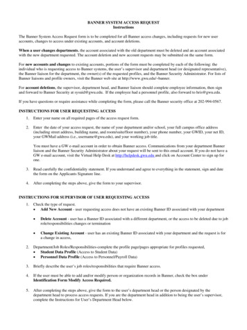
SAFETYLIGHT SCREENSCONTROLLERS &MODULESEMERGENCY STOP &STOP CONTROLLight ScreensSafety light screens protect personnel from injury and machines fromdamage by guarding points of operation, access, areas and perimeters.Type 4 safety light screens provide control reliability and high levels of faulttolerance and Type 2 safety light screens are cost effective for guardinglower-risk applications.684Courtesy of Steven Engineering, Inc. - (800) 258-9200 - sales@steveneng.com - www.stevenengineering.com
INTERLOCKSWITCHESSeriesLASER SCANNERSDescriptionMax Sensing RangeTWO-HANDCONTROLDefined AreaSafety RatingDimensionsHxWxDPowerSupplyEZ-SCREENTwo-piece system with 14 or30 mm resolution providesfinger, hand and ankledetection.page 68814 mm: 6 m30 mm: 18 m150 to 1800 mm150 to 2400 mmType 4 /Category 4/PLeH (varies by model)35 x 45.2 mm24 V dcEZ-SCREEN LPTwo-piece system with 14 or25 mm resolution providesfinger, hand and ankledetection.page 69414 or 25 mm: 7 m270 to 1810 mmType 4 /Category 4/PLeH (varies by model)28 x 26 mm24 V dcEZ-SCREEN GridsTwo-piece perimeterguarding system with upto four beams of torsodetection.page 70270 m500 to 1066 mmType 4 /Category 4/PLeH (varies by model)52 x 55 mm24 V dcEZ-SCREEN PointsTwo-piece perimeterguarding system with1 beam of torso detection.page 70370 m25 mm beam diameterType 4 /Category 4/PLe149 x 52 x 55 mm24 V dcEZ-SCREEN Type 2Suited for lower riskapplications where theresult is only a slight injury.page 70815 m150 to 1800 mmType 2 /Category 2/PLeH (varies by model)25.2 x 31.8 mm24 V dcMore information online at bannerengineering.comCourtesy of Steven Engineering, Inc. - (800) 258-9200 - sales@steveneng.com - www.stevenengineering.com685
SAFETYLIGHT SCREENSCONTROLLERS &MODULESEMERGENCY STOP &STOP CONTROLChoosing a Safety Light Screen ModelSelectHazard LevelSelectResolution12Type 4Protect personnel from injury and machines from damage by guarding points ofoperation, access, areas and perimeters. With self-checking circuitry, Type 4 lightcurtains provide control reliability and high levels of fault tolerance.Finger14 mm resolution forfinger, hand and ankledetectionSelectHousing3StandardNon-contact machineguarding systems protectfingers, hands and ankles,and guard perimetersand access, usingself-contained emittersand receivers without aseparate control box.See page 688686HandBodylower resolutionfor hand and ankledetection2, 3, or 4 beams toprotect personneland machineryLow-ProfileGrids & PointsThe space-saving,compact profile is idealfor smaller machines, yetrobust enough to meet thedemands of large powerpresses.See page 694Point and Grid systemsallow one-, two-, three- orfour-beam perimeter andaccess guarding.See page 702Courtesy of Steven Engineering, Inc. - (800) 258-9200 - sales@steveneng.com - www.stevenengineering.com
INTERLOCKSWITCHESSelectHazard LevelSelectResolution12LASER SCANNERSTWO-HANDCONTROLType 2Used for lower-risk applications, where the resultof an accident is only a slight injury. Type 2 Lightcurtains feature a large field of view and use faultexclusion to ensure the integrity of safeguarding.Hand/Body30 mm resolution for bump,bruise or knock-down detectionSelectHousing3StandardInexpensive, compactoptical safeguardingsolution designed forlower-risk applicationswhere risk of injuryis limited but someguarding is necessary.See page 708More information online at bannerengineering.comCourtesy of Steven Engineering, Inc. - (800) 258-9200 - sales@steveneng.com - www.stevenengineering.com687
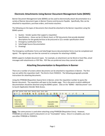
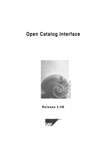
SAFETYCONTROLLERS &MODULESLIGHT SCREENSEMERGENCY STOP &STOP CONTROLEZ-SCREENSafety Light ScreensEZ-SCREEN point-of-operation systems provide finger, hand and ankledetection in a robust housing and metal endcaps. Operating range up to 18 m Displays operating status, configuration error codes, and blocked beams Exceeds OSHA/ANSI Control Reliability requirements, certified to cULusNIPF, and CE certified to Type 4, Cat 4 PLe, and SIL3 Resists impact, twisting, and abusive environments with durablealuminum housing or nickel-plated ESD-safe housing for protectionagainst electrostatic discharges Available in 14 or 30 mm resolution Cordsets and brackets see page 69114 mm Resolution30 mm ResolutionCascade14 mm resolution safety light screenscan be used for finger, hand and ankleprotection.30 mm resolution safety light screens canbe used for hand and ankle protection.Cascading models allow four systems ofany length and resolution to be connectedin a series, forming a single safety device.Some of the Available FinishesYellow PaintedAluminum688Clear AnodizedAluminumNickel-PlatedESDCourtesy of Steven Engineering, Inc. - (800) 258-9200 - sales@steveneng.com - www.stevenengineering.com
INTERLOCKSWITCHESTWO-HANDCONTROLLASER SCANNERSEZ-SCREEN Systems, 14 mm Resolution Model Key, 24 V DCModel StyleResolutionDefined AreaP14150E EmitterR ReceiverP Pair ***14 14 mmHousing ResponseLengthTime†150* 262 mm 11 msSLSSLS Light ScreenSLSC CascadingLight h 372 mm15 ms 522 mm19 ms 671 mm23 ms 821 mm27 ms 971 mm32 ms 1120 mm36 ms 1270 mm40 ms 1420 mm43 ms 1569 mm48 ms 1719 mm52 ms 1869 mm56 msResolutionDefined AreaP30150E EmitterR ReceiverP Pair ***30 30 mmSLSSLS Light ScreenSLSC CascadingLight Screen150* 02400ConnectionEmitter/ReceiverPair***orBlank Yellow powder coatN Nickel-plated ESD**A Clear Anodized AluminumS Nickel-plated (silver)EZ-SCREEN Systems, 30 mm Resolution Model Key, 24 V DCModel StyleExample Model Number SLSP14-150Q88Q8 8-pin QDP8 8-pin Pigtail QD 372 mm11 ms 522 mm13 ms 671 mm15 ms 821 mm17 ms 971 mm19 ms 1120 mm21 ms 1270 mm23 ms 1420 mm25 ms 1569 mm27 ms 1719 mm30 ms 1869 mm32 ms 2018 mm34 ms 2168 mm36 ms 2318 mm38 ms 2468 mm40 msQ88 Emitter with 8-pin QDReceiver with 8-pin QDP88 Emitter with 8-pin pigtail QDReceiver with 8-pin pigtail QDExample Model Number **orHousing ResponseLengthTime †262 mm 9 msQ88Blank Yellow powder coatN Nickel-plated ESD**A Clear Anodized AluminumS Nickel-plated (silver)Q8 8-pin QDP8 8-pin Pigtail QDQ88Q88 Emitter with 8-pin QDReceiver with 8-pin QDP88 Emitter with 8-pin pigtail QDReceiver with 8-pin pigtail QDFor more specifications see page 692.QD models: A model with a QD requires a mating cordset (see page 691).For an emitter with TEST function, replace Q8 with Q5 on emitter model numbers (example, SLSE14-150Q5) and Q88 with Q85 on pair model numbers (example, SLSP14-150Q85).For a 5-pin 300 mm M12/Euro pigtail QD with No EDM or TEST functions, replace Q8 with P5NT on emitter or receiver (example, SLSE14-150P5NT) and Q88 with P55NT on pair model numbers (example, SLSP14-150P55NT).For a 4-pin 300 mm M12/Euro pigtail QD with no EDM or TEST functions (GND/PE via mounting), replace Q8 with P4NT or Q88 with P44NT (example, SLSP14-150P4NT or SLSP14-150P44NT).*150 mm not available in cascade models** ESD-safe models are not available with the pigtail QD option*** A pair includes an emitter and receiver (example, SLSP30-150Q88)† Cascading system response time: To the response time of the slowest pair, add 2 ms for each additional pair.Example: slowest pair’s response time is 15 ms, and the system has three additional pairs (four pairs total), so the system maximum response time is 15 ms 6 ms (3 pairs x 2 ms) 21 ms.Contact Banner Engineering Corp. for additional information and/or verification of valid kit model numbers.More information online at bannerengineering.comCourtesy of Steven Engineering, Inc. - (800) 258-9200 - sales@steveneng.com - www.stevenengineering.com689
SAFETYCONTROLLERS &MODULESLIGHT SCREENSEMERGENCY STOP &STOP CONTROLEZ-SCREEN V-SeriesType 4 Safety Light ScreensThe V-Series Safety Light Screens require no configuration and are pre-configured forTrip Output, Scan Code 1, and 2-Channel EDM. Provides external device monitoring (EDM) that can be deselected via wiring hookup Operating range up to 18 m Displays operating status, configuration error codes, and blocked beams Exceeds OSHA/ANSI Control Reliability requirements, certified to cULus NIPF, andCE certified to Type 4, Cat 4 PLe, and SIL 3 Resists impact, twisting and abusive environments with a durable aluminum housingand metal endcapsEZ-SCREEN V-Series Systems, 30 mm Resolution Model Key, 24 V DCExample Model Number SLSVAP30-150Q88Model StyleResolutionDefined Area150SLSVAP30SLSVA V-series SafetyLight ScreenE EmitterR ReceiverP Pair †30 30 mmConnectionEmitter/ReceiverPair †orQ8 8-pin g ResponseLengthTime 262 mm 9 ms 372 mm11 ms 522 mm13 ms 671 mm15 ms 821 mm17 ms 971 mm19 ms 1120 mm21 ms 1270 mm23 ms 1420 mm25 ms 1569 mm27 ms 1719 mm30 ms 1869 mm32 msQ88 Emitter with 8-pin QDReceiver with 8-pin QDFor more specifications see page 692.QD models: A model with a QD requires a mating cordset (see page 691).†A pair includes an emitter and receiver (example, SLSVAP30-150Q88)Contact Banner Engineering Corp. for additional information and/or verification of valid kit model numbers.690Q88Courtesy of Steven Engineering, Inc. - (800) 258-9200 - sales@steveneng.com - www.stevenengineering.com
INTERLOCKSWITCHESTWO-HANDCONTROLLASER SCANNERSCordsetsEuro QDEuro QD—Double-EndedEuro QD Adaptor*See page 911See page 912See page 9128-Pin QDLengthStraight4.57 mQDE-815D7.62 mQDE-825D8-Pin QDLengthQDE-850D15.3 mQDE-875D22.9 mQDE-8100D30.5 mStraight0.31 mDEE2R-81D0.91 mDEE2R-83D2.44 mDEE2R-88D4.57 mDEE2R-815D7.62 mDEE2R-825D15.3 mDEE2R-850D22.9 mDEE2R-875D30.5 mDEE2R-8100DLengthEuro QD SplitterSee page 800.30 mCSB-M1281M12812.50 mCSB-M1288M12814.60 mCSB-M12815M12817.60 mCSB-M12825M12817.60 mCSB-UNT825M12810.31 mDEE8-41DDEE8-51D2.44 mDEE8-48DDEE8-58D4.57 mDEE8-415DDEE8-515D7.62 mDEE8-425DDEE8-525D* For SLS/SLP sensors with Q8 or P8 connection to safetyBUS gateway/node, “smart” self-monitored safety module,safety controller or safety PLC see page 912.Additional cordset information available.See page 9028-Pin QD8-Pin/4-PinStraightNOTE: See page 707 for interfacing solutions.Additional accessories are listed on page 844.BracketsOther AccessoriesCascadeStandsMirrorsInterfaceSee page 89414 & 30 mmSee page 894See page 895See page 895See page 944See page 948See page ional brackets and information available.See page “Banner Bracket Selection Chart”on page 852.* Standard brackets included with emitter/receiver.Replacement PartsModelDescriptionEZA-ADE-1Copolyester access cover with label for 14 or 30 mm resolution emittersEZA-ADE-2Copolyester access cover with inverted label for 14 or 30 mm resolution emittersEZA-ADR-1Copolyester access cover with label for 14 or 30 mm resolution receiverEZA-ADR-2Copolyester access cover with inverted label for 14 or 30 mm resolution receiverEZA-MBK-12Center bracket kit (includes 1 bracket and hardware to mount to MSA Series stands) for 14 or 30 mm resolution EZ-SCREENEZA-MBK-11Standard bracket kit with hardware (includes 2 end brackets and hardware to mount to MSA Series stands) for 14 or 30 mm resolution EZ-SCREENEZA-TP-1Access cover security plate (includes 2 screws, wrench) for 14 or 30 mm resolution EZ-SCREENEZA-RR-1External normally open reset switch with 8-pin/M12 Euro-style QDMGA-K-1Replacement key for switch MGA-KS0-1MGA-KS0-1Panel-mount keyed normally open reset switchEZA-HK-1Wrench, SecurityEZA-RTP-1Terminator plug for cascade receiverSTP-1314 mm test piece (14 mm resolution systems)STP-1430 mm test piece (14 mm resolution systems with 2-beam Reduced Resolution and for 30 mm resolution systems)STP-1560 mm test piece (30 mm resolution systems with 2-beam Reduced Resolution)NOTE: See Installation manual p/n 112852 for complete list of replacement parts and accessories.More information online at bannerengineering.comCourtesy of Steven Engineering, Inc. - (800) 258-9200 - sales@steveneng.com - www.stevenengineering.com691
SAFETYLIGHT SCREENSCONTROLLERS &MODULESEMERGENCY STOP &STOP CONTROL45.2 mmL36.0 mmEZ-SCREEN SystemsEZ-SCREEN 14 & 30 mm Resolution and V-Series SpecificationsSupply Voltage at the Device24 V dc 15% (use a SELV-rated supply according to EN IEC 60950)(The external voltage supply must be capable of buffering brief mains interruptions of 20 ms, as specified in EN/IEC 60204-1.)Residual Ripple 10% maximumSupply CurrentEmitter: 100 mA max., 40 mA at 24 V dc typicalReceiver: 275 mA max., 160 mA at 24 V dc typical, exclusive of OSSD1 and OSSD2 loads (up to an additional 0.5A each) andAUX output load (up to 75 mA)Response Time9 to 56 milliseconds (see model number tables)Cascade Safety Stop Interface (CSSI): 40 milliseconds max.Remote Test Input(Optional – available only onmodel SLSE.-.Q5 emitters)Test Mode is activated either by applying a low signal (less than 3 V dc) to emitter TEST #1 terminal for a minimum of50 milliseconds, or by opening a switch connected between TEST #1 and TEST #2 for a minimum of 50 milliseconds.Beam scanning stops to simulate a blocked condition. A high signal at TEST #1 deactivates Test Mode.High signal: 10 to 30 V dcLow signal: 0 to 3 V dcInput current: 35 mA inrush, 10 mA max.Wavelength of Emitter ElementsInfrared LEDs, 950 nm at peak emissionRecovery Time–Blocked to clear(OSSDs turn ON; varies with totalnumber of sensing beams andwhether Sync beam is blocked)Beam 1 (Sync Beam)All Other Beams14 mm Models109 to 800 ms33 to 220 ms30 mm Models81 to 495 ms25 to 152 msEDM Input 24 V dc signals from external device contacts can be monitored (one-channel, two-channel or no monitoring) via EDM1 andEDM2 terminals in the receiverHigh signal: 10 to 30 V dc at 30 mA typicalLow signal: 0 to 3 V dcReset InputThe Reset input must be high for 0.25 to 2 seconds and then low to reset the receiverHigh signal: 10 to 30 V dc at 30 mA typicalLow signal: 0 to 3 V dcSafety Outputs (OSSDs)Two redundant solid-state 24 V dc, 0.5 A max. sourcing OSSD (Output Signal Switching Device) safety outputs. (Use optional interfacemodules for ac or larger dc loads.)Capable of the Banner “Safety Handshake”ON-State voltage: Vin-1.5 V dcOFF-State voltage: 1.2 V dc max. (0-1.2 V dc)Max. load capacitance: 1.0 µFMax. load inductance: 10 HLeakage current: 0.50 mA maximumCable resistance: 10 Ω maximumOSSD test pulse width: 100 to 300 microsecondsOSSD test pulse period: 10 to 27 milliseconds (varies with number of beams)Switching current: 0-0.5 AAuxiliary (Aux.) Output SwitchingCapacity692Closed switch time: 0.25 to 2 secCurrent-sourcing (PNP) solid-state output, 24 V dc at 75mA max that follow the safety outputs (lockout function optional)Courtesy of Steven Engineering, Inc. - (800) 258-9200 - sales@steveneng.com - www.stevenengineering.com
INTERLOCKSWITCHESLASER SCANNERSTWO-HANDCONTROLEZ-SCREEN 14 & 30 mm Resolution and V-Series Specifications(cont’d)Controls and AdjustmentsEmitter:Scan Code selection: 2-position switch (code 1 or 2). Factory default position is code 1Receiver:Scan Code selection: 2-position switch (code 1 or 2). Factory default position is code 1Trip/Latch Output selection: Redundant switches. Factory default position is T (Trip).EDM/MPCE monitor selection: 2-position switch selects between 1- or 2-channel monitoringFactory default position is 2Reduced Resolution (2-beam Floating Blanking): Redundant switches. Factory default is OFFShort Circuit ProtectionAll inputs and outputs are protected from short circuits to 24 V dc or dc commonElectrical Safety Class(IEC 61140)IIIOperating Range14 mm models: 0.1 m to 6 m30 mm models: 0.1 m to 18 mRange decreases with use of mirrors and/or lens shields:Lens shields – approximately 10% less range per shieldGlass-surface mirrors – approximately 8% less range per mirrorSee Accessory section for more information on a specific mirror, page 692.Ambient Light Immunity 10,000 lux at 5 angle of incidenceStrobe Light ImmunityTotally immune to one Federal Signal Corp. “Fireball” model FB2PST strobeEffective Aperture Angle (EAA)Meets Type 4 requirements per IEC 61496-2, 2.5 @ 3 mEnclosureMaterials: Extruded aluminum housing with yellow polyester powder (optional black or white or nickel-plated silver finish) and well-sealed,rugged die-cast zinc end caps, acrylic lens cover, copolyester access cover. Endcaps on silver models are also nickel-plated.Rating: IP65Operating ConditionsTemperature: 0 to 55 CRelative humidity: 95% (non-condensing)Status IndicatorsEmitter:One Bi-color (Red/Green) Status Indicator – indicates operating mode, Lockout or power OFF condition7-segment Diagnostic Indicator (1 digit) – indicates proper operation, scan code or error codeReceiver:Yellow Reset Indicator – indicates whether system is ready for operation or requires a resetBi-Color (Red/Green) Status Indicator – indicates general system and output statusBi-Color (Red/Green) Zone Status Indicators – indicates condition (clear or blocked beam) of a defined group of beams7-Segment Diagnostic Indicator (3-digit) – indicates proper operation, scan code or error code, total number of blocked beamsMounting HardwareEmitter and receiver each are supplied with a pair of swivel end-mounting brackets. Models longer than 900 mm also include a swivelcenter-mount bracket. Mounting brackets are 8-gauge cold-rolled steel, black zinc finish.Shock and VibrationEZ-SCREEN components have passed vibration and shock tests according to IEC 61496-1. This includes vibration (10 cycles) of 10-55 Hz at0.35 mm single amplitude (0.70 mm peak-to-peak) and shock of 10 g for 16 milliseconds (6,000 cycles).Design StandardsDesigned to comply with Type 4 per IEC 61496; Category 4 PLe per EN ISO 13849-1;SIL 3 per IEC 61508, SIL CL 3 per IEC 62061; Type 4 per UL 61496-1/-2CertificationsMore information online at bannerengineering.comCourtesy of Steven Engineering, Inc. - (800) 258-9200 - sales@steveneng.com - www.stevenengineering.com693
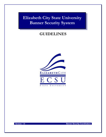
SAFETYLIGHT SCREENSCONTROLLERS &MODULESEMERGENCY STOP &STOP CONTROLEZ-SCREEN Low-Profile (LP)Type 4 Safety Light ScreensThe Low-Profile Safety Light Screen provides a small, compact design withend-to-end sensing. Operating range up to 7 m Features seven-segment display for diagnostic information andnumber of blocked beams Offers reduced resolution and fixed blanking to ignore tooling orconstant inflow of materials Identifies clear and blocked beams using zone indicators Exceeds OSHA/ANSI Control Reliability requirements, certified to cTUVus, and CEcertified to Type 4, Cat 4 PLe, and SIL 3 Cordsets and brackets see page 69814 mm Resolution25 mm ResolutionCascading14 mm resolution safety light screenscan be used for finger, hand and ankleprotection.25 mm resolution safety light screens canbe used for hand and ankle protection.Low-profile cascading models allow foursystems of any length and resolution tobe connected in a series, forming a singlesafety device.Yellow PaintedAluminum694Clear AnodizedAluminumNickel-PlatedESDCourtesy of Steven Engineering, Inc. - (800) 258-9200 - sales@steveneng.com - www.stevenengineering.com
INTERLOCKSWITCHESTWO-HANDCONTROLLASER SCANNERSEZ-SCREEN Low-Profile Systems, 14 mm Resolution Model Key, 24 V DCModel StyleResolutionDefined AreaP14270E EmitterR ReceiverP Pair ***14 14 mmSLPSLP Light ScreenSLPC CascadingLight rHousing ResponseLengthTime† 270 mm 10.5 ms 410 mm 13.5 ms 549 mm 16.5 ms 689 mm 19.5 ms 829 mm 22.5 ms 969 mm 25.5 msBlank Yellow powder coatN Nickel-plated ESD**A Clear Anodized AluminumSLP Light ScreenSLPC CascadingLight ScreenBlank Receiver with Integral RDEmitter with Integral RDP88 Receiver with 8-pin pigtail QDEmitter with 8-pin pigtail QDRD Removable disconnect 1248 mm 31.5 ms 1388 mm 34.5 ms 1528 mm 37.5 ms 1667 mm 40.5 ms 1807 mm 43.5. msDefined AreaP25270E EmitterR ReceiverP Pair ***25 25 mm270*410550690830970111012501390153016701810Blank Integral RDP8 8-pin Pigtail QDP88 1108 mm 28.5 nishEZ-SCREEN Low-Profile Systems, 25 mm Resolution Model Key, 24 V DCModel StyleExample Model Number **orHousing ResponseLengthTime† 270 mm 8 ms 410 mm9.5 ms 549 mm11 ms 689 mm 12.5 ms 829 mm 969 mm 15.5 ms 1108 mmExample Model Number SLPP25-270P88Blank Yellow powder coatN Nickel-plated ESD**A Clear Anodized AluminumBlank Integral RDP8 8-pin Pigtail QD14 msP88Blank Receiver with Integral RDEmitter with Integral RDP88 Receiver with 8-pin pigtail QDEmitter with 8-pin pigtail QDRD Removable disconnect17 ms 1248 mm 18.5 ms 1388 mm20 ms 1528 mm21 ms 1667 mm 22.5 ms 1807 mm24 msFor more specifications see page 698.QD models: A model with a QD requires a mating cordset (see page 698).QD models: Pigtail QD models require mating cordsets with an 8-pin M12/Euro-style connector (such as QDE-8.D, DEE2R-8.D or CSB-M128.M1281; see page 698).Integral RD models require mating cordsets with a removable disconnect connector (such as RDLP-8.D or DELPE-8.D; see page 698).* 270 mm not available in cascade models** ESD-safe models are not available with the pigtail QD option*** A pair includes an emitter and receiver (example, SLSP30-150Q88)† Cascading system response time: To the response time of the slowest pair, add 2 ms for each additional pair.Example: slowest pair’s response time is 15 ms, and the system has three additional pairs (four pairs total), so the system maximum response time is 15 ms 6 ms (3 pairs x 2 ms) 21 ms.Contact Banner Engineering Corp. for additional information and/or verification of valid kit model numbers.More information online at bannerengineering.comCourtesy of Steven Engineering, Inc. - (800) 258-9200 - sales@steveneng.com - www.stevenengineering.com695
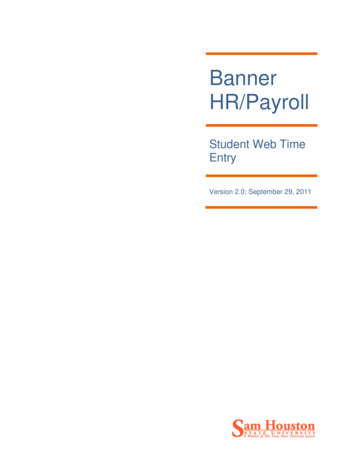
SAFETYLIGHT SCREENSCONTROLLERS &MODULESEMERGENCY STOP &STOP CONTROLEZ-SCREENLow-Profile (LP) with MutingType 4 Safety Light ScreensThe EZ-SCREEN with Muting has a built-in muting function with no third box required. Eight pre-defined muting configuration options including Bypass, Mute-DependentOverride, Mute Enable, and Mute-cycle time extensions (four seconds) for “L”-stylecell exit applications Mute Lamp and Status Outputs to EZ-LIGHT (or other indicating devices) Lower power consumption allows for energy savings and fewer/smaller power supplies Exceeds OSHA/ANSI Control Reliability requirements, certified to cTUVus, and CEcertiffed to Type 4, Cat 4 PLe, and SIL 3 Cordsets and brackets see page 698EZ-SCREEN Low-Profile with Muting Systems, 14 and 25 mm Resolution Model Key, 24 V DCExample Model Number SLPMP14-410P128Model StyleResolutionSLPMPDefined Area14SLPE EmitterSLPMR MutingReceiverSLPMP Muting LPPair14 14 mm25 25 0830970111012501390153016701810orHousing ResponseResponseLength Time(14 mm) Time(25 mm) 410 mm 13.5 ms9.5 ms 549 mm16.5 ms111 ms 689 mm19.5 ms12.5 ms 829 mm22.5 ms14 ms 969 mm25.5 ms15.5 ms 1108 mm28.5 ms17 ms 1248 mm31.5 ms18.5 ms 1388 mm34.5 ms20 ms 1528 mm37.5 ms21 ms 1667 mm40.5 ms22.5 ms 1807 mm43.5. ms24 msBlank Yellow powder coatN Nickel-plated ESDA Clear Anodized AluminumP128Blank Integral RDBlank Receiver with Integral RDP8 8-pin Pigtail QDEmitter with Integral RD(SLP Emitter)P128 Emitter with 8-pin pigtail QDP12 12-pin Pigtail QDReceiver with 12-pin pigtail QD(SLPM Receiver)(SLPM Receiver)RD Removable disconnectFor more specifications see page 700.QD models: A model with a QD requires a mating cordset (see page 698).QD models: Pigtail QD models require mating cordsets with an 8 or 12-pin M12/Euro-style connector (such as QDE-8.D, QDE-12.E, DEE2R-8.D; see page 698).Integral RD models require mating cordsets with a removable disconnect connector (such as RDLP-8.D or RDLP-11.E; see page 698).*A pair includes an emitter and receiver (example, SLPMP14-410P128)Contact Banner Engineering Corp. for additional information and/or verification of valid model numbers.696Courtesy of Steven Engineering, Inc. - (800) 258-9200 - sales@steveneng.com - www.stevenengineering.com
INTERLOCKSWITCHESLASER SCANNERSEZ-SCREEN LPM Cordset Overview*Muting Splitter CordsetsTWO-HANDCONTROLEZ-SCREEN Muting IndicatorsTL50WQSingle Color (White)3-Branch modelsBanner sensors (PNP)DELPEF-40DSingle Color Cordset 0.05 mCSM3DO-M12121FM12121MDark Operate (pin 2)DELPEF-41DSingle Color Cordset 0.3 mCSM3LO-M12121FM12121MLight Operate (pin 4)DELPEF-43DSingle Color Cordset 1 m4-Branch models (With Emitter hookup)K50LGRW2PQ-18886Three Color (Green/Red/White)CSM4DO-M12121FM12121MDark Operate (pin 2)TL50GYRWQFour Color (Green/Yellow/Red/White)CSM4LO-M12121FM12121MLight Operate (pin 4)DELPEF-50DMulti-Color Cordset 0.05 mMuting Sensor Cordsets (C & D)LengthDELPEF-51DMulti-Color Cordset 0.3 mDEE2R-51D0.3 m (1’)DELPEF-53DMulti-Color Cordset 1 mDEE2R-53D1 m (3’)LPA-MBK-15Optional mounting bracket(Used with DELPEF-.0D cordset)DEE2R-58D2.5 m (8’)DEE2R-815D4.5 m (15’)“A” (Receiver cordset): On RD models DELPE-12xxE; On P12 models cordset “A” is a preinstalled DELPE-121E.“B”: Machine interface cordset QDE-12xxE.“C” and “D”: Muting Sensor cordsets DEE2R-515D. Ensure sensors connected to Cordsets C & D are PNP output withDark Operate on pin 2 or Light Operate on pin 4.“E” (Emitter cordset): On RD models DELPE-12xxE; On P8 models (shown), use a DEE2R-8xxD double-ended cordset.If using a 3-Branch Muting Splitter cordset, use appropriate Emitter cordset.“F”: QS18VP6LPQ8 (4-pin M12/Euro QD) sensor shown as example. Other sensors or switches may be used.* Note: See EZ-SCREEN Low Profile with Muting manual (p/n 150216) for complete information.Additional Indicators available, see EZS LPM manual26 mmVaries by modelsee data sheet28 mmEZ-SCREEN LP SystemsMore information online at bannerengineering.comCourtesy of Steven Engineering, Inc. - (800) 258-9200 - sales@steveneng.com - www.stevenengineering.com697
SAFETYLIGHT SCREENSCONTROLLERS &MODULESEMERGENCY STOP &STOP CONTROLCordsetsFor use with models with integral RD connections. All standard cordsets are yellow PVC with black overmold.For black PVC cable and overmold, add suffix B to model number (example, RDLP-815DB).RDRD to Euro QD**See page 916See page 916Length8-Wire*4.57 mRDLP-815DRDLP-1115E7.62 mRDLP-825DRDLP-1125ERDLP-850D15.2 mRDLP-875D22.9 m11-WireRDLP-1150ERDLP-1175ERDLP-8100D RDLP-11100E30.5 mRD to RDSee page 917Length8-Pin Male12-Pin Male8-Pin FemaleLengthCascade0.31 mDELPE-81DDELPE-121EDELPEF-81D0.05 mDELP-110E0.30 mDELP-111E0.91 mDELP-113E2.44 mDELP-118E4.57 mDELP-1115E7.62 mDELP-1125E0.91 mDELPE-83DDELPE-123EDELPEF-83D2.44 mDELPE-88DDELPE-128EDELFEF-88D4.57 mDELPE-815DDELPE-1215EDELPEF-815D7.62 mDELPE-825DDELPE-1225E—15.2 mDELPE-850DDELPE-1250E—15.2 mDELP-1150E22.9 mDELPE-875DDELPE-1275E—22.9 mDELP-1175E30.5 mDELPE-8100D DELPE-12100E—30.5 mDELP-11100E* For connection of E-Stop or other hard/relay contacts see page 916 .** Requires mating 8-pin M12/Euro cordset. 8-pin Male used for Machine Interface connection(indicator end of sensor). 8-pin Female used for cascade connection when using M12/Euro QDs.See page 697 for EZ-SCREEN LPM cordset overview.For use with models withPigtail QD and DELPE-8xxD connections.Euro QD–Double-EndedEuro QDEuro QD SplitterSee page 912See page 911See page 914Length8-Pin*Length8-Pin12-Pin0.31 mDEE2R-81D4.57 mQDE-815DQDE-1215E0.91 mDEE2R-83D2.44 mDEE2R-88D4.57 mDEE2R-815D7.62 mDEE2R-825D15.2 mDEE2R-850D22.9 mDEE2R-875D30.5 mDEE2R-8100D7.62 mQDE-825DQDE-1225E15.3 mQDE-850DQDE-1250E22.9 mQDE-875DQDE-1275E30.5 0 mCSB-M1281M12812.50 mCSB-M1288M12814.60 mCSB-M12815M12817.60 mCSB-M12825M12817.60 mCSB-UNT825M1281* For connection to safety BUS gateway/node, a “smart” self-monitoredsafety module, safety controller or safety PLC see page 912.Additional cordset information available.See page 902Note: See page 707 for interfacing solutions, additional accessories are listed on page 844.BracketsLow-Profile 14 & 25 mmLow-Profile 14 & 25 mm–CascadeSee page 896See page 896See page 897See page 898See page 898See page 898See page 897See page BK-21LPA-MBK-90LPA-MBK-120LPA-MBK-135Additional brackets and information available.See page “Banner Bracket Selection Chart”on page 852.* Standard brackets included with emitter/receiver.698Courtesy of Steven Engineering, Inc. - (800) 258-9200 - sales@steveneng.com - www.stevenengineering.com
INTERLOCKSWITCHESLASER SCANNERSTWO-HANDCONTROLOther AccessoriesStandsMirrorsInterfaceSee page 944See page 948See page 962Remote Fixed Blanking SwitchAllows frequent configurationof a fixed blanked area, withoutusing the receiver DIP switches.EZA-RBK-1Replacement PartsModelDescriptionSTP-1314 mm test piece (for 14 mm resolution systems)STP-1625 mm test piece (for 25 mm resolution systems)STP-1734 mm test piece (for 14 mm resolution systems with 2-beam reducedresolution enabled)STP-1865 mm test piece (for 25 mm resolution systems with 2-beam reducedresolution enabled)LPA-TP-1Terminator plug, for SLPC. emitter/receiver (included with sensor)EZA-RR-1External normally open reset switch with 8-pin M12/Euro-style QDMGA-KSO-1Panel-mount keyed normally open reset switchModelDescriptionMGA-K-1Replacement key for switch MGA-KSO-1DELPE-81DReplacement for M12-terminated pigtail QD, as shipped with standard pigtail QDmodels; 8-conductor cable, 22 AWG; 0.3 m longLPA-MBK-11End-cap bracket kit (includes 2 end brackets and hardware to mount one sensorto MSA series stands; 360 sensor rotation; 14 ga (1.9 mm) steel, black zincplated; die-cast zinc end-cap plateLPA-MBK-12Side-mount bracket kit (includes 1 bracket and hardware to mount to MSASeries stands; 10 / 30 sensor rotation;14 ga (1.9 mm) steel, black zinc plated; die-cast zin
Light Screens Safety light screens protect personnel from injury and machines from damage by guarding points of operation, access, areas and perimeters. Type 4 safety light screens provide control reliability and high levels of fault tolerance and Type 2 safety light screens