Transcription
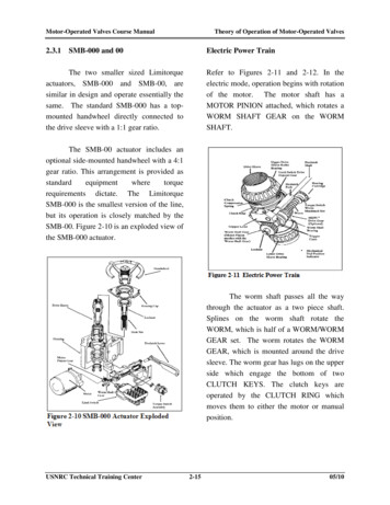
Motor-Operated Valves Course Manual2.3.1Theory of Operation of Motor-Operated ValvesElectric Power TrainSMB-000 and 00Refer to Figures 2-11 and 2-12. In theelectric mode, operation begins with rotationof the motor. The motor shaft has aMOTOR PINION attached, which rotates aWORM SHAFT GEAR on the WORMSHAFT.The two smaller sized Limitorqueactuators, SMB-000 and SMB-00, aresimilar in design and operate essentially thesame. The standard SMB-000 has a topmounted handwheel directly connected tothe drive sleeve with a 1:1 gear ratio.The SMB-00 actuator includes anoptional side-mounted handwheel with a 4:1gear ratio. This arrangement is provided asstandardequipmentwheretorquerequirements dictate. The LimitorqueSMB-000 is the smallest version of the line,but its operation is closely matched by theSMB-00. Figure 2-10 is an exploded view ofthe SMB-000 actuator.The worm shaft passes all the waythrough the actuator as a two piece shaft.Splines on the worm shaft rotate theWORM, which is half of a WORM/WORMGEAR set. The worm rotates the WORMGEAR, which is mounted around the drivesleeve. The worm gear has lugs on the upperside which engage the bottom of twoCLUTCH KEYS. The clutch keys areoperated by the CLUTCH RING whichmoves them to either the motor or manualposition.USNRC Technical Training Center2-1505/10
Motor-Operated Valves Course ManualTheory of Operation of Motor-Operated Valvescontinue until the limit switch engages andstops the motor.In a failure mode this valve actionwill continue until the torque switch, manualstop, or motor overloads stop motor rotation,until the motor burns out, or the actuator orvalve breaks. Table 2-3 outlines theSMB-000 Electric Mode Power Train.Manual Power TrainThe SMB-000 actuator is providedwith only a top-mounted handwheelassembly. The SMB-00 is available in botha side-mounted (Figure 2-13) andtop-mounted assembly (Figure 2-14). TheSMB-00 actuator is provided with aside-mounted handwheel with a 4.38:1 ratiowhen the actuator torque rating is greaterthan 65 foot pounds.As the clutch keys are driven, theydrive the DRIVE SLEEVE which hasinternal splines. Those internal splines rotatethe STEM NUT which can be threaded,splined, or keyed. The stem nut rotatesaround the valve stem or input shaft and thevalve will be repositioned by the motion ofthe valve stem. In normal operation, this willUSNRC Technical Training Center2-1605/10
Motor-Operated Valves Course ManualTheory of Operation of Motor-Operated ValvesFrom this point the power train inmanual matches the power train in electricand the effect on the valve is the same. Theonly thing that protects the valve in thiscase, however, is a well-trained operator.SMB-000/00 Declutch MechanismRefer to Figures 2-16 and 2-17. Inorder for the actuator to operate in manual,the DECLUTCH LEVER must be pressed.This rotates the DECLUTCH SHAFT,which rotates the DECLUTCH FORK. Thedeclutch fork is engaged in the CLUTCHRING, which is lifted from its normalposition next to the worm gear, to a higherposition inside the actuator. This lifts theCLUTCH KEYS, which are mounted on theclutch ring, into engagement with theHANDWHEEL LUGS.Refer to Figure 2-15 and Table 2-4. Inmanual operation, the HANDWHEELrotates in the housing cap. The handwheelhas lugs machined into the face which islocated against the end of the drive sleeve.The lugs are positioned so that the CLUTCHKEYS, (on left side of Figure 2-15) whichare lifted by the clutch ring, can be driven bythe lugs on the handwheel.USNRC Technical Training Center2-1705/10
Motor-Operated Valves Course ManualTheory of Operation of Motor-Operated ValvesThis also separates the clutch keysfrom the worm gear lugs, which prevents themotor from operating the handwheel ordrive sleeve, and protects the personoperating the valve.Two TRIPPER CAMS on the wormshaft push the trippers off the tripperadjustment arm, and the CLUTCH KEYSare pushed back into engagement with theworm gear lugs by the CLUTCHCOMPRESSION SPRING.The declutch fork is held in therotated position by the TRIPPERS which arespring loaded toward the worm shaft. Thetrippers will be pulled onto the TRIPPERADJUSTMENT ARM. One of the twotrippers will hold the actuator in manualuntil the trippers are pushed off the tripperadjustment arm when the motor starts. Therotation of the worm shaft that occurs whenthe motor rotates performs this function.Note that the only item keeping a rising stemfrom rising out of a pressurized systemwhen the actuator is in manual is the stemnut/stem interface. This is true in both theSMB-000 and SMB-00 actuators.SMB-000/00 Limit SwitchRefer to Figure 2-18. The electric controls(limit switch and torque switch) are bothdesigned to stop the motor at the properposition. The LIMIT SWITCH also suppliesvalve position indication. The LIMITSWITCH determines when the actuator hasoperated sufficiently to reposition the valveby counting turns of the drive sleeveassembly.USNRC Technical Training Center2-1805/10
Motor-Operated Valves Course ManualTheory of Operation of Motor-Operated ValvesThe drive sleeve has a DRIVESLEEVE BEVEL GEAR keyed in placewhich rotates and operates the geared limitswitch. When enough drive sleeve rotationsoccur, the limit switch operates and changesthe indication, and may also stop the motor.sleeve, in the same relative location as theSMB-000 drive. When no MDPI is used, aspacer is installed instead of the bevel gear.The SMB-000 actuator's drive sleevehas a double-sided bevel gear (see Figure 217) which drives the limit switch and, ifequipped, a mechanical drive positionindicator (MDPI). If no MDPI is included,the bevel gear is one sided (teeth only forthe limit switch).The SMB-00 uses a hypoid gear andpinion to drive the limit switch due to thepinion being placed off center with respectto the gear. The SMB-000 uses a bevel gearand pinion. The limit switch gear frames arethe same on both actuators.SMB-000/00 Torque SwitchRefer to Figure 2-19. The SMB-00 drivesleeve has separate single sided gears for thelimit switch and MDPI. The drive for thelimit switch is a hypoid arrangement (hypoidis a spiral bevel pinion placed offset of thecenterline of its driven gear), with the singlesided gear being located underneath theupper drive sleeve bearing. The drive for theMDPI is toward the bottom of the driveUSNRC Technical Training CenterThere are two types of torqueswitches which have been installed on SMB000 actuators and three types of torqueswitches which have been installed onSMB-00 actuators. The oldest type (Figure2-20) using a scissors action was installedon both SMB-000 and SMB-00 oldermodels.Newer model SMB-00 andSMB-000 actuators had leaf type torque2-1905/10
Motor-Operated Valves Course ManualTheory of Operation of Motor-Operated Valvesswitches (including all SMB-000 latermodels).The TORQUE SWITCH, is alsowired into the motor controls for closingand/or opening. All the torque switch sees islinear movement of the worm, caused by theactuator meeting resistance in its travel, andfunctions to stop the motor when the amountof allowable resistance is exceeded.The latest type used (and presentlysupplied replacement version) for SMB-00actuators is a modified knee action torqueswitch (clam shell) type with a crank armdrive.Figure 2-21 shows the leaf and kneetype torque switches. The knee type issimilar to the torque switches used in theSMB-0 through 5 actuators. This type is adirect replacement for the old leaf typetorque switch, but requires an adapter plateavailable from Limitorque, when replacingthe old scissors type.USNRC Technical Training CenterThe resistance may be caused by thevalve being on its main seat or backseat, orit may be due to some form of valvedamage. In either case, the stem resistance isfelt by the drive sleeve, which offers ahigher resistance to turning. The worm gearfeels the resistance and feeds it to the worm.The worm, although being rotated by themotor, is free to move in a linear directionon the splines located on the worm shaft. Itis held in place by a form of spring (theSPRING PACK). The resistance of theworm gear to rotation allows the worm toovercome the spring resistance and moveaxially on the worm shaft (like a bolt2-2005/10
Motor-Operated Valves Course ManualTheory of Operation of Motor-Operated Valvesthreading through a nut). When the wormmoves axially, (called "walking") it moves amachined groove which has the torqueswitch arm riding in it.The torque switch operates when apreset arm movement is exceeded and shutsoff the motor. The torque switch does notreally operate on torque, but on motion. It isimportant to understand this distinctionwhen troubleshooting the actuator.SMB-000/00 MotorsMotor sizes available on SMB-000actuators are either 2 or 5 foot pounds. Sizesavailable on SMB-00 are 5, 7.5, 10, 15, and25 foot pounds.The function of the motor is to rotatethe gear set which drives the entire powertrain. It mounts on a flange on the actuatorhousing, which is machined to position themotor in the proper location. There areseveral kinds of motors used by Limitorque.They include Squirrel Cage AC motors, bothsingle and three phase, plus DC motors. Theelectric motors are available in severalvoltage levels and all are available tooperate at various speeds to match the strokeand timing requirements of the system.SMB-000/00 Helical Gear SetThe helical gear set is comprised ofthe motor pinion and the worm shaft gear(refer to Figure 2-22). The power trainfunction of the helical gear set is to rotatethe worm shaft. Motor rotation istransmitted through this gear set to the wormshaft, which causes it to rotate. They are amatched set, and are supplied as a pair byLimitorque. That's the way they should bereplaced. For a given size actuator, the totalnumber of teeth between the two gears isconstant. Table 2-5 shows the number ofteeth for a given size actuator. Thedistribution will vary depending on the gearratio, but the total number will always be thesame.They are normally high torquemotors with a 15 minute duty cycle. Theelectric motors have sealed bearings, whichare lubricated for life. The motor outputshaft has the driver gear (pinion) mounted toit with a key and set screw to lock it inplace. Figure 2-22 shows a representation ofan SMB-000 motor.USNRC Technical Training Center2-2105/10
Motor-Operated Valves Course ManualTheory of Operation of Motor-Operated Valvesthe worm to move axially. The motor end ofthe worm shaft assembly is normally calledthe worm shaft, and the worm end is calledthe worm/spring pack assembly. The wormshaft is positioned axially by a holder whichpresses on the outer race of the worm shaftbearing, called the worm shaft bearing cap.If the ratio is changed, it will have aneffect on the speed and torque of theactuator. This should not be performedwithout an engineering review. The gear onthe motor shaft is called the motor pinion,and the gear on the worm shaft is called theworm shaft gear or driven gear.The pinion is keyed and set screwedto the motor shaft, and the setscrew iscovered with a lockwire to prevent backingout. In addition, the end of the keywayshould be staked to prevent the key fromfalling out of the actuator. The worm shaftgear is keyed to the worm shaft and islocked in place by an locknut. Refer toFigure 2-23.The motor end bearing is locked onusing the cams, spacers and motor drivengear and its locknut. This bearing is a pressfit. In operation, the motor rotates the wormshaft, which will rotate the worm. The wormis held in a fixed location relative to theworm shaft by a spring pack, which controlsthe amount of force required to allow theworm to slide. The spring pack is made upof a series of BELLEVILLE SPRINGS,which are cone-shaped or dimpled washersthat have good spring properties whenstacked together.SMB-000/00 Worm Shaft and BellevilleSpring Pack AssemblyThe function of the worm shaftassembly,Figure2-23,andtheworm/Belleville spring pack assembly,Figure 2-24, is to rotate the worm and allowoperation of the torque switch. It is made upof two major pieces, supported by twobearings and are splined together to allowUSNRC Technical Training Center2-2205/10
Motor-Operated Valves Course ManualTheory of Operation of Motor-Operated ValvesThe worm is capable of movingaxially when the axial force on the wormovercomes the resistance, or preload, of theBelleville springs. This resistance can bechanged by changing the compression of thespring pack with the elastic stop nut thatholds the spring pack together or bycompressing the spring pack with thedeclutch shaft spacer locknut.If the spring pack is disassembled, itis imperative that the compression of theBelleville springs be reset correctly when itis reassembled. Failure to do so will result inimproper preload which will cause a changein the torque supplied to the valve stem for agiven setting of the torque switch.The Belleville washer stack hasTHRUST WASHERS on either end. Thespring pack is mounted on the BEARINGCARTRIDGE and held together by either anELASTIC STOP NUT (000) or by a nutwith a set screw (00). The spring pack isheld in place in the housing by a shoulder onthe housing, and by a piece called theDECLUTCH SHAFT SPACER LOCKNUT(which is located in the spring cartridgecap). These two components press againstthe thrust washers located on either end ofthe stack of Belleville springs.There are two ways of determiningthe preload on the spring pack at the time ofdisassembly: by measuring the clearancebetween the torque limiting sleeve and athrust washer, or by counting turns of theelastic stop nut when disassembling thespring pack. When reassembling the springpack, the precompression should be returnedto its recorded value.If there is doubt about the originalsetting being correct, Limitorque should becalled and given the required information todetermine the correct setting. Limitorquewill normally supply the information asturns of the nut past the point where thespring pack begins to load.There is a TORQUE LIMITSLEEVE around the Belleville springswhich limits the travel of the WORM, plusplaces a compression limit on the Bellevillesprings. The worm is mounted into theBEARING in the bearing cartridge and isfree to rotate. The worm is held inside thebearing by the WORM BEARING NUT.USNRC Technical Training Center2-2305/10
Motor-Operated Valves Course ManualTheory of Operation of Motor-Operated ValvesSMB-000/00 Worm and Worm Gear SetThe function of the worm and wormgear set is to change the direction of therotational forces by 90 degrees. In addition,the worm is designed to thread itself out ofthe worm gear, like a bolt threads itself froma stationary nut, when the axial forcesovercome the spring pack preload. There areseveral different worm/worm gear ratiosavailable for each actuator.It is worth noting that there is amajor difference between low pitch and highpitch sets, which has to do with the ability ofthe worm gear to turn the worm. Low pitch,or NON-LOCKING sets, which require justa few turns of the worm to give one turn ofthe worm gear, can have the worm gear asthe driver gear and the worm as the drivengear.High pitch or LOCKING sets offertoo much resistance for this to occur. Lowpitch sets (requires a non-locking stem andstem nut combination) can have the valvedisc "bounce" off the valve seat and leavethe valve open due to recoil, or have thespring pack relax and the torque switchreclose after torquing out, with subsequentreclosing.SMB-000/00 WormThe power train function of theworm is to rotate the worm gear if there isno resistance to rotation, and to operate thetorque switch if there is. This is one part ofthe worm/spring pack assembly, and is thedriving gear of the worm/worm gear set.The worm is cut from steel and hasone or more external leads (threads) on theoutside and splines on the inner bore. Theinternal splines slide over the worm shaftand transmit the rotation from the wormshaft to the worm. The worm is held in placeaxially by the spring pack assembly.If the spring pack preload or washercombination is changed, the force requiredto move the worm axially along the wormshaft will change, and the torque supplied tothe valve stem for a given setting of thetorque switch will change.This is called HAMMERING. Lowpitch worm and worm gear sets are usuallyused in high speed closing applications. Theworm and worm gear set is critical to thespeed and power of the actuator.USNRC Technical Training Center2-2405/10
Motor-Operated Valves Course ManualTheory of Operation of Motor-Operated Valvesload. When the worm gear lugs finallyengage the clutch keys, they generate a"Hammer Blow" which may help inunseating certain valves. In addition, the lostmotion allows the motor to reach operatingspeed before acquiring load.SMB-000/00 Worm GearThe worm gear functions to rotatethe drive sleeve, with the rotational forcesbeing transmitted through a set of "lugs" onthe top of the worm gear to the clutch keyscarried by the clutch ring. There are nosplines or keys built into the drive sleeve forthe worm gear to drive directly. If the clutchkeys are pushed by the worm gear lugs, thedrive sleeve will rotate.The worm gear is free floating on thedrive sleeve. The worm gear is held in placeon the lower side of the drive sleeve by thebevel gear that drives the limit switch. Onthe upper side, the worm gear is held inplace by a shoulder on the drive sleeve.The worm gear is driven by theworm, and is mounted around the drivesleeve. The worm gear is made out of brass,which is anti-galling and will usually failbefore the worm. The worm gear teeth havea radius cut in the tops of the gear teethwhich match the root diameter of the worm.This forces the worm to be removed first inthe disassembly process, and to be installedafter the drive sleeve assembly duringreassembly.SMB-000/00 Drive SleeveRefer to Figure 2-26. The power trainfunction of the drive sleeve is to transfer thepower put into it by the worm gear orhandwheel to the driven part of the valvecausing the valve to operate. It is theprimary moving part of an actuator. InSMB-000 actuators, it is usually constructedof steel. Occasionally it is a solid steel billetwith a tailshaft.The number of teeth on the wormgear and the leads and pitch of the wormdetermine the ratio of the gear set. Asmentioned, the worm gear has lugs whichengage the clutch keys carried by the clutchring, but must rotate part way around thedrive sleeve when the direction is reversedbefore reengaging the keys. This is calledlost motion.There are keyways on the outside ofthe drive sleeve to mate with the clutch keyscarried by the clutch ring. The keywaysextend to the top of the actuator. When theactuator is engaged in manual, the clutchkeys protrude out of the top of the drivesleeve to engage the handwheel lugs. Thedrive sleeve is normally splined internally aswell as threaded. The splines drive the stemnut and the threads are for the locknut.Lost motion in a machine is whenthere is motion of the prime mover (motor,hydraulic ram, etc.) but no motion of theUSNRC Technical Training Center2-2505/10
Motor-Operated Valves Course ManualTheory of Operation of Motor-Operated ValvesSMB-000/00 Drive Sleeve AssemblySMB-000/00 Roller Bearing ConesRefer to Figure 2-27. The drive sleeveassembly is composed of severalcomponents. These are as follows: the drivesleeve itself, the worm gear and spacer, thedrive sleeve bevel gear and the key thatholds it in place, the clutch compressionspring used to force the clutch ring towardthe worm gear, the clutch ring and clutchkeys, and the two roller bearing cones.The roller bearing cones are taperedroller bearings (usually manufactured byTIMKEN) pressed onto the drive sleeve.They carry the thrust and radial loads on thedrive sleeve and hold the drive sleeve in theproper position. In addition, the bearingshold the drive sleeve assembly together forinstallation. The outer races of the rollerbearings are called the roller bearing cups.While not normally part of the assembly,they are important in that they locate thedrive sleeve in the housing. The lower rollerbearing cup is positioned by a set of shimsunder the race which properly positions theworm gear. The other roller bearing cup iscarried in the housing cap.Inside the drive sleeve assembly arethe stem nut and locknut. The drive sleevehas tapered roller bearings on both the upperand lower ends to absorb radial and axialthrust loads. If a rising stem valve is beingopened, the drive sleeve pulls on the stemand loads the lower bearing. If the valve isbeing closed, the drive sleeve pushes thevalve stem into the valve and loads theupper bearing.SMB-000/00 SpacerThe drive sleeve has a spacer whichis used to help hold the other drive sleeveUSNRC Technical Training Center2-2605/10
Motor-Operated Valves Course Manualcomponentspositions.intheirproperTheory of Operation of Motor-Operated ValvesThe function of the clutch ring is toshift the clutch keys between the electric andmanual modes. The clutch ring is made ofsteel. The clutch ring, which is driven by thedeclutch fork rollers, moves the clutch keyswhich can slide in keyways cut into thedrive sleeve. To prevent concurrentoperation the dimensions of the clutch ringand clutch keys are set so that the clutchkeys cannot engage both the worm gear lugsand the handwheel lugs at the same time.relativeSMB-000/00 Limit Switch Bevel GearThe limit switch bevel gear, which isthe lower gear of the drive sleeve bevel gear,is keyed to the drive sleeve, and drives thelimit switch which senses the rotation of thedrive sleeve. The drive sleeve bevel gear isa steel gear with gear teeth on both the upperand lower sides. The lower side gear teethoperate the limit switch, while the upper sidegear teeth operate a local position indicator,if installed.SMB-000/00 Clutch Compression SpringThe clutch compression spring forcesthe clutch ring to bear against the worm gearlugs. The spring is a helical compressiontype, and is set against a shoulder of thedrive sleeve. When the actuator is placed inmanual, the clutch compression spring iscompressed by the clutch ring. When theactuator goes from manual to motor mode,the clutch compression spring supplies theforce that returns the components to themotor position.SMB-000/00 Clutch KeysThe drive sleeve is forced to rotateby a set of clutch keys which can slide upand down the drive sleeve in grooves.When the keys are in the lower position,they engage the lugs on the top of the wormgear and contribute to lost motion andhammer blow.When the keys are in the upper endof their travel, they engage lugs on thebottom of the handwheel. The keys are madeof steel and are captive behind the clutchring. The hammer blow is also used by thehandwheel when the actuator is in themanual mode of operation.SMB-000/00 Stem NutThe function of the stem nut is tooperate the valve stem, either by raising andlowering the stem in rising stem designs, orby turning the input shaft in quarter turnmodels. It is constructed of brass, which hasself lubricating properties and can minimizegalling.SMB-000/00 Clutch RingUSNRC Technical Training Center2-2705/10
Motor-Operated Valves Course ManualTheory of Operation of Motor-Operated Valves(This is not meant to imply that itdoes not require lubrication.) The internalbore of the stem nut is either threaded,keyed, or splined, depending on how valvestem mating is accomplished.nut locknut are not solid against each other,the stem nut will thread up or down on thevalve stem depending on the travel directionand the limit switches will lose theirrelationship with the valve stem.For rising stem valves, the drivesleeve is threaded, usually with an ACMEthread. The valve stem may have one, two,three, or four leads; this requires that thestem nut have matching leads. The numberof leads of the stem or stem nut can be easilydetermined. This can be accomplished byplacing a pencil or similar object at the startof the stem threads, then rotating the pencilalong the threads for one revolution andcount the number of exposed threads fromthe starting point to the finish point.If the drive sleeve and stem nutsplines come out of engagement, the limitswitches and the valve stem will probablynot move any further, but the motor maykeep running and burn out after the motorduty cycle time has been exceeded.The stem nut locknut is threaded intothe drive sleeve using right handed threads,even though most stems themselves haveleft handed threads. The mating of the stemnut on the stem should be checked over thefull threaded length of the stem beforeinstalling the stem nut in the actuator.The number of threads exposedindicate the number of leads. A piece ofstring may also be used to wrap around astem in a thread groove. For quarter turnvalves and gearboxes, the internal bore iskeyed. There are external splines for matingwith the drive sleeve and the stem nut isheld in the drive sleeve by the stem nutlocknut.If the stem nut threads easily forsome of the stem threads but then jams,either the stem threads or the stem nutthreads are damaged. To determine whichone, the stem should be turned over andtried again. Slight stretching of the stem orbending of the stem is all that is required forthe stem nut to jam which could result inoperation of the torque switch in mid-travel.The stem nut locknut threads into thedrive sleeve and holds the stem nut solidagainst the stem thrust, and it may be stakedin place. The stem nut locknut has slots toallow rotating the locknut with a specialwrench. If the valve stem is being pushedinto the valve, the stem nut tries to rise outof the drive sleeve. If the stem nut and stemUSNRC Technical Training Center2-2805/10
Motor-Operated Valves Course ManualTheory of Operation of Motor-Operated Valvesvalve for opening or closing. The retainingring and its groove are not capable ofsupporting the weight of the actuator. Forthis reason, the actuator should never belifted by the handwheel.SMB-000/00 Handwheel and HousingCapThe handwheel and housing cap, asseen in Figure 2-28 The worm is, are themain pieces for manual power input. Thehandwheel operates the drive sleeve throughcast-in lugs which drive the clutch keys thatprotrude from the top of the drive sleeve.The handwheel is sized to supply the correctamount of force to the valve, and valvewrenches should not be required to properlyseat the valve.There is a groove machined in thehandwheel which seals the grease in theactuator through the use of an "O" ring, anda groove machined internally which holds aquad ring. These rings maintain the grease inthe actuator in such a manner that the drivesleeve bore and the stem nut do not getlubricated with the rest of the actuator.The valve stem should be lubricatedwith a recommended lubricant; thelubrication lessens the actuator output torquerequired for valve operation and lessenswear on the stem and stem nut.When the handwheel is beinginspected for wear, the most importantinspections are the corners of the lugs, thegroove and retaining ring area, and the "O"ring and quad ring. Worn lugs are caused bythe use of excessive force in manual orimproper tripper adjustment. The worntrippers will cause the actuator to slip whenit is being operated in manual. "O"rings andquad rings should be replaced any time theactuator is overhauled.Using valve wrenches can cause thelugs to damage the keys, or vice versa,resulting in the inability to operate inmanual. Valve wrenches can also causebreakage in the area of the very narrowgroove and retaining ring which are used tohold the handwheel in the housing cap.The grease fitting on the housing capdirects grease to the quad ring groove forlubrication. Any grease that gets into theactuator housing has to be forced past theUsually the handwheel has a cast-inarrow that indicates which way to turn theUSNRC Technical Training Center2-2905/10
Motor-Operated Valves Course ManualTheory of Operation of Motor-Operated Valvesretaining ring groove, which is extremelydifficult.SMB-000/00 Declutch ShaftThe declutch shaft is supported at thelever end by the spring cartridge cap with abushing and at the motor end by a brassbushing. The motor end bushing allowsroom for the declutch fork key to pass out ofthe housing and permits the removal of thedeclutch shaft.SMB-000/00 Declutch MechanismRefer to Figure 2-29.The declutchmechanism is made of four separate pieces:the declutch lever (not shown), declutchshaft, declutch fork, and the fork key. Thefunction of the mechanism is to lift theclutch keys from engagement with the wormgear to engagement with the handwheel, andto maintain the engagement until the motorstarts.There are three keyways along thelength of the declutch shaft: one for thedeclutch lever, one for the declutch fork, andone for the tripper assembly. The keywaysare cut in a straight line. If the declutch shaftis twisted, the keys will not line up resultingin incorrect alignment of the declutch forkandtripperassembly.Excessivemisalignment will create problems withplacing and maintaining the operator inmanual.It is very easy for an operator toapply excessive force to the declutch leverand misalign the keyways causingengagement problems. Checking the keywayalignment can be accomplished by holdingup the shaft and sighting down the keyways.SMB-000/00 Declutch LeverThe declutch lever is keyed to thedeclutch shaft. The declutch shaft is keyedto the declutch fork. There is an arrow castinto the surface of the declutch lever whichindicates proper direction of movement, andinformation on the declutch lever whichstates that the actuator cannot be forced intomotor operation by use of the declutch lever.USNRC Technical Training CenterAny noticeable bends (not twists)seen on the handle end before disassemblywill prevent removal of the shaft. Thespring cartridge cap should be removed asfar as possible and the shaft should be cutoff behind the cap with a hacksaw. Before2-3005/10
Motor-Operated Valves Course ManualTheory of Operation of Motor-Operated Valvestrying to remo
Electric Power Train . Refer to Figures 2-11 and 212. In the - electric mode, operation begins with rotation of the motor. The motor shaft has a MOTOR PINION attached, which rotates a WORM SHAFT GEAR on the WORM SHAFT. The worm shaft passes all the way through the actuator as a two piece shaft. Splines on the worm shaft rotate the