Transcription
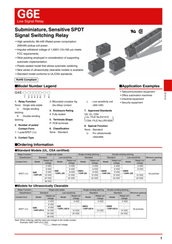
G6ELow Signal RelaySubminiature, Sensitive SPDTSignal Switching Relay High sensitivity: 98-mW (Rated power consumption:200mW) pickup coil power. Impulse withstand voltage of 1,500V (10 160 μs) meetsFCC requirements. Stick packing employed in consideration of supportingautomatic implementation. Plastic-sealed model that allows automatic soldering. New series of ultrasonically cleanable models is available. Standard model conforms to UL/CSA standards.RoHS Compliant Model Number Legend Application Examples G6E-@ -@ @@ @ @ -@ -@— ————— — —12 3 4 5 6781. Relay FunctionNone : Single-side stableU : Single-windinglatchingK : Double-windinglatching3: Bifurcated crossbar Ag(Au-Alloy) contactL4. Enclosure Rating4: Fully sealed7. Approved StandardsUS: UL, CSAUL: FILE No.E41515CSA: FILE No.LR31928(5. Terminals ShapeP: PCB terminals2. Number of poles/Contact Form1: 1-pole/SPDT (1c): Low sensitivity coil(400 mW)Telecommunication equipmentOffice automation machinesIndustrial equipmentSecurity equipmentG6E)8. Special FunctionNone : StandardU : For ultrasonicallycleanable6. ClassificationNone : Standard3. Contact Type Ordering Information Standard Models (UL, CSA certified)Relay FunctionClassificationContact formSPDT (1c)Single-side stableStandardModelRated coilvoltageG6E-134P-USSingle-winding latchingLow-sensitivityRated coilvoltageModelDouble-winding latchingStandardStandardRated coilvoltageModelLow-sensitivityRated coilvoltageModel5 VDC5 VDC5 VDC5 VDC6 VDC6 VDC6 VDC6 VDC9 VDC12 VDCG6E-134PL-US24 VDC48 VDCG6EU-134P-US9 VDC12 VDC12 VDC24 VDC G6EK-134P-US9 VDC ModelG6EK-134PL-US12 VDC24 VDC Minimum packingunit5 VDC9 VDC24 VDC Rated coilvoltage6 VDC 12 VDC25 pcs/tube24 VDC Models for Ultrasonically CleanableRelay FunctionClassificationContact formSingle-side stableStandardModelRated coilvoltageModel5 VDC6 VDCSPDT (1c)G6E-134P-US-USingle-winding latchingDouble-winding latchingStandardStandardLow-sensitivity9 VDC12 VDCModel5 VDCG6E-134PL-US-U24 VDC48 VDCRated coilvoltage 12 VDC Model5 VDCG6EU-134P-US-U 12 VDC Rated coilvoltageMinimum packingunit5 VDCG6EK-134P-US-U 24 VDC Rated coilvoltage 12 VDC25 pcs/tube24 VDC Note: When ordering, add the rated coil voltage to the model number.Example: G6E-134P-US 5 VDCRated coil voltage1
G6ELow Signal Relay Ratings Coil: Single-side StableClassificationRated voltageRatedcurrent(mA)5 VDC40.01256 VDC33.31809 VDC22.240512 VDC16.772024 VDC8.32,88048 VDC8.35,760StandardCoilresistance(Ω)5 VDC79.4636 VDC66.6909 VDC44.320312 VDC33.336024 VDC16.71,440Low-sensitivityMust operate Must releasevoltagevoltage(V)(V)Max.voltage(V)% of rated voltage70% max.10% min.70% max.10% min.Powerconsumption(mW)190%(at 23 C)Approx. 200170%(at 23 C)Approx. 400170%(at 23 C)Approx. 400 Coil: Single-winding latchingContact typeG6ERated voltageRated current(mA)5 VDC40.01256 VDC33.31809 VDC22.240512 VDC16.772024 VDC8.32,880BifurcatedcrossbarMust set voltage Must reset voltage(V)(V)Coil resistance(Ω)Max. voltage(V)% of rated voltage70% max.70% max.190%(at 23 C)Power consumptionSet coil (mW)Reset coil (mW)Approx. 200Approx. 200 Coil: Double-winding latchingRated current (mA)ClassificationCoil resistance (Ω)Rated voltageSet coilReset coil5 VDC40.040.01251256 VDC33.333.31801809 VDC22.222.240540512 VDC16.716.7720720StandardSet coilReset coil24 VDC8.38.32,8802,8805 VDC79.479.463636 VDC66.666.690909 VDC44.344.320320312 VDC33.333.336036024 VDC16.716.71,4401,440Low-sensitivityMust setvoltage(V)Must resetvoltage(V)% of rated voltageLoadItemContact typeBifurcated crossbarContact materialRated loadRated carry currentInductive load(cosφ 0.4; L/R 7 ms)Resistive loadAg (Au-Alloy)0.4 A at 125 VAC;2 A at 30 VDC0.2 A at 125 VAC;1 A at 30 VDC3AMax. switching voltage250 VAC, 220 VDCMax. switching current3A2Power consumptionSet coil(mW)Reset coil(mW)70% max.70% max.190%(at 23 C)Approx. 200Approx. 20070% max.70% max.170%(at 23 C)Approx. 400Approx. 400Note 1. The rated current and coil resistance are measured at a coil temperature of 23 C with a tolerance of 10%.2. Operating characteristics are measured at a coil temperature of 23 C.3. The maximum voltage is the highest voltage that can be imposed on the relay coil.4. Refer to the engineering data for relations between the ambient temperature and maximum coil voltage. ContactsMax.voltage(V)
G6ELow Signal Relay Characteristics (Including Models for Ultrasonically Cleanable)ItemRelay FunctionContact resistance *1Operate (set) timeRelease (reset) timeMin. set pulse widthMin. reset pulse widthInsulation resistance *2Impulse withstand Between coil and contactsvoltageBetween contacts of same polarityBetween coil and contactsDielectric strengthBetween contacts of same estructionShock de StableSingle-winding Latching50 mΩ max.5 ms max.5 ms max. Double-winding Latching15 ms15 ms1,000 MΩ min. (at 500 VDC)2,500 V (10 160 μs) (conforms to FCC part 68)1,500 V (10 160 μs) (conforms to FCC part 68)1,500 VAC, 50/60 Hz for 1 min1,000 VAC, 50/60 Hz for 1 min10 to 55 to 10 Hz, 2.5 mm single amplitude (5 mm double amplitude)10 to 55 to 10 Hz, 1.65 mm single amplitude (3.3 mm double amplitude)1,000 m/s2300 m/s2100,000,000 operations min. (at 36,000 operations/hr)100,000 operations min. (0.4 A at 125 VAC resistive load; 0.2 A at 125 VAC inductive load)(at 1,800 operations/hr)500,000 operations min. (2 A at 30 VDC resistive load; 1 A at 30 VDC inductive load)(at 1,800 operations/hr)200,000 operations min. (3 A at 30 VDC resistive load) (at 1,800 operations/hr)10 μA at 10 mVDC-40 C to 70 C (with no icing or condenstion)5% to 85%Approx. 2.7 gElectricalFailure rate (P level) (reference value) *3Ambient operating temperatureAmbient operating humidityWeightNote: The values here are initial values.*1. The contact resistance was measured with 1 A at 5 VDC using a voltage-drop method.*2. The insulation resistance was measured with a 500 VDC Megger Tester applied to the same parts as those used for checking the dielectric strength.*3. This value was measured at a switching frequency of 120 operations/min and the criterion of contact resistance is 50 Ω.This value may vary depending on the switching frequency and operating environment. Always double-check relay suitability under actual operating conditions. Engineering Data5DC resistive load32AC resistive load1DC inductive load(L/R 7 ms)0.50.40.30.2AC inductive load(cosφ 0.4)0.050.03351010,0005,0003,00030 VDC inductive load(L/R 7 ms)1,00050030 VDC resistive load30020 30 50 20018050 0.2 0.4300 500 1,0001G6E-134PL-USG6EK-134PL-USG6EU-134P-USOnly at 48VDC160100 125 VACresistive50load30125 VACinductive load10(cosφ 0.4)0.10.010 Ambient Temperature vs.Maximum Coil VoltageMaximum coil voltage (%)10 DurabilityDurability (x104 operations)Switching current (A) Maximum Switching Power1401201002340-50-40-20020Switching current (A)Switching voltage (V)406080 100Ambient temperature ( C)Note: The maximum coil voltage refers to themaximum value in a varying range ofoperating power voltage, not a continuousvoltage. Shock MalfunctionG6E-134P-US100De-energizedCoil is applied with130% of rated 4020Coil is applied with100% of rated voltageHot start voltage(max. value)Cold start voltage(max. value)Release voltage athot start (min. value)Release voltage atcold start (min. value)50006001,000Z'X'1,0001,0000-40Voltage not applied to the coil and contacts-20020406080100 120Shock directionXX'YZZ'Y'Y'Unit: m/s2Sample: G6E-134P-US 24 VDCNumber of Relays: 10 pcsZ1,00060007001,000Z'1,000Y'Unit: m/s2Sample: G6EK-134P-US 12 VDCNumber of Relays: 20 pcsShock directionXX'YZZ'Y'X'1,000Coil terminalVoltage not applied tothe coil and contactsX1,000Z1,000Contact terminal60X1,000Coil terminalCoil is applied with100% of rated voltageContact terminalOn the basis of rated voltage (%) Ambient Temperature vs. MustOperate or Must Release VoltageAmbient temperature ( C)Test Conditions: Shock is applied in X, Y, and Z directions three times each with and without energizing theRelays to check the number of contact malfunction.3G6E
G6ELow Signal Relay Contact Reliability Test (70 C) *1, *2G6E-134P-US605040Must30 releasevoltage20min.Sample: G6E-134P-US 24 VDCNumber of Relays: 10 pcsTest conditions: Resistive load at10 VDC 0.01 mASwitching frequency: 1,800 operations/hmax.min.10Contact resistance (mΩ)1007050NO contact NC contactmax.30min.min.1030 50100300 500 1,0003,000 5,000Operating frequency ( 104 operations)G6E0Sample: G6E-134PNumber of Relays: 5 pcsNC contact202.54 mm60min.505.08 mm40max.30 Must release voltageRelays otherthan thetestingmodels arede-energized20min.Sample: G6E-134P-US 24 VDCNumber of Relays: 10 pcsTest conditions: Resistive load at 5 VDC 1 mASwitching frequency: 120operations/minNO contact NC contactmax.10305.08 mmmin.100.10.3 0.5 13 51030 50 100300 500Rotation ( 104 turns) High-frequency Characteristics(Insertion Loss) *1, *3(Average value (initial))G6E-134P-USInsertion loss (dB)Isolation (dB) High-frequency Characteristics(Isolation) *1, *3(Average value (initial))G6E-134P-USmax.70 Must operate voltage1007050max.Must operate voltageMust release voltage80Relays otherthan thetestingmodels arede-energizedChange rate on thebasis of initial value (%)max. Mutual Magnetic InterferenceG6E-134P-US2.54 mmChange rate on thebasis of initial value (%)70 Must operate voltageContact resistance (mΩ)On the basis of rated voltage (%)80On the basis of rated voltage (%) Contact Reliability Test *1, *2G6E-134P-USInitial stageTest2.01.00 1.0 2.0Average valueInitial stageTest2.01.00 1.0 2.0Average value0Sample: G6E-134PNumber of Relays: 5 pcsNC contact1402NO contactNO contact60380110100411,0001010050Sample: G6E-134P-USNumber of Relays: 100 pcsTest conditions: 100% of40 coil voltage appliedMust operate timeMust release timeG6E-134PL-USNumber of contactsNumber of contacts Must Operate and Must ReleaseTime Distribution *1G6E-134P-USG6E-134P-US 48 VDC100Sample: G6E-134PL-USNumber of Relays: 100 pcsTest conditions: 100% of80 coil voltage appliedMust operate timeMust release time100Sample: G6E-134P-US48 VDCNumber of Relays: 100 pcs40 Test conditions: 100% ofcoil voltage applied603020402010201001.0 1.2 1.4 1.6 1.8 2.1 2.2 2.4 2.6 2.8 3.0 3.2 3.4 3.61234 Distribution of Bounce Time *1G6E-134P-USRelease bounce timeNumber of contactsOperating bounce time2010100.3Time (ms)0.4Time (ms)Release bounce time*1.*2.200.21.0 1.2 1.4 1.6 1.8 2.0 2.2 2.4 2.6 2.8 3.0Operating bounce timeSample:G6E-134PL-US12 VDC40 Number of Relays:50 pcs300.1Must release time503000Must operate timeG6E-134PL-US50Sample:G6E-134P-US12 VDC40 Number of Relays:50 pcs5Time (ms)Time (ms)Number of contacts5030041,000Frequency (MHz)Frequency (MHz)Number of contacts1000*3.0.30.60.91.21.51.82.1Time (ms)The tests were conducted at an ambienttemperature of 23 C.The contact resistance data are periodicallymeasured reference values and are notvalues from each monitoring operation.Contact resistance values will varyaccording to the switching frequency andoperating environment, so be sure to checkoperation under the actual operatingconditions before use.High-frequency characteristics depend onthe PCB to which the Relay is mounted.Always check these characteristics,including durability, in the actual machinebefore use.
G6ELow Signal Relay DimensionsSingle-side L-US-UTerminal Arrangement/Internal Connections(Bottom View)PCB Mounting Holes(Bottom View)Tolerance: 0.116max.(15.9)*Five, 1.0 dia. le-winding 16max.(15.9)** Average value(1.65)5.087.62Five, 1.0 dia. holes(1.19)2.547.620.255.087.627.62* Average value 1? S1210R 6 7Note: Be sure to confirmcoil polarity.3.50.67Note: Orientation marks are indicated as follows:8max.0.3 (7.9)*1.610Note: Be sure to confirmcoil polarity.2.5410max.(9.9)* 61 8max.0.3 (7.9)*(1.65)5.087.62Note: Orientation marks are indicated as follows:G6EDouble-winding ax.(15.9)*Six, 1.0 dia. holes2.5410max.(9.9)*(1.19)2.548max.0.3 (7.9)*7.623.50.61.60.255.087.627.62* Average value(1.65)5.087.62 1S 3? R6 12 107Note: Be sure to confirm coilpolarity. The modelG6EK-134P-1-US has positive( ) terminal #3 and negative(-) terminals #1 and #6.Note: Orientation marks are indicated as follows:5
G6ELow Signal Relay Approved Standards The approval rating values for overseas standards are different from the performance values determined individually. Confirm thevalues before use.UL recognized:CSA certified:(File No. E41515)(File No. LR31928)ContactCoil ratingsformModelG6E( )-134P( )USSPDT(1c)3 to 48VDCContact ratingsNumber of testoperations0.2 A, 250 VAC at 40 C0.6 A, 125 VAC at 40 C2 A, 30 VDC at 40 C0.6 A, 125 VDC at 40 C6,000 Precautions Please refer to “PCB Relays Common Precautions” for correct use.Correct UseG6E Long-term Continuously ONContacts Using the Relay in a circuit where theRelay will be ON continuously for longperiods (without switching) can lead tounstable contacts because the heatgenerated by the coil itself will affectthe insulation, causing a film todevelop on the contact surfaces. Werecommend using a latching relay(magnetic-holding relay) in this kind ofcircuit. If a single-side stable modelmust be used in this kind of circuit, werecommend using a fail-safe circuitdesign that provides protection againstcontact failure or coil burnout. Mounting Do not reverse the polarity of the coil( , ). Provide sufficient space betweenRelays when mounting two or more onthe same PCB, as shown in thefollowing diagram. Wiring Refer to the following diagram whenwiring to switch a DC load. Thedifference in polarity applied to thecontacts will affect the endurance ofthe Relay due to the amount of contactmovement. To extend the endurancecharacteristics beyond theperformance ratings, wire the common(pin 7) terminal to the positive ( ) side. 12Load Relay Handling When washing the product aftersoldering the Relay to a PCB, use awater-based solvent or alcohol-basedsolvent, and keep the solventtemperature to less than 40 C. Do notput the Relay in a cold cleaning bathimmediately after soldering.710LoadWiring Diagram Ultrasonic Cleaning Do not use ultrasonic cleaning onstandard relay models. Doing so mayresult in resonance, coil burnout, andcontact adhesion within the Relay. Usea model designed for ultrasoniccleaning if ultrasonic cleaning isrequired.ClosemountingDistance between terminals:2.54 2 (pitch) max. Application examples provided in this document are for reference only. In actual applications, confirm equipment functions and safety before using the product. Consult your OMRON representative before using the product under conditions which are not described in the manual or applying the product to nuclear control systems, railroadsystems, aviation systems, vehicles, combustion systems, medical equipment, amusement machines, safety equipment, and other systems or equipment that may have a seriousinfluence on lives and property if used improperly. Make sure that the ratings and performance characteristics of the product provide a margin of safety for the system orequipment, and be sure to provide the system or equipment with double safety mechanisms.Note: Do not use this document to operate the Unit.OMRON CorporationElectronic and Mechanical Components Company6Contact: www.omron.com/ecbCat. No. K024-E1-070812(0207)(O)
3 G6E Low Signal Relay G 6 E Characteristics (Including Models for Ultrasonically Cleanable) Note: The values here are initial values. *1. The contact resistance was measured with 1 A at 5 VDC using a voltage-drop method. *2. The insulation resistance was measured with a 500 VDC Megger Test er applied to the same parts as those used for checking the dielectric strength.