Transcription
ELECTRONICS COMPONENTSPOWERMODULE
POWER MODULECONTENTSFive Improvements by Power Supply Modules2Switching power supply and power modules3Features of power modules4Explanation of the Outline5List of Products , SPM Series7External Dimensions / Pin assignment , SPM Series8List of Products , EPM Series9External Dimensions / Pin assignment , EPM Series10List of Products , MPM Series11External Dimensions / Pin assignment , MPM Series12List of Products , BPM Series13External Dimensions / Pin assignment , BPM Series14List of Products , CPM series /Constant Current type , LED driver15External Dimensions / Pin assignment , CPM Series16Usage cautions171
POWER MODULEFive Improvements by Power Supply Modules2
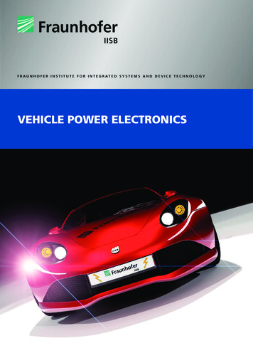
POWER MODULESwitching power supply and power modulesCurrently, a switching power supply is widely used to convert commercial AC power supplied to generalhouseholds (AC 100 V in Japan) into DC power.A switching power supply converts voltage by rapidly flipping a semiconductor switch on and off (about100,000 times per second). As for its features, it offers high conversion efficiency and allows size andweight reduction. It is used in AC adapters for cellphones, smartphones, notebook PCs, etc.Tamura has developed power modules that function as circuits of switching power supply, as described in“Voltage conversion by switching control” within the dotted line in the figure below. The integration of keydevices—transformers, control circuits, and semiconductor switches—into a single package allows easydesign of power supplies with a small number of components.The circuit described within the dottedline is developed as a module.TransformerAC inputDC outputSemiconductorswitchAC 100 V to 240 VDC 3.3 V, etc.ACRectificationVoltage conversion byswitching control3Rectification
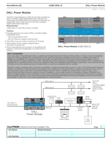
POWER MODULEFeatures of power modulesEasy design of power supplies with high efficiency and low standby power consumption!Tamura’s power modules employ circuit technologies that incorporate know-how of original technologiesTamura has developed to achieve low standby power consumption and high efficiency.This facilitates the design of high-performance power supplies that can significantly reduce standby powerconsumption under no load and maintain high efficiency across the entire load range from low load to ratedload.Significant reduction in man-hours for design and evaluation!You can greatly simplify very important processes in power supply development—transformer design,thermal design, safety standard compliance, open and short circuit testing, and EMS evaluation.It is possible to reduce development man-hours required before mass production of power supplies byabout 80%, thereby reducing development cost and fetyComprehensiveevaluation evaluationMan-hours for development withgeneral-purpose componentsMan-hours for development withmodulesReduction by about020406080%80100 ( )%Reduction in mounting areaAs the key components are housed in the modules, mounting area can be reduced to about half of that foran arrangement of general-purpose components.Arrangement ofgeneral-purpose componentsPower moduleArea ratio2 :1(By comparison with Tamura’s discrete products)4
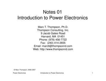
POWER MODULEExplanation of the OutlineWith our original circuit technology, Tamura’s power modules has the capability of design resourcereduction, ultra-low standby power consumption and high efficiency.And also have made it possible to have low standby power & high efficiency at low power externalcomponents.Will contribute design time and development cost reduction.Output Current / Output voltage10ASPM7AEPM5AMPMBPMOutput Current3A2ABPM1A0.7AMPMEPM0.5A0.3A0.2ASPM0.1A3.3V 5V12V 15V24V36V48VOutput voltageProduct LineupSeriesSPM SeriesEPM SeriesMPM SeriesBPM SeriesClass4W15W25W40WProduct5
POWER MODULEExplanation of the OutlineOutlineTamura’s power module s are energy-saving switching power supply modules with switching transformer,IC control, circuit control and a built-in (FET) switching component.By attaching an external input noise filter, input rectifier diode, output smoothing capacitor ahigh-efficiency and high performance switching power supply with low standby power can easily becreated with the EPM.DC INDC OUTDiodeInternal parts and functionsInsulation TransformerIsolated Transformer ControlICPhoto-couplerOTPIC controlOutput rectifier diodePhoto-couplerOutput voltage detection circuitPrimary side control circuitOver voltage protectionOver current protectionHeating protection circuitSwitchingPowerSupply canbe easilycreatedPowerModuleApplicationsIndustrial equipment, Information processing equipment, AV equipment, Consumer electronics, Standbypower, Small power, etc.FeaturesCapable of high efficiency from quasi resonant operationLow standby power consumption because of the combination of behavior and burst frequency reductionCorresponding world wide input and PFC output voltage (Vin:DC110V 450V)Reinforced insulation between primary and secondary (AC3000V 1 minute gurantee)Capable of low noise for Tamura’s unique structureCorrespondence of various safety standard (Information equipment, AV equipment, Industrial equipment,Home appliance)Various built-in protection function (Over-current protection, Over-voltage protection, Overheatprotection)6
POWER MODULEList of Products , SPM SeriesSPM JSPM2402SJRated Output Voltage / Rated Load3.3V / 0.7A5V / 0.66A12V / 0.28A15V / 0.22A24V / 0.14AOutput voltage tolerance (10 100% Load) 10% 7.5% 6% 5% / -6%Output voltage tolerance (0 10% Load) 15% / -10% 12% / -10% 10% 10%Input Voltage RangeDC110 - 390VEfficiency (DC140V, Rated load, Ta 25 C)70%(typ)76%(typ)80%(typ)82%(typ)No-load power (DC140V, Ta 25 -p150mVp-p250mVp-p400mVp-pRipple & Noise200mVp-p200mVp-p300mVp-p500mVp-pUnder developmentItemDC110 - 420VOver Current ProtectionAuto recoveryOver Temperature ProtectionAuto recoveryProtectionInsulation VoltageAC3000V 1min Cut off current 2mAInsulationInsulation ResistanceDC500V 100M1minAmbient Temperature (Operating)-20 95 C ( 75 95 C : stand for derating)Ambient Humidity (Operating)20 95%RH (Nil condensation)Ambient Temperature (Storage)-25 100 CAmbient Humidity (Storage)5 95%RH (Nil condensation)Vibration10 55Hz 49.0m/s2 3min cycle X,Y,Z direction each onceShock196.1m/s2 11ms X,Y,Z direction each onceEnvironment7
POWER MODULEExternal Dimensions / Pin assignmentExternal DimensionsPin assignmentPrimary sideSecondary sidePin No.NameDescriptionPin No.NameDescription1Vin(-)Input (-)6N.C.N.C.(unable to connect to other circuits)2-No pin7N.C.N.C.(unable to connect to other circuits)3DrainNoise adjustment8W1Secondary winding terminal4-No pin9VoOutput ( )5Vin( )Input (-)10GNDOutput (-)8
POWER MODULEList of Products , EPM SeriesEPM SeriesRoHSModelItemRated Output Voltage / Rated LoadEPM0310SJ EPM0510SJEPM1205SJEPM1210SJ EPM1505SJ EPM1510SJ EPM2405SJ3.3V / 1.0A12V / 0.5A12V / 1.0A5V / 1.0AOutput voltage tolerance 5%Input Voltage RangeDC110 - 450V15V / 0.5A15V / 1.0A24V / 0.5AEfficiency (DC140V, Rated load, Ta 25 90%(typ)No-load power (DC140V, Ta 25 W(typ)28mW(typ)Line Regulation50mV50mV50mV100mV100mV100mV100mVLoad e60mV60mV120mV120mV150mV150mV240mVRipple & Over Current ProtectionAuto recoveryOver Voltage ProtectionLutch offOver Temperature ProtectionLutch offInsulation VoltageAC3000V 1min Cut off current 2mAInsulation ResistanceDC500V 100M1minAmbient Temperature (Operating)-20 80 C ( 60 80 C : stand for derating)Ambient Humidity (Operating)20 95%RH (Nil condensation)Ambient Temperature (Storage)-25 85 CAmbient Humidity (Storage)5 95%RH (Nil condensation)Vibration10 55Hz 49.0m/s2 3min cycle X,Y,Z direction each onceShock196.1m/s2 11ms X,Y,Z direction each onceInsulationEnvironment9
POWER MODULEExternal Dimensions / Pin assignmentExternal DimensionsEF19S, EF19DEF22S, EF22DFE19S 1 3 : With no pinFE22S 1 3 : With no pinPin assignmentFE19S, FE22SPrimary sideSecondary sidePin No.NameDescriptionPin No.NameDescription8FBN.C.(unable to connect to other circuits)1-No pin2-No pin9VccWN.C.(unable to connect to other circuits)10-DCINInput (-)3-No pin11VccStart-up time adjustment4SecWN.C.(unable to connect to other circuits)12 DCINInput ( )5 DCOUTOutput ( )13-No pin6N.C.N.C.(unable to connect to other circuits)14DrainNoise adjustment7-DCOUTOutput (-)DescriptionPin No.NameDescriptionFE19D, FE22DPrimary sidePin No.NameSecondary side8FBN.C.(unable to connect to other circuits)1SecW2-1N.C.(unable to connect to other circuits)9VccWN.C.(unable to connect to other circuits)2 DCOUT2Output2 ( )10-DCINInput (-)3SecW2-211VccStart-up time adjustment4SecW12 DCINInput ( )5 DCOUTOutput1 ( )Relay ( 3 - 4 pin short)13-No pin6AdjustOutput voltagea adjustment14DrainNoise adjustment7-DCOUTOutput (-)10
POWER MODULEList of Products , MPM SeriesMPM SeriesRoHSModelItemRated Output Voltage / Rated PM4806SJ5V / 2.7A12V / 2.0A15V / 1.7A24V / 1.1A36V / 0.75A48V / 0.58AOutput voltage tolerance 5%Input Voltage RangeDC100 〜 420VEfficiency ( DC140V, Rated load, Ta 25 C)T.B.D86% ( TYP)T.B.DT.B.D90% ( TYP)T.B.DNo-load power ( DC140V, Ta 25 C)50mW or less50mW or less50mW or less50mW or less75mW or less75mW or lessLine RegulationT.B.D100mVT.B.DT.B.D100mVT.B.DLoad 80mV300mV430mV570mVProtectionOver Current ProtectionAuto recoveryOver Voltage ProtectionLutch offOver TemperatureProtectionLutch offInsulation VoltageAC3000V 1min Cut off current 2mAInsulation ResistanceDC500V 100M1minAmbient Temperature( Operating ) 20 〜 80 ( 50 〜 80 : stand for derating )Ambient Humidity( Operating )20 〜 95% RH ( Nil condensation )Ambient Temperature( Storage ) 25 〜 85 Ambient Humidity( Storage )5 〜 95% RH ( Nil condensation )Vibration10 〜 55Hz 49.0m/s2 3min cycle X,Y,Z direction each onceShock196.1m/s2 11ms X,Y,Z direction each onceInsulationEnvironment*While it's development, without announcing beforehand, so there is a case that the specification changes.11
POWER MODULEExternal Dimensions / Pin assignmentExternal DimensionsPin assignmentPrimary sideSecondary sidePin No.NameDescriptionPin No.NameDescription1Vin( )DC volt input terminal ( )7REFOutput voltage adjustment terminal2DrainTerminal for noise adjustment8RC(-)Output voltage detection terminal (-)3Vin(-)DC volt input terminal (-)9GNDOutput terminal (-)4VccTerminal for start-up time adjustment10GNDOutput terminal (-)5VccWN.C. (Unable to connect to other circuits)11GNDOutput terminal (-)6N.C.N.C. (Unable to connect to other circuits)12VoOutput1 terminal (-)1213VoOutput1 terminal ( )14RC( )Output voltage detection terminal ( )
POWER MODULEList of Products , BPM SeriesBPM JBPM2417SJRated Output Voltage / Rated Load3.3V / 9.0A5V / 8.0A12V / 3.4A15V / 2.7A24V / 1.7AOutput voltage toleranceUnder develoopmentItemInput Voltage RangeEfficiency (DC140V, Rated load, Ta 25 C)No-load power (DC140V, Ta 25 C)Line RegulationLoad RegulationRippleRipple & NoiseProtection 5%DC100 Over Current ProtectionAuto recoveryOver Voltage ProtectionLutch offOver Temperature ProtectionLutch offInsulation VoltageAC3000V 1min Cut off current 2mAInsulation ResistanceDC500V 100M1minAmbient Temperature (Operating)-20 80 C ( 50 80 C : stand for derating)Ambient Humidity (Operating)20 95%RH (Nil condensation)Ambient Temperature (Storage)-25 85 CAmbient Humidity (Storage)5 95%RH (Nil condensation)Vibration10 55Hz 49.0m/s2 3min cycle X,Y,Z direction each onceShock196.1m/s2 11ms X,Y,Z direction each onceInsulationEnvironment13
POWER MODULEExternal Dimensions / Pin assignmentExternal DimensionsPin assignmentPrimary sideSecondary sidePin No.NameDescriptionPin No.NameDescription1Vin( )Input ( )7REFOutput adjustment2DrainNoise adjustment8RC(-)Output detection (-)3Vin(-)Input (-)9GNDOutput (GMD)4VccStart-up time adjustment10GNDOutput (GMD)5VccWControl pin11GNDOutput (GMD)6N.C.N.C.(unable to connect to other circuits)12Vout( )Output ( )13Vout( )Output ( )14RC( )Output detection ( )14
POWER MODULEList of Products , CPM series / Constant Current type , LED driverCPM SeriesRoHSVin( )OUT( )CPM ModuleVin(-)OUT(-)Output current setting pinDimming signal (PWM or linea)Dimming signal input pinModelItemCPM3417RAInputVoltage rangeMax loadpowerVoltage rangeCPM6018RAAC90 - 264V / 47 - 63Hz17W max18W maxDC17V-34VDC30V-60V* It's restricted by the current set value.* It's restricted by the current set value.OutputCurrentsetting range0.3A-0.38A0.4A-0.5A* Externally adjusted by connecting resistorsCurrentaccuracy* Externally adjusted by connecting resistors 10%84%typ86%typEfficiency* At the rated input voltage and 17W outputpower and at Ta 25ºCPower factor* At the rated input voltage and 17W outputpower and at Ta 25ºC* At the rated input voltage and 18W outputpower and at Ta 25ºC85% or more85% or more* At the rated input voltage and 18W outputpower and at Ta 25ºC5 - 100%Dimming range* PWM:1kHz 0 - 5VLINEAR:0.74V - 2.45V at Ta 25ºCOutput short-circuit protectionAutomatic recoveryOvervoltage protectionAutomatic recoveryOverheat protectionAutomatic recoveryInsulation voltageAC 3000V/1 minute (cut-off current 2mA)Operating temperature range 20ºC to 70ºC* Derated depending on the load conditionsOperating humidity range20% to 95% RH (There must be no condensation)15
POWER MODULEExternal Dimensions / Pin assignmentExternal DimensionsPin assignmentPrimary sidePin No.NameSecondary sideDescriptionPin No.NameDescription1OVP(A)OVP detection terminal (A)3-No terminal2OVP(K)OVP detection terminal (K)4-No terminal8DIMDimming signal input terminal5Io(-)Output terminal (-)9VccWN.C. (Unable to connect to other circuits)6Io( )Output terminal ( )10Vin(-)Input terminal (-)7SecWN.C. (Unable to connect to other circuits)11IsetConstant current setting terminal12Vin( )Input terminal ( )13-No pin14DrainN.C. (Unable to connect to other circuits)16
POWER MODULEImportant notice The content of this manual is subject to change without prior notice for the purpose of improvements,etc. Ensure that you are in possession of the most up-to-date information when using this product. The operation examples and circuit examples shown in this manual are for reference purposes only, andTamura Corporation disclaims all responsibility for any violations of industrial property rights, intellectualproperty rights and any other rights owned by Tamura Corporation or third parties that these may entail. The circuit examples and part constants listed in these specifications are provided as reference forthe verification of characteristics. You are to perform design, verification, and judgment at your ownresponsibility, taking into account the various conditions. TAMURA Corporation constantly strives to improve quality and reliability, but malfunction or failures arebound to occur with some probability in power products. To ensure that failures do not cause accidentsresulting in injury or death, fire accidents, social damage, and so on, you are to thoroughly verify thesafety of their designs in devices and/or systems. This product is intended for use in consumer electronics (electric home appliances, business equipment,information equipment, communication terminal equipment, measuring devices, and so on.) Ifconsidering use of this product in equipment or devices that require high reliability (medical devices,transportation equipment, traffic signal control equipment, fire and crime prevention equipment,aeronautics and space devices, nuclear power control, fuel control, in-vehicle equipment, safety devices,and so on), please consult a TAMURA sales representative in advance. Do not use this product for suchapplications without written permission from TAMURA Corporation. This product is intended for use in environments where consumer electronics are commonly used. It isnot designed for use in special environments such as listed below, and if such use is considered, you areto perform thorough safety and reliability checks at your own responsibility.・Use in liquids such as water, oil, chemical solutions, or organic solvents, and use in locations wherethe product will be exposed to such liquids・Use that involves exposure to direct sunlight, outdoor exposure, or dusty conditions・Use in locations where corrosive gases such as salt air, C12, H2S, NH3, SO2, or NO2, are present・Use in environments with strong static electricity or electromagnetic radiation・Use that involves placing inflammable material next to the product・Use of this product either sealed with a resin filling or coated with resin・Use of water or a water soluble detergent for flux cleaning・Use in locations where condensation is liable to occur This product is not designed to resist radiation. This product is not designed to be connected in series or parallel. Do no operate this product in a series,parallel, or N 1 redundant configuration. The content of this manual may not be transferred or copied without prior written permission.17
POWER MODULEImportant notice Do not use or otherwise make available the TAMURA products or the technology described in thisdocument for any military purposes, including without limitation, for the design, development, use,stockpiling or manufacturing of mass destruction weapons (e.g. nuclear, chemical, or biologicalweapons or missile technology products). When exporting and re-exporting the products or technologydescribed in this document, you should comply with the applicable export control laws and regulationsand follow the procedures required by such laws and regulations including, without limitation, Japan-Foreign Exchange and Foreign Trade Control Law and U.S.- Export Administration Regulations. TheTAMURA products and related technology should not be used for or incorporated into any products orsystems whose manufacture, use, or sale is prohibited under any applicable domestic or foreign laws orregulations. Please contact your TAMURA sales office for details as to environmental matters such as the RoHScompatibility of Product. Please use TAMURA products in compliance with all applicable laws andregulations that regulate the inclusion or use of controlled substances, including without limitation, theEU RoHS Directive.TAMURA assumes no liability for damages or losses occurring as a result of your noncompliance withapplicable laws and regulations. TAMURA assumes no liability for damages or losses incurred by you or third parties as a result ofunauthorized use of TAMURA products. This document and any information herein may not be reproduced in whole or in part without priorwritten permission from TAMURA.18
HEAD OFFICE1-19-43, Higashi-Oizumi, Nerima-ku, Tokyo, 178-8511 JapanSAKADO OFFICE5-5-30 Chiyoda Sakado-shi Saitama 350-0214 JapanTel : 049-284-5711 Fax : 049-284-5715OSAKA SALES OFFICEEsaka-Sanshoubill 3-27-27 Tarumi-cho Suita-shi Osaka 564-0062 JapanTel : 06-6380-2300 Fax : 06-6385-8371NAGOYA SALES OFFICE3-1803, Kamiyashiro, Meito-ku, Nagoya-shi, Aichi, 465-0025 JapanTel : 052-701-1210 Fax : 052-701-1295TAMURA CORPORATION OF CHINA LIMITED13F, Block A, International Shopping Centre Shanghai No.527Huaihai Zhong Road, Shanghai, ChinaTel : 86-21-6387-9388 Fax : 86-21-6387-9268TAMURA ELECTRONICS(S.Z.)CO.,LTD.3014, Ban Xue Gang Street, Ban Tian Community,Ban Tian Subdistrict, Long Gang District,Shen Zhen City, ChinaTel : 86-755-8950-2603 Fax : 86-755-8950-2325TAMURA CORPORATION OF KOREA#514, Hyundai I-Valley 223-12, Sangdaewon 1-dong, Jungwon-gu,Seongnam-si, Gyeonggi-do, 462-714, KoreaTel : 82-2-489-5354 Fax : 82-2-489-5360TAMURA ELECTRONICS(M)SDN.BHD.Lot No.1, Jalan SS 8/6, Sungai Way Free Industrial Zone,47300 Petaling Jaya, Selangor, MalaysiaTel : 60-3-7680-9000 Fax : 60-3-7876-3300TAMURA CORPORATION OF AMERICA1040 South Andreasen Drive, Ste.100 Escondido, CA 92029 U.S.A.Tel : 1-951-699-1270 Fax : 1-951-676-9482TAMURA EUROPE LIMITED.Clark Avenue Porte Marsh Industrial Estate Calne WiltshireSN11 9BS United KingdomTEL : 44(0)-1380-731-700 FAX : 44(0)-1380-731-7032016.9.TR
As the key components are housed in the modules, mounting area can be reduced to about half of that for an arrangement of general-purpose components. Reduction in mounting area Arrangement of general-purpose components Power module (By comparison with