Transcription
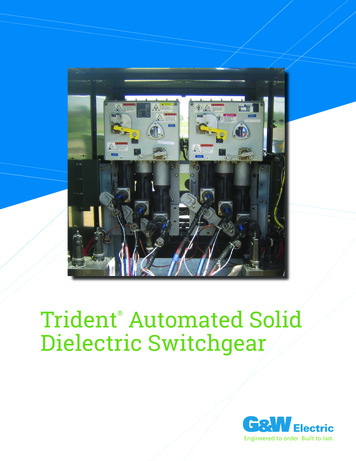
Trident Automated SolidDielectric Switchgear
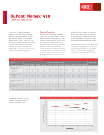
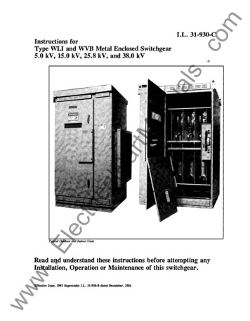
When you need visible break.Trust Trident with SafeVu Trident-SR w/ SafeVu and Trident-SR Switch SeriesUtilizing the same magnetic actuator technology as G&W Electric’sViper reclosers, the Trident-SR series switches offer extremely fastoperation speeds of just 3.5 cycles for both load and fault interruptingoperations. Its flexible design can be configured to provide a wide range ofsolutions for any application, from basic remote operation, to distributionautomation, or Smart Grid schemes. Trident-SR switches offer multipleapplication functionality within a same compact switch footprint.SafeVu Visible BreakThe load break and fault interrupter ways are available with G&W’s SafeVufeature, which provides an integrated visible break disconnect switch inseries with the vacuum interrupter. This eliminates the need to removeelbows or use externally mounted linkage systems to provide a visibleopen. Switches equipped with SafeVu incorporate redundant mechanicalinterlocks to ensure the vacuum bottle is open prior to the operation of thevisible break switch.Trident-SR w/ SafeVuAvailable up to 15.5kVIntegral visible breakin the open position.Internal components are shownoutside the model as reference.Automation FlexibilityThe Trident-SR switch series was specifically designed to provide the highspeed switching required for distribution automation schemes. Switchconfigurations can be paired with various control packages to provide thefeatures required for a wide variety of applications including AutomaticTransfer in under 10 cycles.Trident-SR Trident Automated Solid Dielectric Switchgear
Ratings for TridentThe switch is designed, tested and built per IEEE C37.74 for load break switching, IEEE C37.60 for fault interrupting,IEEE 386 for bushing specification, and IEC 60529 for environmental protection rating. Padmount switch enclosuresare designed per C57.12.28 or C57.12.29. Certified test reports are available upon request.Voltage Class (kV)152535Max. System Voltage (kV)15.527‡38BIL (kV) 110Δ 125 150110Δ125150Continuous Current (A)630§630§630§Load Break Current (A)630§630§630§AC Withstand, 1 min. (kV)356070AC Withstand, Productions, 1 min.(kV)344050DC Withstand, 15 min.5378103Momentary Current, RMS, asym (kA)202020Fault Close 3 times, asym (kA)2020201 second Current, sym (kA)12.512.512.5Fault Interrupting Current, sym (kA)12.512.512.510,00010,00010,000Vacuum Interrupter MechanicalOperationsNote:Δ BIL impulse rating is 95kV when using the SafeVu feature‡ Up to 29.3kV Max. System Voltage available§ Up to 900A available on In/Out without SafeVu, Up to 800A available on multiway Trident without SafeVuComponentsOvercurrent ProtectionFault interrupters with SafeVu are equipped with an encapsulated 500:1 or 1000:1 current transformers and faultinterrupters without SafeVu are equipped with an encapsulated 200:1 or 400:1 current transformers A wide variety ofprotective relay packages are available, including relays from SEL and other leading relay suppliers.External CTs and External PTsMetering or relaying accuracy current and potential transformers are available for use with protective relaypackages.Operating HandleG&W will select the appropriate handle based on the application. Handles are operable via hook stick or rope rigging.Key InterlocksKey interlocks may be used to ensure safe coordination of equipment. All Trident ways can be equipped with provisionsfor key interlocks. Key interlocks can be provided, and factory installed if required.Auxiliary ContactsAuxiliary contacts are internally mounted to the mechanism housing providing remote indication of switch contactposition. One normally open and one normally closed Form C contact is provided. A junction box is available withterminal strip connections for up to three auxiliary contacts.
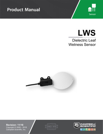
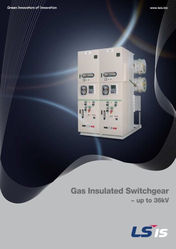
Voltage SensingG&W’s Voltage Sensing (VS) Bushings are available in Dead Break Apparatus or 200A Deepwell. The VS istemperature compensated, built-in, voltage measuring system that eliminates the need for PTs in analogphase to ground voltage monitoring. Compared to potential transformers, the VS bushing system offersthese benefits: Significant cost savingsCleaner, less cumbersome installationLess space requiredFewer add-on components which could potentially failInstalled and tested prior to shipmentOutput0-8VAC0-120VACTemperatureAccuracy-20 C (-4 F) to 40 C (104 F) /- 2%-60 C (-76 F) to 65 C (149 F) /- 4%-60 C (-76 F) to 65 C (149 F) /- 5%Voltage sensors are available as LEA (Low Energy Analog) or 120VAC output. Capacitive voltage sensorsencapsulated within the bushings permit voltage reading for network reconfiguration while eliminating theneed for add-on sensors and cabling. The phase angle accuracy is /-1 throughout the full temperaturerange.ControlsEach G&W automated switch comes equipped with a pre-installed integralcontrol package. Each control package is built on the platform of SELhardware, and is pre-programmed and configured to provide the followingfunctionality: Local/Remote Actuator ControlAnalog Current Monitoring for all waysAnalog Voltage Monitoring for two waysOvercurrent Protection for all Fault InterruptersRemote Position Status Indication for all waysEach control package is equipped with an integral power supply and optionalbattery back-up with automated battery test feature. Each control alsocomes standard with a DNP point map to controls and monitor the switchusing SCADA. Ethernet or fiber optic ports for communications are available.ATC PackagesControl located on automated TridentUsing either an SEL451-5 or SEL751 relay, G&W can supply a control that provides auto-transfer betweentwo sources. Controls are available for common-bus and bustle configurations with transfer in less than 10cycles.Control OptionsFor padmount and dry vault applications, the control can be supplied in either a mild steel NEMA 4 enclosureor a stainless steel NEMA 4X enclosure. Both of these enclosures can be supplied in a compact size (24”tall by 24” wide) or in a larger size 30” tall by 24” wide)) to accommodate additional equipment such ascommunication devices.The NEMA 4 and NEMA 4X enclosures have several options including a padlocking handle, convenienceoutlet, test switches and a document holder.
Part Number Configuration For Trident-SRCharacter12345Sample PartNumberPMR321. Type of InstallationP Padmount (enclosure)V Vault (no enclosure)2. Type of Load Break SwitchesM Trident-SRL Trident-S*Leave blank if no load break switches.Consult factory for other options orcombinations of options shown on this page.* See Trident Spring-Operated Solid DielectricSwitchgear Brochure (GW11-2019).3. Type of Fault InterrupterR Trident-SRS Trident-S*T Trident-ST (Single Phase Trip capability)*F Trident-S and Trident-ST combination*U Unswitched bushings directly on busLeave blank if fault interrupters or no unswitched bushingsdirectly on bus.Consult factory for other options or combinationsof options shown on this page.* See Trident Spring-Operated Solid DielectricSwitchgear Brochure (GW11-2019).4. Number of WaysEnter a number 2 through 65. Number of Load Break SwitchesEnter a number 2 through 6, up tothe number as Ways.6. Phase3 Three Phase7. Voltage Class (Maximum System Voltage,Ph-Ph)7 15.5kV8 27kV**9 38kV**Consult factory for 29.3kV options.-6783769-12-101112136FAVU-A8. Continuous Current6 630A8 800A9 900AConsult factory for limitations.9. Fault Interrupting / Close into fault rating12 12.5kA sym. for Fault interrupting switches20 20kA asym. for Load Break switches10. Model3 Single Load Break Way4 Single Fault Interrupting Way6 3 Way with 2 Load Break 1 Fault Interrupter7 3 Way with 1 Load Break 2 Fault Interrupter9 4 Way with 2 Load Break 2 Fault Interrupter10 4 Way with 4 Load Break 0 Fault Interrupter11 4 Way with 3 Load Break 1 Fault Interrupter12 4 Way with 1 Load Break 3 Fault Interrupter13 3 Way with 3 Load Break 0 Fault InterrupterXX Digit 4&5 if combination not listed above11. Configuration (Access Style)FA Front Access to Bushings and OperatorsFB Front Access to Bushings and BackAccess to OperatorsConsult factory for additional options.12. SafeVu includedVU SafeVu included*** (available up to 15.5kV)Leave blank if SafeVu not included***Advise factory if not all ways include SafeVu.13. Automated-A Automated
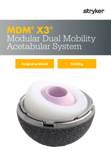
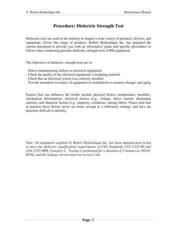
VaultFront Access (FA)Multi-Way TridentPadmountFront Access (FA)PadmountFront/Back Access (FB)# of WaysModelWidthInches (mm)Weightlbs. (kg)WidthInches (mm)Weightlbs. (kg)DepthInches (mm)Weightlbs. (kg)3Non-SafeVu91 (2310)2300 (1000)106 (2700)3200 (1500)77 (1960)3500 (1600)3SafeVu100 (2540)3200 (1500)115 (2700)4100 (1900)92 (2340)3500 (1600)4Non-SafeVu115 (2920)2600 (1200)130 (3300)3500 (1600)77 (1960)3800 (17004SafeVu124 (3150)3500 (1600)145 (3685)4400 (2000)92 (2340)3800 (1700)5Non-SafeVu140 (3560)3100 (1400)155 (3685)3900 (1800)5SafeVu149 (3780)3900 (1800)175 (4445)4700 (2100)6Non-SafeVu165 (4190)3500 (1600)180 (4590)4300 (3000)6SafeVu174 (4420)4300 (2000)200 (5080)5100 (2300)Consult FactoryConsult FactoryTwo-Way Vault (In/Out)ModelDepthInches (mm)WidthInches (mm)HeightInches (mm)Weightlbs. (kg)Non-SafeVu19 (483)22 (559)38 (965)375 (170)SafeVu20 (508)28 (771)40 (1016)375 (170)ModelDepthInches (mm)WidthInches (mm)HeightInches (mm)Weightlbs. (kg)Non-SafeVu44 (1118)34 (863)62 (1575)675 (306)SafeVu45 (1143)41 (1042)67 (1702)675 (306)Padmount Two-WayTwo-Way VaultSeetableaboveSeetableaboveFRONTDimensions are approximate.Do not use for construction.SeetableaboveSIDE
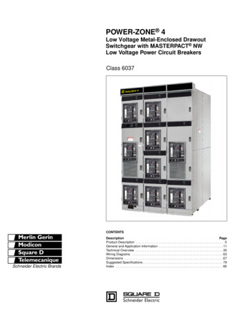
Padmount Front ONT62” for Non-SafeVu, 67” for SafeVuWith standard 36” cable compartmentWith standard 24” minimum bushing height.Add 24” width for low voltage enclosure.Dimensions are approximate.Do not use for constructionSIDEVault Front mm)60” for Non-SafeVu, 62” for SafeVuFRONTWith standard 24” minimum bushing height.Depth is 25” (635mm) standard and 35”(864mm) with SafeVuDimensions are approximate.Do not use for construction.SIDEFront Back AccessWIDTHHEIGHT66”(1676mm)FRONTDepth includes 27” cable compartmentswith SafeVu 99” (2515mm)with standard 24” minimum bushing height.Add 24” width for low voltage enclosure.Dimensions are approximate.Do not use for construction.DEPTH84”(2134mm)SIDEBACK
Contact us today 1.708.388.5010 or info@gwelectric.comSince 1905, G&W Electric has been a leading provider of innovative powergrid solutions, including the latest in load and fault interrupting switches,reclosers, system protection equipment, power grid automation andtransmission and distribution cable terminations, joints and other cableaccessories. G&W is headquartered in Bolingbrook, Illinois, U.S.A., withmanufacturing facilities and sales support in more than 100 countries,including China, Mexico, Canada, UAE, India, Singapore, Brazil and Italy.We help our customers meet their challenges and gain a competitiveedge through a suite of advanced products and technical services.gwelectric.com 2019 G&W ElectricGW10-2019 02/21
Voltage Class (kV) 15 25 35 Max. System Voltage (kV) 15.5 27‡ 38 BIL (kV) 110Δ 125 150 110Δ 125 150 Continuous Current (A) 630§ 630§ 630§ Load Break Current (A) 630 §630§ 630 AC Withstand, 1 min. (kV) 35 60 70 AC Withstand, Productions, 1 min. (kV) 34 40 50 DC Withstand, 15 min. 53 78 103 Momentary Current, RMS, asym (kA) 20 20 20