Transcription
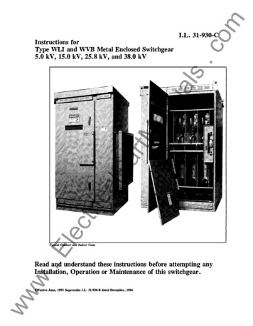
.comI.L. 31-930-C.ElectricalPartManualsInstructions forType WLI and WVB Metal Enclosed Switchgear5.0 kV, 15.0 kV, 25.8 kV, and 38.0 kVTypical Outdoor and Indoor UnitsRead and understand these instructions before attempting anywInstallation, Operation or Maintenance of this switchgear.wwEffective June, 1993 Supersedes I.L. 31-930-B dated December, 1984
PURPOSEIf further information is desired by purchaser regarding thisparticular installation, contact the local Westinghouse salesoffice. For application information, consult your nearestWestinghouse sales office, see Westinghouse DescriptiveBulletin 31-935, and read the appropriate ANSI standards.Section 5 - Maintenance.135.05.15.25.35.45.5Inspection ScheduleInspection ProcedureAlignment ProceduresReplacement ProceduresInsulated Bus MaintenanceLubricationualsThis instruction book is expressly intended to cover theinstallation, operation and maintenance of type WLI andWVB metal enclosed switchgear. It does not purport tocover all possible contingencies, variations, and details thatmay arise during installation, operation or maintenance ofthis equipment.com2Section 6 - Selector Switch Configuration.18Section 7- Duplex Configuration.18PageBasic Description and ApplicationSwitchgear IdentificationSafety FeaturesSafe PracticesSection 9 - Electromechani :al Stored Energy Release.19Section 2 - Receiving, Handling and Storage .4lP2.0 Receiving2.1 Handling2.2 StoragecaSection 3 - Installation. 4triJoining WLI EnclosuresInstallation of Roof Caps on Outdoor UnitsConn. of WLI Switchgear to TransformerConn. to AMPGARD Starter LineupConnection to Metal Clad Switchgear LineupConnection of Customer Power CableField Taping of Electrical ConnectionsSecuring WLI switchgear to FoundationConnection of Space Heaters toCustomers Source3.9 Superstructure Assembly3.10 Inspection Before Startup.Elec3.03.13.23.33.43.53.63.73.8Section 4 - Operation. 11www4.0 Safety Interlocks4.1 Switch Operation4.2 Fuse ReplacementDescriptionReceiving and StartupElectrical OperationSafety InterlockingManual .5tMSection 1- Introduction.3anSection 8 - Motor Operation.18TABLE OF CONTENTS9.09.19.29.3DescriptionOperationDoor Interlock (Shaft Blocking Cam)Inspection and MaintenanceSection 10- WVB Switchgear . 2310.010.110.210.310.410.510.6Description and ApplicationIdentificationSafety FeaturesReceiving, Handling and StorageInstallationOperationMaintenanceSection 11 - Renewal Parts.26FURTHER INFORMATIONWLI Renewal Parts Data - RPD 31-935WLI Descriptive Bulletin - DB 31-935WVB Descriptive Bulletin - DB 31-960Type VCP-W Vacuum Circuit BreakerInstruction Book - IB 32-255-1Type RBA Fuse - I.L. 36-654-1AWestinghouse Catalog 55-000Westinghouse Catalog 26-000For the location of your nearest Westingbousedistributor, call toll free 1-800-525-2000
FIELD INSIJIAT/ON INSTRIJCTIONS.comI.L. 31-930-C Supplement 1, August, 1997DEFINITIONS AND CUTLER-HAMMER APPROVED MATERIALS FOR FIELD INSULATIONFiller- Nashua No. 102 Duct Sealer or 3M Co. Scotchfil or Neer Duct Seal .J,;;;dating Tape & Pad- Either 3M Co. Scotch 23 or Scotch 130C.Insulating Boot - Molded plastic cover that is put over a joint and fastened in place with wire ties.Joint- An area to be insulated. This consists of the bare conductor and 1-1/2 inches of any pre-insulation next to the bareconductor.laps the previous tum by the amount specified in the Taping Chart.ualsLaver - Insulating tape, 1 inch wide, wrapped from one end of the joint to the other (or to a pad) so each succeeding tumOverlap- A specified distance measured along the pre-insulation starting from the point where the pre-insulation endsand the exposed conductor begins.Pad - Any insulating tape applied which is wider than one inch. Includ s a band of tape consisting of one or more turnswrapped directly on top of each other.anPre-insulation -Any insulation covering (Sleeving materials such as NORYL , RAYCHEM , SCOTCHTITE , andFluidized Epoxy Coating) adjacent to an exposed conductor prior to insulating. WARNING: Use ofsolvents, oils, joint compounds, or grease on or near NORYL insulation wi II destroy it.tMRESPONSIBILITY OF INSTALLER1) For incoming or outgoing terminations, these approved materials are not supplied by Cutler-Hammer and must beobtained and installed by others as identified above in the definitions.2) For connections involving shipping splits within a WLI Switchgear assembly, or connecting to a Transformer, or anarAl\.1PGARD MCC, or a Vac-Clad-W Switchgear assembly, or a Medium Voltage Bus Run, insulating materials willbe supplied if necessary by Cutler-Hammer. It is the responsibility of the installer to insulate the connections inaccordance with these instructions.lP3) For a switchgear assembly that does not have continuous insulating sleeving on the phase bus conductors and wherethe dimensions in the table below are not met at field assembled connections, insulation of these connections must bemade.MINIMUM CLEARANCE CHARTPhase-to-GroundPhase-to-Phase(in inches)(in inches)caKVonWLI*tri5152738*36810.536810.5EXAMPLE: If the phase-to-phase clearances above for a given rating do not exist, thenlecit is only necessary to insulate the center phase.CAUTIONFailure to install field insulation where necessary in accordance with these instructions will compromise.Ethe electrical ratings of the switchgear assembly.wInstall field insulation to maintain the electrical ratings.FIELD INSULATION METHODSMethod 1- Using an Insulating Boot:G ENERALww1. Clean area of dirt and foreign matter. Use a clean dry cloth or if necessary dampen slightly with distilled water. Dnot use any abrasives or solvents.2. Place boot over joint so it fits in place. Fasten together with plastic wire ties. Cut off excess ends of plastic w·
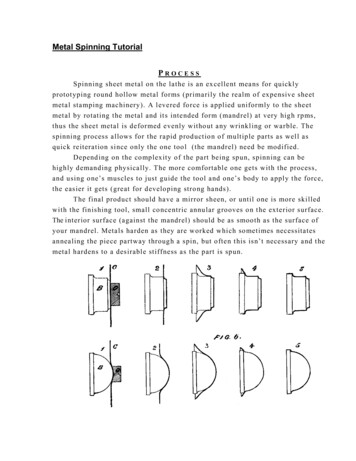
31-930-C Supplement 1, August, 1997Method 2- Using Insulating Tape and Filler:GENERAL1. Elongate insulating tape 10 to 25 percent during application to insure a smooth, tight fit.On pads elongate comers only.2. Should a tape roll expire, start the new role by overlapping the previous end by 1/2 turn.JOINT-NO HARDWARE.comI.L.1. Clean area of dirt and foreign matter. Use a clean dry cloth or if necessary dampen slightly with distilled water. Donot use any abrasives or solvents.uals2. Apply one tum of 1 inch tape so 1/2 of the tape is on the conductor and 1/2 is on the pre-insulation Overlap tapeends 1-1/2 inches.3. Apply one layer of insulating tape, lapping as specified in the Taping Chart below, overlapping any pre-insulation byl-112 inches.JOINT-WITH HARDWARE1. Clean area of dirt and foreign matter. Use a clean dry cloth or if necessary dampen slightly with distilled water. Donot use any abrasives or solvents.an2. Apply filler over bare conductor and hardware to cover and smooth out the surface. Blend contour into pre-insulationsurfaces. Cover conductors and hardware with at least 1/8 inch of filler.3. Apply pad(s) of insulating tape of sufficient width to overlap pre-insulation by one inc:h or more.4. Apply one layer of insulating tape, lapping as specified in the Taping Chart, overlapping any pre-insulation or padstMby 1-1/2 inches.TAPING CHARTI nsulating TapePre-insulationor Pad OverlapMin. I nches5OverS1-1/21-1/2No. ofLayersNo. ofPads1/22/31212calP10 ,:SljLap ofTapearKVonWLI1-1/2" (Min. Lop).Electri1-1/2"TYPICAL INSUlATING TAPEwwwTYPICAL INSUlATING TAPE AND PAD2(Min.Lap)
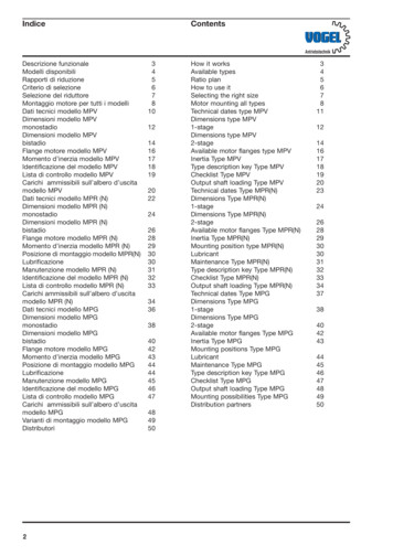
.com3SECTION 1-INTRODUCTIONWARNING1.0 Basic Description and ApplicationExceeding nameplate ratings of WLI switchgear couldcause property damage, severe injury, or death. WLIswitchgear must be operated within its nameplatedratings.Type WLI and WVB metal enclosed switchgear consist ofan air insulated, three pole, gang-operated, quick-make,metal enclosure.ualsquick-break, load interrupter switch in a floor mountedIt can be applied in combination with(WVB)power fuses or a vacuum circuit breakerand manyother protectivie devices to provide safe, uentdisconnecting means is required.1. A door interlock prevents opening the enclosure frontdoor while the switch is in the closed position.2.1.1 Switch ModiriC8tionsA switch interlock prevents manual operation of theinformation should be given to the Westinghouse salesanhandle mechanism with the door open.office if a question should arise concerning the switchgearopen or closed position.A nameplate is located inside the small access door of eachtype WLI switchgear vertical section (see Fig. 1).3. A viewing window is provided to verify each switchContained on this nameplate are the Westinghouse ordercontact position.4.Facility is provided for padlocking the switch in thetMnumber, drawing number, and switch style number. Thisor if renewal parts are required. These numbers allow thefactory to completely identify the switchgear. Also located5. Facilities are provided for padlocking the door handleson the nameplate are voltage and current ratings for theclosed.arswitch and switchgear.6.1.2 Safety FeaturesMechanical indicators7.operation.lPType WLI load interrupter switchgear has several built-infeatures to reduce hazards and to provide proper operatingWestinghouseOperating a WLI switch with a key interlock boltextended will result in equipment damage and mayalso expose a person to bodily injury or death.The key must be inserted into the interlock androtated to retract the locking bolt beforeoperating a WLI switch.tri##KV RatingNominal-lecSwitch StyleCAUTION Wll load Interrupter SwitchgearDrawingKey interlocks, when provided, force a sequence ofcasequences.Built on Ordershow whether the switchmechanism is open or closed.AmpereContinuousRating1.3 Safe PracticesInterruptingOnly qualified electrical workers with training and expe B.I.L.Momentaryrience on high voltage circuits should be permitted to work.EMaximumFault CloseWestinghouse Electric Corp.Distribution Equipment Div.sfi7274A77H01w wwFig.Sumter, S.C. U.S.A.1 Typical Nameplateon this equipment. They should be familiar with the workto be performed, the safety equipment required, andhazards involved.1. Read and understand these instructions before attempt ing any assembly, operation,switchgear.Exceedingor maintenance of thisnameplateratingsofWLIswitchgear could cause property damage, severe injury, ordeath.
There are several inurlocks on the swiJches. They arefor personnel and/or equipment prouction. Under nocircumstances should they be nuule inoperative whenswiJch is in service. To do so could cause bodily injury orproperty damage.4. Never energize the switch without thebarriers installed.arcchutes andIf it is necessary to store the equipment before installa tion, keep it in a clean, dry location with ample air circu lation and heat to prevent condensation. Like all electricalapparatus, these units contain insulation which must beprotected against dirt and moisture. OUTDOOR UNITSuals3. After opening switch and before opening door, useviewing window to insure that all three switch blades areopen. If necessary, use a flashlight to verify all threecontacts are open.2.2 StorageMAY BE STORED OUTSIDE ONLY IF ROOF CAPSARE INSTALLED, SPACE HEATERS ENERGIZED,AND ANY OPENINGS ARE ENCLOSED.SECTION 3- INSTALLATIONRefer to shipping list (Form SUM-T-3) for location of bus,hardware and all other joining and installation material.an2. Disconnect all power sources before making any adjust ments or performing maintenance.com43.0 Joining Type WLI or WVB EnclosuresS. Always be sure that all hardware is in place and bolted3.0.0 Access to WLI switch Vertical Sections Containingtightly before putting switch into operation.tMSwitchesSECTION 2 RECEIVING, HANDLING ANDSTORAGElP-2.0 ReceivingtricaA visual inspection - inside and out - should be performedimmediately upon receipt of the switchgear and beforeremoving it from the truck. Shipping papers should bechecked to be sure all boxes or other accompanying pieceshave been received. If any damage or shortages areevident, a claim should be flied at once with the carrier,and the nearest Westinghouse sales office notified.lecThe order data nameplate for each switch assembly islocated inside or on the access door. The order numberand drawing number are located on this nameplate andshould be given to the Westinghouse representativewhenever identification of the assembly is required.E2.1 HandlingwRemovable lifting plates are provided on the top of theWLI or WVB structure for insertion of hooks to lift thecomplete structure. This is the only recommended methodof moving the WLI or WVB structure. Extreme careshould be used not to damage of deform the unit if othermoving methods are employed.wwEach WLI switch is shipped from the factory in the closedposition to maintain alignment during shipping and handling.The safety interlocking prevents opening of the door of thevertical section when the switch is closed. In order to gainaccess to the interior, be sure the switchgear is on a truear6. Before replacing covers, carefully inspect buswork andphase barriers to insure that no tools or other objects areaccidently left inside the unit.and level surface. To open a manually operated WLI switchinsert the operating handle and push down. When the switchopens the door may be opened. If the switch is equipped withan electro-mechanical stored energy release feature, followthe instructions on the label inside the small access door,starting at the section" switch closed, spring discharged" toopen switch. If the switch is motor operated, open the motorcompartment door where the motor operator is housed,remove handle, insert in the manual operating port andpush down to open switch, being sure any key interlockbolts, if supplied, are retracted before attempting to operatethe switch. H the switch is motor operated with the electro mechanical stored energy release device, insert handlein operating port and push down. An audible"clunk" willbe heard as the operating mechanism engages its releasetrigger. To access the trigger, it will benecessary to removea small access cover on the side of the motor cabinet, thenstick a screw driver or similar lever tool through the openingto lift the trigger.When handling WLI switchgear, be sure the switches are inthe closed position. Do not operate WLI switches unless theyare setting on true and level surfaces.3.0.1 Identification of Shipping SplitsRefer to the front view drawing. Below this drawing,shipping splits will be identified in relation to groupnumbers for each cubicle. Normally shipping sections willnot exceed 154 inches in width.3.0.2 Procedures for Joining WLI or WVB Enclosures atShipping Splits (Refer to Fig. 2)
.com5figures detail the work to be done to install each cap.a. Remove the lifting plates from the WLI assembly andreplace the bolts.b.Place a roof cap in position and start enough screwsit in place.c.uals(provided loose in a hardware package) to temporarily holdDraw a pencil line down the side(s) on to the roof tomark the edge(s) of the cap on the roof. (Fig. 3)IanMountingBoltstMFig. 2 Joining WLI Enclosuresara. Remove the eight 3/8 inch bolts from each side sheet.b. Position the shipping sections next to each other. Theeight holes will match holes in adjacent side sheets.Bolt the side sheets together using the eight boltsd.lPc.removed from one side sheet.Make main and ground bus connections using splicesilver plated.careBus bar is usually tin orcaplates and hardware furnished.To insure a proper electrical connection,should be taken to protect the plating from damage.triDO NOT use joint compound.CAUTIONRemove roof cap and apply a 114" bead of caulkinge.Hold the edge of the roof cap adjacent to the pencilline, then rotate over onto the bead(s) of caulk, aligningwith the bolt holes in the roof as the action is completed.(See Fig. 4)Bolted connections should be tightened to the torque.Ee.lecCleaning bus joints with abrasive or chemicalcleansers may remove plating, which may causejoint overheating. Wipe with clean, dry clothto clean off surfaces.d.along the inside edge of the pencil line(s). (Tubes providedby Westinghouse loose)values given in Appendix A.f. Put in bolts and gasketed washers (rubber side towards3.1 Installation of Roof Caps on Outdoor Units.to 5 ft-lbs.roof cap) in every bolt hole of roof cap. Tighten the boltsg.smooth out any excess caulk along edges of the roof cap.wRoof caps are necessary to complete the roof of all outdoorWLI switchgear assemblies. Those not factory installed areFollowing instructions on the caulking container,shipped in cartons which may be put within one or moreContinue this procedure until all roof caps have beeninstalled.wwvertical sections if there is space, or they will be shippedseparately.The following procedure and accompanying
Removable Plate and Seal forMaking Electrical Connections.com6Felt andTransformer ThroatualslH.V.H.V.SwitchSwitchThroatanSealing SectionAdhesive TapetMFig. 4 Roof Cap lnsUJllalionFelt andFig. 5 Transformer Connection to WLI Switchb.Since factory cables are unshielded, they must beproperly separated from each other, from all groundedarmetal parts, and from transformer bushings/terminals of3.2 Connection to Type WLI Switchgear toTransformerother phases.c.Physical Connection3.2.1.1lP3.2.1Indoor AssembliescaHoles are predrilled in the side of the WLI structure toType WLI switchgear conforms to ANSI standardsconcerning phasing. Phases are arranged A, B, C, front torear, top to bottom, and left to right at connection pointsunless otherwise noted on the drawings.responsibleformaintainingThe installer iscontinuityofphasingthroughout the system.match holes provided in the transformer.3.2.1.2Switch and transformer should be brought together totria.Outdoor Throat Connection (See Fig. 5)d. Lugs are provided with the switchgear for terminatingcable to the transformer bushings/terminals.3.2.2.2Connection by Bus Bargive spacing or 112 inch between throat flanges.a. Splice plates and hardware are furnished with the WLIApply double adhesive tape supplied with WLI.Elecb.switchgear.switchgear to outside surfaces of both flanges.c.b.Press felt supplied with WLI switchgear into place onadhesive tape. Felt is to seal against entrance of dust ll sealing ring removed prior to mating the flangesin "a" above.3.2.2 Medium Voltage Electrical ConnectionsConnection by Cable Supplied with Type WLIw3.2.2.1Switchwwa.Cables arerullfactory pre-cut to proper length.Installer !!1!!§! cut to fit.To insure a properplating from damage. Refer to para 3.0.2.d.bytransformer resonance to the WLI switchgear.d.Bus bar is tin or silver plated.electrical connection, care should be taken to protect thec. All bolts should be tightened according to Appendix A.3.3 Connections to AMPGARD Medium Voltage MotorControl Center.a. Holes are predrilled in the side of the WLI switchgearstructure to match holes provided in the MCC.Bolttogether using hardware furnished with WLI switchgear.b. Make bus connections per Section 3.2.2.2.
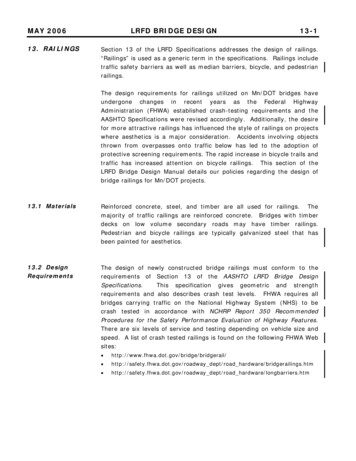
.com73.4 Connections to Metal Clad Switchgear Assembly3.5 Connection of Customer Power Cables3.4.1 Indoor Switchgear- Follow Same ProcedureCable termination space is provided in the cubicle for topOutlined in Section 3.3.or bottom cable entry as shown on the drawings. Adequateelectrical clearance must be maintained between cables,3.4.2 Outdoor Switchgear (See Fig. 6)energized parts, and grounded metalparts.It is also thea.Position units side by side. Holes in WLI side sheetaround bus cutout will match holes in metal clad switch ualsinstaller's responsibility to adequately support cables suchthat insulators or bus bars do not carry the strain of thecables.gear flange.Tin-plated aluminum clamp type terminals are supplied asb.Press sponge neoprene gasketing tape supplied withWLI on to flange for weather-tight seal.standard and are suitable for acceptance of copper oraluminum cable. If potheads or other special terminationsare supplied, termination should be made according to theOpposite side of metal clad switchgear flange has nutsanterminator manufacturer's instructions.c. Join enclosures using bolts supplied with WLI.welded in place for ease of connection.3.6 Field Taping of Electrical Connections (See Fig. 7)d. Make bus connections per Section 3.2.2.2.Field taping of electrical connections should be done wheretMshown on drawings, or as tagged by the factory inspector.Taping materials are supplied with the WLI assembly.lPSuppliedbyWLIcaMetal SuppliedbyWLIw.EIIIIIIIGasketwwFig. 6 Connection 10 Metal Clad Switchgear lineup OUldoor UnitLapF g. 7 Field Taping ofElectrical Connections3.6.1a.MaterialsFiller - insulation puttyInsulating tape- black, linerless H.V. EPR tape, 1"b.wide.3 .6.2 Procedurea.Clean area of dirt and foreign matter per Section 5.4.b. Apply filler over bare conductor and hardware to coverandsmoothoutthepreinsulation surfaces.surface.BlendcontourintoCover conductors and hardwarewith at least 118" of filler.c. Apply insulating tape, lapping and layering as specifiedin the chart. Tape must overlap factory installed insulationby 1 " .Elongate insulating tape 10 to 25 percent during
.com8application to insure a smooth, tight fit. Should a tape rollFor lineups or units with heater control devices, heatersbe used up, start the new roll by overlapping any previouswill be internally wired and brought to a terminal block.end by 112 tum.A wiring diagram will be furnished with the drawingsshowing connection points for power.Lap of Tape.1, 9,,6 1No. ofLayersUp to 5 kV1/21OverS kV to2/32r38 kv3.6.3 Factory installed insulation may be NORYL, a high thermoplastic.ItcanbetMengineeringirreversibly damaged if it comes in contact with certainchemicals.See Section 5.4 for cleaning procedures.WLI Outdoor Basean4"performanceualsCbart 1 Taping Oum l0arWARNINGlPUse of solvents, oils, joint compounds, or greaseson or near NORYL insulation will destroy it. Cleanonly with water or isopropyl alcohol.ca3.7 Securing WLI or WVB Switchgear Assembliesto Foundations0 16o.v l0\70\)I\7\7\7."'0I t IIIIII''IIa0/.'Q"'·0 I0--·'r'' .'''IIIII ;)00I'I'0\j-v000C F g. 8 Bolting WLI or WVB Unit to FoundationAll anchoring hardware and necessary devices are to besupplied by the installer.1/2" anchor bolts.be secured to the foundation usingtri3.7.1 Indoor unitscan3.9.1 ReceivingThe four 5/8" holes in the base forthese bolts are shown on the floor plan included with theCheck to see that all parts necessary for assembly havebeen received.lecdrawings.3.9 Superstructure assembly (See Figs. 9A and 98)The packing list will show all requireditems (bus, hardware, phase barriers, taping material, etc.)3.7.2 Outdoor units are secured using clips and foundationand will indicate in which shipping unit the various partsbolts as shown Fig. 8. Lead anchors and lag screws mayare located.be used in place of J-bolts if desired.3.9.2 Installation of Superstructure.E3.8 Connection of Space Heaters to Customers Sourcea. If a lineup, join per Section 3.0.Space heaters, when supplied, must be energized toSecure switches tofoundation per Section 3.7.prevent condensation. Heaters are supplied for 120 or 240volt sources as shown on drawings.singlewForunitsb. Remove top sheet from switch unit.On indoor unitsthis top sheet will later be re-installed on the superstructurewithnoheatercontrolusing the same mounting hardware.Outdoor units areshipped with the roof attached to the superstructure. Thethe installer must wire directly to terminals on the spacetop sheet on the switch is used for shipping purposes only,heater.and may be discarded aftei' removal.wwdevices,(thermostats, circuit breakers, or safety switches),
.com9c. Remove lifting eyes and replace mounting bolts afterremoval.d. Remove superstructure from the shipping pallet and thenremove all bolts covers from it.Shipment of more thanone WLI will be tagged to identify superstructures withtheir corresponding switch units.Install superstructuretappingualsatop switch using the bolts, nuts, washers, and/or selfscrewsasprovided.Occasionallythesuperstructure assembly will become slightly "sprung" inshipment so that it does not align exactly with the top ofthe switch enclosure. If this should occur, install bolts orscrews in all holes that align then use a pinwrench to pryadjacent holes into alignment.2-(0.0.Units7-3.9.3Lower Phase BarrierAll bus sections have been assembled at the factory and8- Nylon Bolts and NutsOnly)Bus Support Insulator9-4- Phase Bus Riserschecked for clearance prior to shipment.Upper Switch TerminalPad3 -Main Horizontal Bus10 - lncom ing Line Bus5 -Upper Phase Barrier6- Nylon Separator Rod11-Bus assemblyan-Roof Capa. Units without horizontal main bus require installation ofIncoming CabletM1one piece of bus section per phase from the upper switchTerminationterminal pad to the incoming line termination. Each phasebus is attached in two places-to the upper switch terminalFig. 9A Section View, Superstrucrure Assemblypad and to the bus support insulator mounted in thearsuperstructure. Use the bolts provided.b. Units with main bus also require horizontal bus sectionsw.ElectricalPbolted to the bus support insulators. Phase bus risers arewwFig. 9BFront View, Superstrucrure Assemblythen bolted from the switch terminal pad to the mainhorizontal bus. Lineups shipped in more than one sectionwill be supplied with horizontal bus lengths correspondingto widths of shipping sections.After installation, joinhorizontal bus sections using splice plates provided.c. Tighten all bolted bus connections to torque values givenin Appendix A.d. Bus requiring field taping will be identified by a redtaping tag.Taping material will be provided and tapingprocedures described in Section 3.6 should be followed.3.9.4 Upper Phase BarrierInstallationRemove upper nylon separator rod using "E" rings tosecure to phase barriers.Barriers should be alignedstraight and true with maximum clearance from live parts.3.9.5 ReplacingCoversCAUTIONBefore replacing covers, carefully inspect buswork andphase barriers to insure that no tools or other objects areaccidentally left inside the unit.
.com10a. Install roof and covers using hardware provided.b. Install roof caps on outdoor units per Section 3.1.3.10 Switch Inspection Before Startupshipment.However, vibration and mechanical stressesimposed by transit and installation can adversely affectualsEach switch is properly adjusted at the factory before1/16"-1/8"switch adjustment; therefore, a fmal inspection is essentialbefore energizing. If this inspection reveals any defects gnment procedures in Section 5.2.tMMainSwitchShaftF"ag. 11 Drive Rod Links and Shaft Ears Alignmenzopening it using the maintenance hub as described inarSection 5.1.3.c. In the closed position the drive rod links and shaftearscalPmust be 1116" to 1/8" over toggle when checked with astraight edge(see Fig. 11).d. With the switch closed, the upper spacers of the mainblades should rest 3/16" 1116" above the bottom of thedepression of the stationary break jaw (see Fig.12).triInspection procedures require closing and opening theswitch with the main door open. This requires override ofthe switch safety latch as described in Section 5.2.1 andlecmust be accomplished before energization.Inspection Procedure:a. With switch in the open position(see Fig.10) the distancebetween the edge of the main blade and the closest point of.Ethe break jaw should be:w6-518" -If- 118"for 5 kV switches6-314" - 7- 118"for 15 kV switches11-112" 1- 118"for 25 and 35 kV switchesb. Main and flicker blades must be in proper alignmentwith break jaws and arc chute openings respectively. Thiswwcan be checked by closing the switch and then partiallyr
.com11e. Check bolted bus connections for proper tightness,referring to Appendix A for torque values.f. If fixed mounted fuses are supplied, check the plasticknobs that hold fuses in place. They should be hand tight.g. If disconnect fuses are supplied, check to see that theycompletely latched closed.ualsareh. For units fitted with expulsion-type, boric acid fuses,check the discharge fllters on the lower end of the fuses fortightness. They must be securely hand tightened.i.Check to see the space heaters,ifsupplied,arej. Wipe away any dust or dirt that may have accumulatedin compartment(s) paying particular attention to insulatorsand insulating material. If bus is insulated, see Section 5.4tMfor cleaning procedures.anenergized.k. A final thorough inspection should be made to insurethat no tools or other objects are accidentally left inside theFag. 13 Safety Latch Locationarenclosure.4.0.2SECTION 4 - OPERATIONDoor InterlocklPThis interlock prevents the door of the enclosure frombeing opened when the switch is closed. When the switch4.0 MECHANICAL SAFETY INTERLOCKSis closed, a cam welded to the operating shaft engages aThe WLI switch is equipped with switch interlocks andthe door from being opened.(See Fig.14.)cadoor interlocks as well as provisions for padlocking ineither the open or closed position.triWARNING.ElecDefeating or disengaging safety interlocks on aWLI switch that is connected to a power source mayresult in property damage, bodily injury or death.Do not defeat or disengage any safety interlocks.4.0.1Switch InterlockThis interlock prevents inadvertent closure of the switch ifthe enclosure door is open. When the door is closed, thepointed latch lug welded to the inside of the door causesthe safety latch to move out of the blocking position(seewwwFig.13).bracket welded to the inside of the switch door, preventing
.com124.1. Switch OperationKey
office if a question should arise concerning the switchgear or if renewal parts are required. These numbers allow the factory to completely identify the switchgear. Also located on the nameplate are voltage and current ratings for the switch and switchgear. 1.2 Safety Features Type WLI load interrupter switchgear has several built-in