Transcription
MDM X3Modular Dual MobilityAcetabular System Surgical protocol Catalog
MDM X3 Modular Dual Mobility Acetabular System Surgical protocolHomeMDM X3 Mobile Bearing Hip Systemsurgical protocolTable of contentsIntroduction.4Step 1 Preoperative planning and X-ray evaluation.5Step 2 Acetabular preparation.5Step 3a Spherical reaming.6Step 3b Final reaming.8Step 4 Trial evaluation.9Step 5 Shell implantation. 10Step 5a Optional screw utilization. 12Step 6 Trial insert reduction. 14Step 7 Liner implantation. 14Step 8 Trial insert/head reduction. 16Step 9 Insert/head implantation. 19Step 10 Reduction and closure. 20Removal options. 21Catalog information.22This publication sets forth detailed recommended procedures for using the MDM X3 Modular Dual Mobility AcetabularSystem. It offers guidance that you should heed, but, as with any such technical guide, each surgeon must consider theparticular needs of each patient and make appropriate adjustments when and as required.2
MDM X3 Modular Dual Mobility Acetabular System Surgical protocolHomeTOCIndications, contraindications and precautionsINDICATIONS for US and Restof WorldContraindicationsThe indications for use in total hiparthroplasty include:2. Distant foci of infections (whichmay cause hematogenous spread tothe implant site);1. Noninflammatory degenerativejoint disease includingosteoarthritis and avascularnecrosis;2. Rheumatoid arthritis;3. Correction of functional deformity;1. Overt infection;3. Rapid disease progression asmanifested by joint destructionor bone resorption apparent onroentgenogram;4. Skeletally immature patients; and4. Revision procedures where othertreatments or devices have failed;and,5. Cases where there is a loss ofabductor musculature, poor bonestock, or poor skin coverage aroundthe hip joint which would make theprocedure unjustifiable.5. Treatment of nonunion, femoralneck and trochanteric fracturesof the proximal femur with headinvolvement that are unmanageableusing other techniquesConditions presenting increasedrisk of failure include:6. Dislocation risksMDM Liners are intended forcementless use only.INDICATIONS for EU, EMEAcountries requiring CE Mark,and AustraliaThe indications for use in total hiparthroplasty include:1. Noninflammatory degenerativejoint disease includingosteoarthritis and avascularnecrosis;2. Correction of functional deformity;3. Revision procedures where othertreatments or devices have failed;and,4. Dislocation risksMDM Liners are intended forcementless use only.1. Uncooperative patient or patientwith neurologic disorders, incapableof following instructions;2. Osteoporosis;3. Metabolic disorders which mayimpair bone formation; and4. Osteomalacia.Warnings and precautionsSee package insert for warnings,precautions, adverse effects and otheressential product information.Additionally, the MDM Liner is notintended for use as a metal-on-metalor ceramic-on-metal articulation.No testing has been conducted todetermine that these bearing couplesproduce favorable mechanicaloutcomes. Only Stryker 22.2mmor 28mm femoral heads should beinserted into the MDM X3 polyethyleneinserts. Further, do not substituteanother manufacturer’s device for anycomponent of the MDM AcetabularSystem. Any such use will negate theresponsibility of Howmedica OsteonicsCorp. for the performance of theresulting mixed component implant.Before using MDM instrumentation,verify: Instruments have been properlydisassembled prior to cleaning andsterilization; Instruments have been properlyassembled post-sterilization; Instruments have maintaineddesign integrity; and, Proper size configurations areavailable.For Instructions for Cleaning,Sterilization, Inspection andMaintenance of Orthopaedic MedicalDevices, refer to LSTPI-B, and SLI0001.Acetabular shell compatibilityThe MDM Liner is intended for usewith Trident, Trident Tritanium,Restoration Anatomic, and TridentII shells only. The MDM surgicaltechnique should be used in conjunctionwith the desired Stryker AcetabularShell System surgical technique forcomplete guidance on using the shellimplant, including technique andinstrumentation.For indications for use of associatedproducts in this protocol, please referto the following instructions for use(IFU) numbers enclosed within productpackaging, or visit ifu.stryker.com: Trident shells: QIN 4350Trident Tritanium: QIN 4350(multihole)Trident Tritanium: QIN 4397 (solidback& clusterhole)Restoration Anatomic shells: QIN 4422Trident II shells: QIN 44303
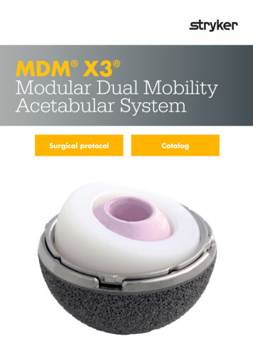
MDM X3 Modular Dual Mobility Acetabular System Surgical protocolHomeTOCIntroductionThis surgical protocol is a guide to using the MDM Acetabular system with Trident and Trident Tritanium Acetabular systems.For guidance on implanting the acetabular shells, refer to the respective Trident and Trident Tritanium Acetabular systemsurgical techniques.For MDM use with Restoration Anatomic and Trident II Acetabular systems, refer to their respective surgical techniques.Table 1: MDM Liner and Insert compatibility with Trident and Trident Tritanium ShellsShell size (mm), liner alpha codeTrident PSL Shell4446, 4850, 5254, 5658, 6062, 6466, 6870, 72Trident Hemispherical Shell4648, 5052, 5456, 5860, 6264, 6668, 7072, 74Trident Tritanium Hemispherical Shell4850, 5254, 5658, 6062, 6466, 6870, 7274-80Liner Alpha CodeCDEFGHIJMDM CoCr Liner36C38D42E46F48G52H54I58JX3 Poly Insert OD (mm)3638424648525458X3 Poly Insert ID (mm)22.222.2282828282828Nominal poly thickness (mm)6.77.76.88.89.811.812.814.8Design rationaleThe MDM System is designed to incorporate the followingdual points of articulation: 22.2mm or 28mm femoral head; and, Large polyethylene insert that mimics a femoral head.Acetabular shellMDM CoCr LinerPoly insertFemoral head4
MDM X3 Modular Dual Mobility Acetabular System Surgical protocolHomeTOCStep 1Preoperative planning and X-rayevaluationPreoperative planning is an essential part of the procedure,and templating should be performed prior to everycase. The preoperative planning process should takequalitative and quantitative factors (including patientbone quality, density and morphology) into considerationin order to evaluate and select the appropriate instrument/implant system for the patient. X-ray evaluation may alsohelp detect anatomic anomalies that could prevent theintraoperative achievement of the established preoperativegoals. Selecting potential implant style and sizes canfacilitate operating room preparation and assure availabilityof an appropriate selection. When it is done using X-raysthat have been suitably scaled for magnification, templatingallows the surgeon to predict the style, size and position ofthe implant that may help restore the correct anatomy of theindividual patient.Template planning can be done using acetate templates forprinted X-rays or preoperative planning software for digitalstudies.Use the appropriate Acetabular Shell System templateoverlay (listed in section Catalog Information) availablethrough your Stryker representative.NoteCareful identification and removal of osteophytes can helpreduce the possibility of bone-to-bone or component-to-boneimpingement.Additionally, this can aid in the identification of bony landmarksused for cup positioning.Step 2Figure 1Acetabular preparationThe acetabulum is prepared by the release and removal ofsoft tissue using the surgeon’s preferred technique to gainadequate exposure for reaming. Excision of the labrumand osteophytes allows for proper visualization of the bonyanatomy and improves ease of reaming.Stryker Orthopaedics retractors can be utilized to gainacetabular exposure (Figure 1). With the acetabulumexposed, bony defects can be identified.If necessary, bone grafting options may be considered.5
MDM X3 Modular Dual Mobility Acetabular System Surgical protocolHomeTOCStep 3aSpherical reamingCautionOnly the CuttingEdge Spherical Reamers should be used to preparethe acetabulum for the Trident or Trident Tritanium AcetabularShell components.To help obtain recommended component positioning in thereaming process, a 45 /20 Abduction/Anteversion AlignmentGuide can be attached to the CuttingEdge Reamer Handle(Figure 2).The Alignment Guide, when perpendicular to the long axis ofthe patient, is designed to orient the reamer handle at 45 ofabduction, thereby placing the axis of the spherical reamerat 45 of inclination (Figure 3). The reamer handle may bepositioned at 20 of anteversion by aligning the left/rightanteversion rod on the Alignment Guide so that it is parallelto the long axis of the patient.It is recommended that the initial reaming begin with aCuttingEdge Spherical Reamer that is 4mm smaller thanthe templated or gauged size. The reamer is attached to thereamer handle by pushing down on the reamer and applyinga quarter-turn to lock in place. Reaming progresses in 1mmincrements until final sizing is achieved. Surgical judgmentis used to assess bone stock, amount of interference,adequacy of medialization and proper amount of reaming asdesired.Figure 245 CautionTo help ensure proper functioning of the external AlignmentGuides, the patient must be in a lateral decubitus position withoutpelvic tilt.Figure 3NoteChanges in pelvic tilt and pelvic flexion caused by patientpositioning on the table, as well as disease in contralateralhip, spine and pelvis may impact a surgeon’s ability to achievecomponent placement of 45 /20 abduction/anteversion.TipCheck for and remove internal osteophytes prior toreaming for the implant to prevent lateralizing the shell.6
MDM X3 Modular Dual Mobility Acetabular System Surgical protocolHomeTOCStep 3aSpherical reaming (continued)The full profile of the CuttingEdge Spherical Reamernecessitates reaming to the full depth. The reamer headshould be driven to the point where the rim/cross bar contactsthe acetabular wall at the peripheral lunate region. Removalof the reamer from the handle is performed by pulling backon the locking sleeve and rotating the reamer head a quarterturn in a clockwise direction (Figure 4).Care should be taken so as not to enlarge or distort theacetabulum by eccentric reaming. Final acetabular reamingideally shows the hemispherical acetabulum denuded ofcartilage, with the subchondral plate preferably intact, andthe acetabular walls preserved.LockingsleeveNoteThe CuttingEdge Spherical Reamers are very aggressive andperform best when sharp. Care should be taken to protect thereamer from unnecessary handling, as dull or damaged cuttingteeth may cause improper reaming. Dull cutting teeth will deflectto cut softer bone and resist hard bone. This situation may resultin an irregularly shaped or enlarged acetabulum preparation.Figure 47
MDM X3 Modular Dual Mobility Acetabular System Surgical protocolHomeTOCStep 3bFinal reamingTrident Tritanium Solidback, Clusterhole,and Multihole shell:Full surgical techniques for the Trident TritaniumSolidback, Clusterhole and Multihole shells can befound in the product-specific surgical protocols.When implanting the Tritanium Solidback, Clusterhole orMultihole, it is recommended to under-ream by 1mm. Aswith all manufacturing processes, due to the nature of thecoating, the outer diameter may be slightly larger than thesize indicated. The surgeon should consider this duringacetabular preparation. Depending on acetabular bonequality, the surgeon may choose to ream line-to-line.When osteoporotic bone is encountered, it is recommendedto under-ream by 1mm. When sclerotic bone is encountered,it may be difficult to fully seat the shell with a 1mminterference fit. In this situation, it is recommended to reamline-to-line to reduce the potential for problems that maytypically occur in dense bone. Potential challenges implantingacetabular shells may include: acetabular fracture, failure tofully seat the implant or slight deformation of the titaniumshell, making seating the insert more difficult.NoteThe amount of interference fit for Trident and TridentTritanium Acetabular Shells should be determinedintraoperatively based upon the patient’s bone quality.Trident Hemispherical:Full surgical technique details can be found in theTrident Hemispherical surgical protocol.Under-reaming by 1 to 2mm of the actual TridentHemispherical shell size is recommended to achieveinterference fit.Trident PSL:Full surgical technique details can be found in theTrident PSL surgical protocol.The Trident PSL HA shell periphery is 1.8mm larger thanthe stated size (e.g., 52mm shell 53.8mm periphery atthe rim of the shell). The size of the Trident PSL HA shellselected should be the same as the largest diameter of theCuttingEdge Spherical Reamer used. Surgical judgmentis used to assess bone stock, amount of interference andproper amount of reaming as desired. When implantingthe Trident PSL HA shell, the 1.8mm of interference fit isnot always necessary when dense, hard, sclerotic bone isencountered.8
MDM X3 Modular Dual Mobility Acetabular System Surgical protocolStep 4Figure 6Following the reaming procedure, the appropriate Tridentor Trident Tritanium Window Trial (Tables 2-3), of thesame diameter as the final implant size, is threaded ontothe CuttingEdge Shell Positioner/Impactor and placedin the acetabulum to evaluate the size and congruity ofthe preparation (Figure 5). The trial is “windowed” forvisualization and assessment of fit, contact and congruencyof the trial within the acetabulum. By inserting theappropriate-sized MDM Liner Trial into the Window Trial(Figure 6), joint mechanics can be evaluated. The MDM LinerTrial is designed with two forceps holes in the dome to assistwith insertion and removal. The MDM Liner Trial can beinserted and removed manually or with the use of standardforceps. Trial insert and head reduction can be facilitatedat this point – please refer to Step 8 for more detailedinformation.Table 2:Trident Window Trial/Trial Liner liner sizingWindow 08-2070A2208-2072ATOCTable 3: Trident Tritanium Window Trial/TrialLiner sizingTrial evaluationFigure 5HomeTridentWindow TrialOD (mm)444648505254565860626466687072Trial Lineralpha codeCDDEEFFGGHHIIJJWindowTrial 722208-40732208-4074TritaniumWindow TrialOD 7071727374Trial Lineralpha codeCCDDDDEEEEFFFFGGGGHHHHIIIIJJNoteTrident Window Trials are black and Trident TritaniumWindow Trials are green.NoteThe MDM trials are marked ‘trial do not implant’. If thereis any reason to believe that the trial has been accidentallyimplanted, the MDM Liner Trial is radiopaque and would bevisible on an X-ray.Table 4: MDM Liner trialsMDM Liner 52H3200-54I3200-58JAlpha codeCDEFGHIJ9
MDM X3 Modular Dual Mobility Acetabular System Surgical protocolHomeTOCStep 5Shell implantationAfter completing the trial reduction, select the appropriatelysized Trident or Trident Tritanium Acetabular Shell asclearly identified on the product label. Ensure the patient isin the correct position. At this step it is prudent to reassesspatient positioning in the surgical field. If desired, theCuttingEdge Abduction/Anteversion Alignment Guide canbe attached to the CuttingEdge Shell Positioner/Impactor tohelp establish the recommended 45 of abduction/inclinationand 20 of anteversion (Figures 7 and 8).Assess the acetabulum and surrounding soft tissue priorto shell introduction to ensure nothing is preventingshell implantation. During shell introduction into theacetabulum, minimize damage to the shell coating byinstrumentation such as retractors, and avoid draggingthe roughened surface across soft tissue.Figure 7CautionThe Alignment Guide may yield inaccurate placement if thepelvis has moved from the original position during intraoperativemanipulation. Small changes in pelvic flexion will greatly affectanteversion. The Alignment Guide is only one aid to assist withproper implant positioning. The surgeon must also rely on anatomiclandmarks to avoid improper positioning of components.NoteProper positioning of the Trident or Trident Tritanium AcetabularShell will minimize potential impingement and help to providedesired stability and articulation between the insert and head. Aswith any acetabular system, excessive vertical orientation and/or anteversion of the shell should be avoided as this may lead topremature wear of the insert material.Figure 8The Trident or Trident Tritanium Acetabular Shell isthreaded onto the impactor at the threaded hole in thedome of the metal shell. It is important to fully engage thethreads and seat the impactor against the shell. Failure tofully engage the threads and seat the impactor could resultin thread damage and subsequent difficulty removing theimpactor from the shell. If the clusterhole screw pattern shellis utilized, the holes are intended to be oriented superiorly(Figure 9).Figure 910
MDM X3 Modular Dual Mobility Acetabular System Surgical protocolHomeTOCStep 5Shell implantation (continued)The recommended metal shell abduction angle of 45 is determined by positioning the Alignment Guideperpendicular to the long axis of the patient (Figure 10).Metal shell anteversion is set at approximately 20 bymoving the cup impactor so that the left/right anteversionrod is parallel to the long axis of the patient (Figure 11). Themetal shell is impacted into the acetabulum using a malletuntil a tight, stable, press-fit is achieved. The thumbscrewon the Alignment Guide is then loosened to remove theguide. After removing the guide, the impactor handle iscarefully unthreaded from the shell.TipWith any high friction interface, the potential for the cup tochange position during insertion is possible due to differential bone densities. Care should be taken to monitor position so that changes can bemade as necessary.While the Alignment Guides are of some assistance, it is importantto critically evaluate anatomic landmarks before placement of theacetabular component. These anatomic landmarks include the anteriorand posterior walls of the acetabulum, the sciatic notch, the floor and/oracetabular fossa of the acetabulum.45 90 Figure 10A/P view20 Figure 11Lateral viewThe depth of the shell seating may now be determined byviewing through the threaded hole in the dome. If it isdetermined that the shell is not fully seated, the CuttingEdgeFinal Cup Impactor may then be required to assist inimpacting the shell until it is completely seatedin the prepared acetabulum. If utilizing the optionalAcetabular Dome Hole Plug, insert into shell implantthreaded dome hole with a Stryker Orthopaedics Torxscrewdriver, and assess that the plug is fully threaded intothe shell to prevent liner impingement.11
MDM X3 Modular Dual Mobility Acetabular System Surgical protocolHomeTOCStep 5aOptional screw utilizationIf implanting a Clusterhole shell with screws, then onlyStryker Orthopaedics Bone Screws can be used. Torx BoneScrews (2030-65XX-1) are designed to be compatible withTrident Hemispherical, Trident PSL and Trident TritaniumClusterhole shells (Table 5, Figure 12). Gap Torx BoneScrews (2080-00XX) are only compatible with TridentTritanium Multihole shells (Table 6, Figure 12). StrykerOrthopaedics offers 6.5mm diameter Cancellous BoneScrews which are available in a variety of lengths. StrykerOrthopaedics Cancellous Bone Screws are designed to beinserted or removed only with the assistance of StrykerOrthopaedics screw instruments.Figure 12Torx screwheadCautionDo not use Stryker Torx Bone Screws (2030-65XX-1) with TridentTritanium Multihole shells.Table 5: Stryker Torx 6.5mm Bone Screws foruse with Trident Hemispherical, Trident PSLand Trident Tritanium Clusterhole shellsTable 6: Stryker Gap Torx 6.5mm Bone Screwsfor use with Trident Tritanium Multihole shellsCatalognumberScrew lengths(mm)CatalognumberScrew 012
MDM X3 Modular Dual Mobility Acetabular System Surgical protocolHomeTOCStep 5aOptional screw utilization(continued)NoteAfter determination of the proper site for screw placement,a 3.3mm diameter drill is passed through a drill guide tothe desired depth (Figure 13). It is important to use theappropriate drill guide to keep the pilot hole as straight aspossible so that the screw head fully seats. The depth ofthe hole is then assessed using a depth gauge. The properlysized screw is then selected and implanted into the boneusing a Stryker Orthopaedics Screw Driver. After screwimplantation, assess that the screw head is seated flushagainst the shell to help prevent improper seating of theMDM Liner.Trident Tritanium Acetabular Shells are not intended to be drilledthrough.In hard bone, the use of 6.5mm dome screws prepared in theusual fashion may be difficult. The use of a 4.0mm drill bit canmake the utilization easier without substantial compromise ofscrew purchase.CautionDo not pass a drill, screw or any other instrumentation beyondthe inner table of the pelvis. Malposition of either the shellscrew hole orientation, screw hole preparation or improper useof the screws themselves may contribute to detrimental clinicalconsequences.Do not apply torque in excess of 69 in-lbs. to the screw. This mayresult in damage to the screw or driver instrument. To reach 69in-lbs. unnecessary excessive force has to be applied. Powerdriven screw inserters may exceed this limit.Drill guideDrill bitFigure 1313
MDM X3 Modular Dual Mobility Acetabular System Surgical protocolHomeTOCStep 6Trial insert reductionAfter shell implantation, the MDM Trial Liner is designed to provide a final check of hip biomechanics. By inserting theappropriately sized MDM Liner Trial into the shell, joint mechanics can be evaluated. The MDM Liner Trial is designedwith two forceps holes in the dome to assist with insertion and removal. The MDM Liner Trial can be inserted and removedmanually or with the use of standard forceps. Trial insert and head reduction can be facilitated at this point – please referto Step 8 for more detailed information.Step 7Liner implantationLiner flange scallopsIndexing barbRemoval Tool slotLiner tabFigure 141. Ensure that the inside of the shell is clean, dry and freeof soft tissue or any other debris, which could preventthe liner from properly seating in the shell.2. Gently introduce the MDM Liner making sure that theliner flange scallops are aligned with the Removal ToolSlots at the rim of the shell (Figure 14). This orientationwill allow the liner to rest on the four indexing barbsand will help ensure that the liner is parallel with theshell. Next, slowly turn the liner until it drops into thefinal pre-locking position. Correct rotational orientationwill result in the Liner Tabs aligned with the RemovalTool Slots (Figure 15).Apply finger pressure around the rim of the liner firstto engage the liner within the shell. It may then benecessary to lightly tap on the rim of the liner with theFinal Cup Impactor Handle (Figure 16), working aroundthe rim in all four quadrants, to ensure the liner isproperly seated in the shell. The liner is properly seatedwhen there is no further rocking or movement of theliner within the shell. This step should be done prior tofinal impaction of the liner.Figure 15NoteHaving a clear view of the rim of the acetabulum will alloweasier visualization of the shell’s slot and indexing barbs forproper positioning and seating of the liner.CautionCare should be taken to avoid damage to the highly polishedinner surface of the MDM CoCr Liner.Care should be taken to ensure that the liner is correctlyaligned within the shell. Failure to do so may result inincomplete or incorrect liner engagement.14
MDM X3 Modular Dual Mobility Acetabular System Surgical protocolHomeTOCStep 7Liner implantation (continued)Final Cup Impactor HandleImpaction PadFigure 163. Select the Impaction Pad (2101-0132) and assemble to theFinal Cup Impactor Handle. Ensure the Impaction Pad isthreaded tightly onto the Impactor Handle (Figure 16).Strike the handle with approximately four mallet blowsto fully seat the liner using a mallet.4. Verify liner is properly aligned and fully seated into theacetabular shell (Figure 15). Check the taper lock byrunning a small blunt instrument or the Liner RemovalTool around the periphery of the shell/liner interface.There should not be any space between the rim of theshell and the under side of the liner rim.NoteAs with any modular interface under load, there is a potentialfor fretting and/or corrosion. Proper alignment and lockingof the MDM Liner into the Trident or Trident Tritanium shellmay help to minimize this risk.NoteThe Impaction Pad has a limited life expectancy; deformationis expected and should be checked before each use. Theinstrument must be changed if deformation or cracks arevisible. Periodic replacement is required.5. Visually assess the inner articular surface of the MDMLiner to ensure it is not scratched or damaged prior tothe trial insert/head reduction.15
MDM X3 Modular Dual Mobility Acetabular System Surgical protocolHomeTOCStep 8Trial insert/head reductionInner diameter of thecorresponding ADM/MDM InsertADM Shell outer diameterMDM CoCr Liner sizeInsert TrialHead TrialFigure 17a: ADM/MDM Dual Articulating TrialsADM shell outer diameterInner diameter of thecorresponding ADM/MDM InsertMDM CoCr Liner sizeInsert TrialTrial SleeveFigure 17b: ADM/MDM Monopolar TrialsPart numberFigure 17c: Position of Kocher forceps for sleeve removal16
MDM X3 Modular Dual Mobility Acetabular System Surgical protocolHomeTOCStep 8Trial insert/head reduction(continued)Note After shell and MDM Liner implantation, there is anoption to use either the ADM/MDM Dual ArticulatingTrials or the ADM/MDM Monopolar Trials. Both trialingoptions are designed to facilitate a final check of hipmechanics to include range of motion consistent withthe patient’s normal daily activities. At this point, jointlaxity should also be assessed, taking into considerationthe type of anesthetic used and its effects on soft tissue. If using the ADM/MDM Dual Articulating Trials, placethe 22.2mm or 28mm Head Trial into the appropriateInsert Trial to mimic the final articulation function ofthe MDM System (Figure 17a). The size of the InsertTrial will correspond with the MDM Liner beingimplanted (Table 7). If using the ADM/MDM Monopolar Trials, place the TrialSleeve that corresponds to the desired femoral head taperand offset into the appropriate Insert Trial by firmlypushing the Sleeve into the inner geometry of the InsertTrial (Figure 17b, Tables 7-9). Correct assembly of theTrial Sleeve and Insert Trials will produce an audibleclick. The size of the Insert Trial will correspond with theMDM Liner being implanted (Tables 7-9). Place the assembled Dual Articulating or MonopolarTrials onto the neck trial or stem trunnion component.Ensure that the Monopolar Trials are locked by firmlypushing the Insert Trial Sleeve assembly onto the necktrial or stem. Reduce the hip, checking for hip stabilityand the restoration of leg length. Fine-tuning of hip jointmechanics may be achieved with the use of different /offsets. Once hip stability and leg length have been checked, theDual Articulating or Monopolar Trial assembly can beremoved from the neck trial or trunnion as one unit. Ifusing the Monopolar Trials, the Trial Sleeve can thenbe removed from the Insert Trial with the assistance ofstandard Kocher forceps by squeezing the Trial Sleeveand pulling it out of the Insert Trial (Figure 17c). Thiscan also be accomplished by hand.The Monopolar Trials are only available for V40 and C-Taperheads. These trials are not compatible with the Definition andMeridian femoral stems from Japan. Additionally, a featurehas been included in the Monopolar Trial design to prevent theassembly of Trial Sleeve offsets only available in 28mm headsinto 36C and 38D Insert Trials. The Monopolar Trials are marked‘trial do not implant’. If there is any reason to believe that the trialhas been accidentally implanted, the Monopolar Insert Trial isradiopaque and wo
MDM X3 Modular Dual Mobility Acetabular System Surgical protocol 4 Introduction Table 1: MDM Liner and Insert compatibility with Trident and Trident Tritanium Shells Shell size (mm), liner alpha code Trident PSL Shell 44 46, 48 50, 52 54, 56 58, 60 62, 64 66, 68 70, 72 Trident Hemispherical Shell 46 48, 50 52, 54 56, 58 60, 62 64, 66 68, 70 .