Transcription
Robert Hydraulique Inc.Maintenance ManualProcedure: Dielectric Strength TestDielectric tests are used in the industry to inspect a wide variety of products, devices, andequipment. Given this range of products, Robert Hydraulique Inc. has prepared thecurrent document to provide you with an informative guide and specific procedures tofollow when conducting periodic dielectric strength tests of RH equipment.The objectives of dielectric strength tests are to:····Detect manufacturing defects in electrical equipmentCheck the quality of the electrical equipment’s insulating materialCheck that an electrical system was correctly installedTest the insulation resistance of equipment or installations to monitor changes and agingFactors that can influence the results include physical factors (temperature, humidity,mechanical deformation), electrical factors (e.g., voltage, direct current, alternatingcurrent), and chemical factors (e.g., impurity, oxidation), among others. Please note thatin practice these factors never act alone (except in a laboratory setting), and they aretherefore difficult to identify.Note: All equipment supplied by Robert Hydraulique Inc. has been manufacturer-testedto meet the dielectric qualification requirements of CSA Standards CSA C225-00 andCSA C225-M88, Category C. Testing is performed for a duration of 3 minutes at 100 kV,60 Hz, and the leakage current must not exceed 1 mA.Page 31
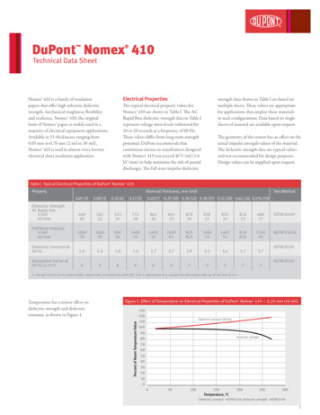
Robert Hydraulique Inc.Maintenance ManualTest Preparation:Bring the vehicle into a dry location andallow the fibreglass section to dry thoroughly.We recommend allowing the equipment to dryfor 12 to 24 hours prior to testing. Tip: Placethe aerial device in front of a heating unit witha vent and tip the bucket fully forward toallow the hot air to dry the fibreglass interior.Note: Contrary to popular belief, dielectrictests must be performed on components thatare completely dry. Operating the equipmentin rain or other damp conditions presents noadditional hazards. The tests are extreme, however, and all conditions must be ideal toensure the validity of results.The equipment must be washed prior to testing. If the equipment is not washed, the testcan only serve as an operational spot check, providing no opportunity to monitor changesin the quality of the insulating materials. Tests performed without a prior cleaning haveno real value in regard to the intended objective. At the same time, we believe that anannual washing is an efficient maintenance procedure to keep the aerial device in properoperating condition. The booms must be kept free of foreign matter such as paint (otherthan that of the manufacturer, Robert Hydraulique Inc.) or other greasy or adhesivesubstances, unless approved by Robert Hydraulique Inc.Pay particular attention to the cleaning products used, since some are highly conductive.Use water- or ammonia-based products or volatile cleaning solutions.Ensure that your test area is clear of all metal parts and other conductive elements (e.g.,telephone wire within a wall). Allow for a clearance of at least 8 feet (2.44 meters)around the tested equipment and be sure to include the building’s structure (such as theceiling) in your clearance calculations.Also ensure that no vehicle part or accessory, aside from the tires, is in contact with theground.Page 32
Robert Hydraulique Inc.Maintenance ManualTest Criteria:Note: In accordance with the following table, excerpted from CSA Standard C225-00,RH aerial ladders are classified as Category C. The duration of the direct current (DC)test is thus 3 minutes at 56 kV, and the leakage current shall not exceed 56 µA (microamperes). If you perform the test with alternating current (AC), duration is one minute at40 kV, and the leakage current shall not exceed 40 µA.Reference: C225-00 (page 32), published in 2001 by the Canadian Standardization Association.Page 33
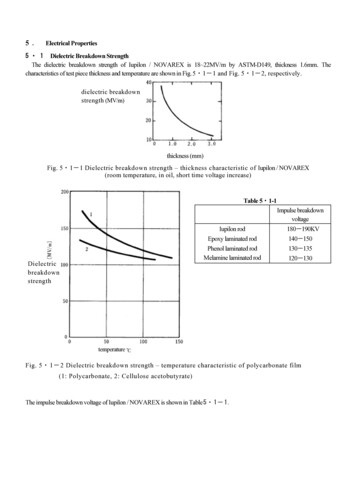
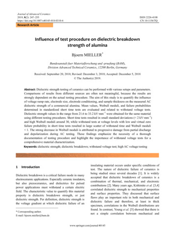
Robert Hydraulique Inc.Maintenance ManualConnecting the Equipment:Establish a safety perimeter around the equipment to be tested(aerial ladder and vehicle).The control station shall be a minimum of 10 feet (3.05 meters) away to properly protectthe operator. (Note: These measures pertain to the dielectric testing machine belonging toRobert Hydraulique Inc. Please read the operator’s manual provided with your dielectrictest equipment to familiarize yourself with the manufacturer’s safety recommendations,which shall always take priority over this general procedure.)Prior to connecting any equipment, ensure that all the controls are in the “OFF” position.Several models of dielectric testing devices have a fuse that operators can remove; it isalways safer for them to have it in their possession so as to avoid any shock hazard whenconnecting the equipment.Ensure that the vehicle is turned off (key in “OFF” position).Connect your generator to the safety ring located near the bucket.Then connect your load return to the last rung of the aluminumsection (see diagram). Ensure that your pliers (or similar) arecentered on the rung and pointed upward so there is the leastamount of interference when reading the leakage current.Install grounds on the dielectric equipment. Do not place grounds on the vehicle or theladder.Ensure that no one is inside the demarcated safety area.Begin the test, adhering to the test criteria listed on the preceding page.Page 34
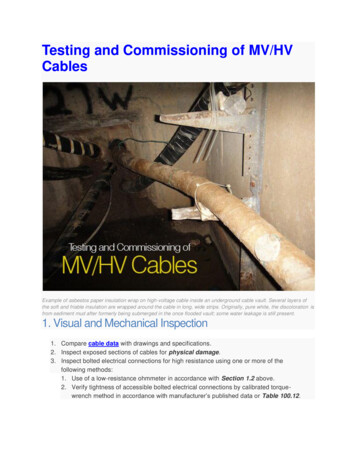
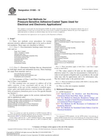
Robert Hydraulique Inc.Maintenance ManualWiring diagram:Page 35
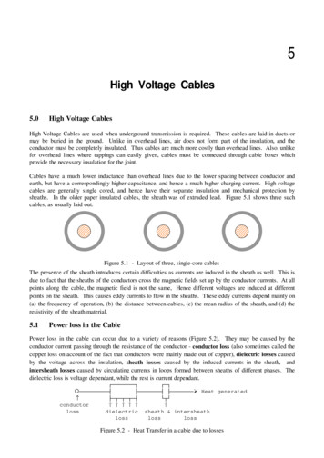
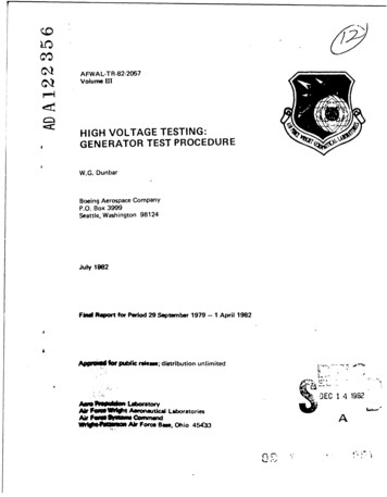
Robert Hydraulique Inc.Maintenance ManualFor results analysis:Electrical conversion tableMicroampere (uA):Milliampere (mA):Ampere (A):****Example of a control panel for dielectric testing****Once the voltage is totally shut off, remove any residualelectric charge using a pole with a metallic tip connectedto the building (ground). Touch any elements that may beelectrically charged, such as the HIPOT of your dielectrictest device, the levelling cylinder, the bucket mountingbracket, and the aluminum sections.Always maintain clearance when returning the pole to the grounding point.Do not forget to have your equipment calibrated annually (or according to themanufacturer’s recommendations) by a certified company.Page 36110-310-6
Robert Hydraulique Inc.Maintenance ManualReport recommended by the manufacturer:Page 37
Robert Hydraulique Inc.Maintenance ManualProcedure to Replace Rollers with BlocksReplacing K225A-V01 rollers with 226-00-V01 blocks2nd section, front end:1. Extend the aerial device to its maximum length.2. Unbolt bracket 216-00-V02 on the side that needs the roller replaced.3. Remove the 4 bolts from bracket 235-00-V01.4. Slide bracket 235-00-V01 with the roller towards the front of the aerial device.5. Replace roller K225A-V01 with block 226-00-V01.6. Re-install bracket 235-00-V01 with the recess pointed downward.7. Torque the 4 bolts down to 44 ft-lb. (Tighten the 2 bottom bolts to the base plateand apply Locktite; please note that these bolts do not have a washer or lockwasher.)8. Bolt on bracket 216-00-V02.Page 38
Robert Hydraulique Inc.Maintenance ManualReplacing K225A-V01 rollers with 226-00-V01 blocks2nd section, rear end:1. Remove the 6 bolts on the side that needs the rollers replaced.2. Slide bracket 225-00-V01 with the rollers to the rear.3. Replace the rollers with blocks 226-00-V01.4. Re-install bracket 225-00-V01 with the recess pointed downward.5. Torque the 6 bolts down to 44 ft-lb.Page 39
Robert Hydraulique Inc.Maintenance ManualReplacing K225A-V01 rollers with 226-00-V01 blocks3rd section, front end:1. Extend the aerial device to its maximum length.2. Unbolt bracket 216-00-V02 on the side that needs the roller replaced.3. Remove the 4 bolts from bracket 235-00-V01.4. Slide bracket 235-00-V01 with the roller to release it from the section.5. Replace the roller with block 226-00-V01.6. Re-install bracket 235-00-V01 with the recess pointed downward.7. Torque the 4 bolts down to 44 ft-lb.8. Re-install bracket 216-00-V02 and bolt it on.Page 40
Robert Hydraulique Inc.Maintenance ManualReplacing K225A-V01 rollers with 226-00-V01 blocks3rd section, rear end:1. Remove the 4 bolts from bracket 235-00-V01.2. Remove the bracket with the roller toward the rear end of the ladder.3. Replace roller K225A-V01 with block 226-00-V01.4. Re-install the bracket with the recess pointed downward.5. Torque the 4 bolts down to 44 ft-lb.Page 41
Robert Hydraulique Inc.Maintenance ManualOMNEX Programming Procedure Turn the transmitter “OFF” and turn the receiver “ON”. 3 lights will come on: Press and hold the transmitter’s “ON” button, then simultaneously press and holdthe red “E-STOP” button and the green button. The yellow light will come on and flash slowly. Press and hold the blue “Setup” button on the receiver; a yellow light will flashslowly. Continue to hold it down (approx. 5 seconds). Do not hold for more than 30 seconds, otherwise the procedure must be repeated. Press and release the green “Power” button on the transmitter. This will initiatethe download. On the transmitter, a red light will come on and change to yellow.On the receiver, the “Link” light will come on and flash. When the download iscompleted, the red battery lights and yellow (active) light will go out. The “Link”light on the receiver will go out and the green “Status” light will begin to flash. Turn off the receiver and turn it back on, then repeat with the transmitter.- “Status” light- “E-STOP” light- Center lightPage 42
Robert Hydraulique Inc.Maintenance ManualProcedure for Reprogramming the OMNEXAuto shut down1. Disconnect and reconnect the 5-pin plug on your receiver to ensure that thesystem is fully turned off.2. Proceed in the following sequence: Press and hold the red button Press and hold the green button Release the red button Release the green buttonAt this point, the light to the right of the green button (based onpositioning depicted below) should flash.3.GREEN13524678RED1Enter the following number sequence: 3 – 1 – 4 – 2; then press on the GREENbutton.When completed, the 2 lights should flash.5. Continue with the following number sequence: 5 – 1 – 8 – 8 – 8 – 8 – 8 – 8 – 8 –8; then press on the GREEN button. At this time, the lights should come on for a fewseconds before going out.6. The auto-off, on your controller is now re-activated.Page 43
Robert Hydraulique Inc.Maintenance ManualCylinder Valve Adjustment ProcedureElevation cylinder: To adjust the valve on the elevation cylinder, the aerial ladder must befully extended. Raise the aerial device to 45 degrees. To tighten the valve, loosen the Allen screw. To loosen the valve, tighten the Allen screw.Loosen the valve (tighten the screw) until the aerial device slowly lowersby itself and re-tighten the valve (loosen the screw) until the aerial devicestops moving. Then tighten the valve (loosen the screw) by 1¼ turns andthe valve will be adjusted. Secure the Allen screw with the nut.Extension cylinder:Loosen the valve (tighten the Allen screw) fully and re-tighten the valve by 1turn (loosen the Allen screw).Levelling cylinder:Adjust the valve to the center position, or 2½ turns in one direction or the other;tighten or loosen completely.Page 44
Robert Hydraulique Inc.Maintenance ManualStability Test for RH Aerial DeviceThis procedure is based on standard CSA C225-00. The most current standards alwayshave priority over the following procedure.Pre-Test Preparation: Remove all items that are not permanently installed from the vehicle. Enter general vehicle and equipment information on the RH # FORM0017 form. To do so, you will need to measure, weigh and compare themanufacturer’s tolerances with your results. Ensure that the tire pressure corresponds exactly to the pressurerecommended by the vehicle manufacturer. Pressure that is too high or toolow will skew test results. Be sure to check and adjust the pressureimmediately prior to performing the stability test to avoid temperaturedeviations that may also cause changes in the tire pressure.Stability Test: Position vehicle on a level surface (e.g., parking lot). The area must befree of any objects that could interfere with the test. Establish a safety perimeter. Straighten vehicle tires. Ensure that handbrake remains fully engaged. Chock the wheels. The aerial device must be perpendicular to the truck and fully extended.The ladder must be parallel to the ground. Using a chain, attach loads to the last rung of the ladder (zinc-platedbucket support), as indicated in the “Table of Equivalent Loads forStability Test Purposes”. Ensure that the chains do not pinch the hydraulichoses. Stand behind the vehicle in order to monitor the tires on the side oppositethe weight, as well as the aerial device.Page 45
Robert Hydraulique Inc. Maintenance ManualRaise the load approximately 4-5 inches (10 to 12 cm) above the ground.Remember that the ladder must always remain parallel to the ground.If the aerial device has difficulty in lifting the load, you can either retractthe ladder slightly to give it greater force or adjust the Sun cartridge (valveblock) located at the base, using an Allen wrench. Rotate the unit to 45 degrees from the rear of the vehicle and then rotateback to 45 degrees from the front of the vehicle. Perform these operationsas smoothly as possible. Return to the starting point.The vehicle must not lose its equilibrium point (stability). Thus, the wheels may lift offthe ground but not more. If the weights touch the ground and the vehicle no longertouches the ground, the vehicle has failed the test.You must conduct this test on each side of the vehicle, at a -5 degree angle to the axle andon a horizontal surface. A lifting ring test (647 lbs on a horizontal surface) is alsorequired.When performing the test, we recommend you also inspect the vehicle and equipment inorder to identify any discrepancies.Place a sticker on the bucket, indicating the certified weight.This test is required whenever there is a change of vehicle and/or a modification is made that could havean impact on stability.Page 46
Robert Hydraulique Inc.Maintenance ManualReport recommended by manufacturer:Page 47
Robert Hydraulique Inc.Maintenance ManualBucket Heater Installation and Operating InstructionsInstallation:Before installing the heater, you must check it as described below. Once the heater isinstalled in the bucket, repeat the procedure to check for proper installation andoperation.1. Turn switch to “Off” position (see Diagram 1).2. Plug heater into a 115-volt AC outlet.3. Turn switch to “On” position (opposite to “Off” position, see Diagram 1).4. The motor should start working and air should come out of the unit. If no aircomes out, check that there is no foreign body impeding the fan’s rotation. Turnswitch to “Off” position, turn the fan by hand to ensure that it turns freely andthen repeat step 4.If warm air blows out, you are now ready to install the heater. Unplug it from the 115volt AC outlet. Install the heater with the safety screen facing the bottom of the bucket.ONCE THE UNIT IS INSTALLED, REPEAT STEPS 1-4 LISTED ABOVE.*** NOTE*** The heater is equipped with a temperature sensor that turns the heatingelement off if the unit overheats. This happens only if there is malfunction or if theairflow is blocked. Remove the obstructing item or replace the defective part. To reset thesensor to 0, remove the heater from the bucket, remove the air deflector panel from theback of the heater and press on the little red reset button (see Diagram 2 below). Theheater will not blow out hot air if inflow air is warmer than 90 F (32 C).DIAGRAM #1DIAGRAM #2Page 48
Robert Hydraulique Inc.Maintenance ManualOperation:1. Turn switch to “Off” position (see Diagram 1).2. Plug heater into a 115-volt AC outlet.3. Turn switch to “On” position (opposite from “off” position, see Diagram 1).4. The motor should start working and air should come out of the unit. If air doesnot come out, ensure that the problem is not due to an object obstructing the fan.Place the switch in the “Off” position, and turn the fan by hand to see if it turnsfreely and repeat step 4.5. When the heater is no longer needed, place the switch in the “Off” position.If warm air blows out, you are now ready to install the heater. Unplug it from the 115volt AC outlet. Install the heater with the safety screen facing the bottom of the bucket.ONCE THE UNIT IS INSTALLED, REPEAT STEPS 1-4 LISTED ABOVE.*** NOTE*** The heater is equipped with a temperature sensor that turns the heatingelement off if the unit overheats. This happens only if there is malfunction or if theairflow is blocked. Remove the obstructing item or replace the defective part. To reset thesensor to 0, remove the heater from the bucket, remove the air deflector panel from theback of the heater and press on the little red reset button (see Diagram 2 below). Theheater will not blow out hot air if inflow air is warmer than 90 F (32 C).Page 49
Robert Hydraulique Inc.Maintenance ManualCentralizer Adjustment Procedure1Raise the aerial device to access the slewing ring.2Give a first command input to the left (approx. 1 ft.) and return to center. Checkwhere the aerial device comes to a stop relative to the slewing ring.3Carry out the same command, but this time to the right.4If the aerial device stops at the same distance on each side of the slewing ring, youneed to adjust the central positioning micro switch.* If the aerial device does not stop at an equal distance on each side with respect tothe slewing ring, unscrew the 2 screws that hold the aluminum plate located underthe centralizer’s upper base.* Next, move the plate toward the outside to shift the aerial device to the right, orpush it toward the inside to shift the aerial device to the left.5Turn the aerial device to the right to free the centralizer from the base.6Remove the 4 Torx drive screws on the top of the central positioning micro-switch.You will find a torque screw inside.7Turn it counter-clockwise to bring the ladder toward the center of the slewing ring,or turn it clockwise to move it away from the center. *Note: Turn the screw ¼rotation at a time in order to find the center.8Once centering is completed, put the cover back in place and reinstall the 4 screws.Page 50
Robert Hydraulique Inc.Maintenance ManualChecking Valves on Power UnitThe position of the valves on the HP02 power unit is depicted below.The positioning of the hydraulic hoses is depicted below; each number corresponds to thenumber on the hoses.Page 51
Robert Hydraulique Inc.Maintenance ManualHydraulic Fluid Change ProcedureModels RH35 to RH50D equipped with HP02 power unit1Position the aerial device -5 degrees to the right (orthe left) of the vehicle.2Attach bucket using a strap.3Remove the cotter pin and the pin on the bucketlevelling cylinder.4Activate the bucket levelling function to retract thecylinder.5Disconnect the filterinlet hose, then turn thehose down to recoverthe old hydraulic fluid.6Fully extend the ladder.Page 52
Robert Hydraulique Inc.Maintenance Manual7Connect the 2 bucket hoses.8Empty the reservoir by activating the “level up” function of the bucket levellingsystem several times using the lower controls.9Fill the reservoir with HL17106 hydraulic fluid.10 Activate the bucket’s “level up” function three times using the lower controls. Thehydraulic pump will stop automatically.11 Check the reservoir to ensure the hydraulic fluid is at the proper level.12 Retract the aerial device as far as possible.13 Raise as high as possible.14 Change the hydraulic fluid filter.15 Position aerial device at -5 degrees.16 Check hydraulic fluid level.17 Reconnect hoseson the bucketlevellingcylinder.Page 53
Robert Hydraulique Inc.Maintenance Manual18 To bleed the levelling cylinder, open the hosefitting on the cylinder and activate the “level up”function 3 times using the lower controls. Wait forthe pump to stop automatically. Repeat thisfunction while simultaneously closing the fitting.19 Open the hose fitting on the cylinder and activatethe “level down” function three times using thelower controls. Wait for the pump to stopautomatically. Repeat this function whilesimultaneously closing the fitting.20 Reposition cylinder on bucket. Replace the pin and cotter pin.21 Note: be sure to actuate the “level up” function before removing strap.22 Check the hydraulic fluid level one last time.Page 54
Robert Hydraulique Inc.Maintenance ManualSteel Cable Replacement ProcedureRH35 to RH50D models (at least every 3 years!!!)For an optimum efficiency, grease your cables regularly. Here are effective products suggested by themanufacturer of cables: Swepco 803, WRL 34041 of Jet Lube and CD 1000 of Prolab.1. Place ladder in horizontal position.2. Remove the 2 bolts that fasten the Catrac holder tothe cable support.3. Remove the 4 Stover nuts of the cables (2 on eachside). * Be sure to count the number of threadsextending past the end of the Stover nuts in order toinstall new cables with the same tension.*4. Remove the 8 bolts on the 2nd rung of the 3rd section.5. Remove the supports that secure the cables to thesection.6. Unbolt the side rollers of the second section.7. Unbolt the 4 pulleys located at the 4 extremities ofthe 2nd section.Page 55
Robert Hydraulique Inc.Maintenance Manual8. Remove the cables from the aerial device.9. Install the new cables between the first andsecond sections, and between the second andthird sections.10. Thread cable ends through the eyelets of thecable supports. *Turn eyelets up and wait beforeadjusting them.11. Install the cables in their support on the 2nd rung of the 3rd section.12. Install the 4 pulleys and their accessories, andfasten with bolts. *To adjust the cables, tightenthe Stover nuts based on thread count prior todisassembly. (See step 3)13. Install the Catrac holder on the cable support.14. Bolt the side rollers of the second section back on. Check that there is an equal spacebetween the sections.15. Tighten the bolts back to 44 in.-lb. of torque.Note:If the lower support bolt on the second rung of the 3rd section is ablack torque bolt (see photo), replace it with a 3/8 x 2 in., grade 8bolt. Do not use a flat washer or lock washer. Instead use 2 dropsof red Threadlocker.Page 56
Robert Hydraulique Inc.Maintenance ManualLowering RH Aerial Device in Case of a Malfunction(Engine is Operable)Situation: The aerial device doesn’t lower but the engine is operable.1. Ignition on.2. Engage the parking brake.3. Use a screwdriver to press on the metal tip on top of the valve, depending on thefunctions desired, or beneath it, as required.If the solenoid is defective, bypass the solenoid to the motor. Then repeat steps 1 to 3.Once the ladder is in place, you can go to the service centre nearest you!Lowering RH Aerial Device in Case of a Malfunction(Engine is Inoperable)Using a 7/8 ratchet wrench, go to the end of the rotation motor and turn the worm screw.This will cause the ladder to rotate; turn the worm screw until the aerial device iscentered with the slewing ring.Then go the base of the extension cylinder where you will see a holding valve. Using a9/16 wrench and an Allen wrench, slowly loosen the pressure valve. This will cause theladder to retract by means of gravity. If for some reason, you wish to stop lowering theladder, you just have to tighten the valve. Do not get caught between two ladder rungsduring this procedure.Lastly, go to the base of the ladder where the elevation cylinder is located. Perform thesame procedures with this cylinder’s holding valve. Prior to proceeding, ensure that theladder is properly centered with the slewing ring since this can only be done once.Once the ladder is properly in position, you can proceed to the service center nearest you!Crack in weldingOn the aerial ladder, if a crak appears in a welding, please directly contact themanufacturer to know if it is about a critical welding.Page 57
Robert Hydraulique Inc.Maintenance ManualELECTRICAL PROBLEMS (Model:SOURCEVehicle battery has low voltageRH35 to RH50D)DESCRIPTIONNot enough voltage to charge:1. The electrical motor2. The electrical motor relay3. The coils of the hydraulic directionalvalves4. The main panelFaulty contact on the positive and negative No power / intermittent power for:terminals of the vehicle battery.1. Main panel2. Electrical motorMain circuit fuse blownInsufficient power supply for :1. Main panel2. Electrical motorPoor contact on the electrical motor’s relay No power / intermittent power to:terminals1. Main panel2. Electrical motorELECTRICAL PROBLEMS (Model: RH35 to RH50D)DESCRIPTION OF PROBLEMNo command works, regardless ofcontrol box used.POSSIBLE CAUSESIf there is no power supply to the main panel,either:1. Vehicle key is not in “ignition” position2. Parking brake is not engaged3. Main fuse is blown4. There is a bad contact on the vehicle’s batteryterminals5. Faulty power supply connection to the mainpanel6. Vehicle battery has low voltage7. The main panel’s circuit board is defectiveIf power is being supplied to the main panel :1. LampPage 58
Robert Hydraulique Inc.Maintenance ManualDiagram of Printed Circuit BoardPage 59(Model: ES03-1)
Robert Hydraulique Inc.Maintenance ManualElectrical System(Model: RH35 to RH50D)Page 60
Robert Hydraulique Inc.Maintenance ManualPage 61
Robert Hydraulique Inc.Maintenance ManualLower controlsUpper controlsJ2Wire #ColorJ3Function1RedPositive 1-32Black3Red / black4Brown / blackElevation5BrownLowering6Yellow / black7Yellow8Blue / blackExtension9BlueRetraction10Orange / black11Orange12Black / redNeutral 2Positive return 4-5LeftRightLevelling (top)Levelling (bottom)Safety wire #9The “blue / red” and “orange / red” wires are not used.Page 62
Robert Hydraulique Inc.Maintenance ManualHydraulic Diagrams (Model:Page 63RH35 to RH50D)
Robert Hydraulique Inc.Maintenance ManualPage 64
Procedure: Dielectric Strength Test Dielectric tests are used in the industry to inspect a wide variety of products, devices, and . **** Example of a control panel for dielectric testing **** Once the voltage is totally shut off, remove any residual electric charge using a pole with a metallic tip connected to the building (ground). Touch any .