Transcription
www.orioncontrols.comVCM - ControllerTechnical GuideVCM Controller Code: SS1016Requires System Manager Code: SS1010 Version 3.0 and upRequires Service Tool Code: SS1009 Version 3.0 and up
Table Of ContentsController Overview . 4Features . 4Applications . 4Controller Installation & Wiring . 8General . 10Controller Mounting . 10Important Wiring Considerations . 10Expansion Board Installation & Wiring . 11Jumper Settings . 11Wiring Considerations . 12Input/Output Wiring Details . 14Space Temperature Sensor . 14Remote SAT Reset Signal . 14Supply & Return Temperature Sensor . 15Outdoor Air Temperature Sensor . 17Economizer Damper Actuator . 18Suction Pressure Transducer . 19Supply Fan VFD Signal Or Zoning Bypass Damper Actuator . 21Binary Inputs Wiring . 22Outdoor Air Humidity Sensor . 23Indoor Wall Mounted Humidity Sensor . 24Return Air Mounted Humidity Sensor . 25Building Pressure Sensor Wiring . 26Building Pressure ControlOutput Wiring . 27CO2 Sensor Wiring . 28Modulating Heating Device Wiring . 29Modulating Cooling Device Wiring . 30Return Air Bypass Wiring . 31Start-up & Commissioning . 32Controller Addressing . 32Power Wiring . 32Initialization: . 33Operating Summary . 33Programming The Controller . 33Inputs & Outputs . 34VCM Controller . 34OE354 (4) Analog Input(1) Analog Output Expansion Board . 35OE355 (4) Analog OutputExpansion Board . 35OE357 (4) Relay Expansion Boards . 35OE356 Binary Expansion Board #1 . 36OE356 Binary Expansion Board #2 . 36www.orioncontrols.comWattMaster Controls Inc.8500 NW River Park Drive · Parkville , MO 64152Toll Free Phone: 866-918-1100PH: (816) 505-1100 · FAX: (816) 505-1101 · E-mail: mail@wattmaster.comVisit our web site at www.orioncontrols.comForm: OR-VCM-TGD-01A Copyright 2005 WattMaster Controls, Inc.AAON is a registered trademark of AAON, Inc., Tulsa, OK.WattMaster Controls, Inc. assumes no responsibility for errors, or omissions.This document is subject to change without notice.
Technical GuideSequence Of Operations . 37Occupied/UnoccupiedMode of Operation . 37HVAC Modes of Operation . 37Vent Mode Operation . 37Cooling Mode Operation . 37Dehumidification Mode . 39Remote Forced Dehumidification . 40Return Air Bypass Damper Control . 40Heating Mode Operation . 40Warm-up Mode Operation . 42Off Mode . 42Remote Control of HVAC Mode . 42Supply Air TemperatureSetpoint Reset . 42Supply Fan Control . 43Duct Static Pressure Control . 43Building Pressure Control . 43IAQ (CO2) Operation . 44Pre-heater Operation . 44Outdoor Air Lockouts . 44Supply Air Cutoffs . 44Scheduling . 44Internal Trend Logging . 45Force Modes or Overrides . 45VAV/Zone Box Compatibility . 46VAV/Zone System . 46Zoning System . 46Troubleshooting . 47Using LEDs To Verify Operation . 47Appendix . 48Diagnostic LEDs Operation . 48System Configuration Options . 4910 kOhm Type III Temperature Sensor Testing . 53OE265 RH Sensor Testing . 54OE271 Pressure Sensor Testing . 55OE258 Pressure Sensor Testing . 55OE275 Suction Pressure Transducer Testing . 56Notes: . 57VCM Controller3
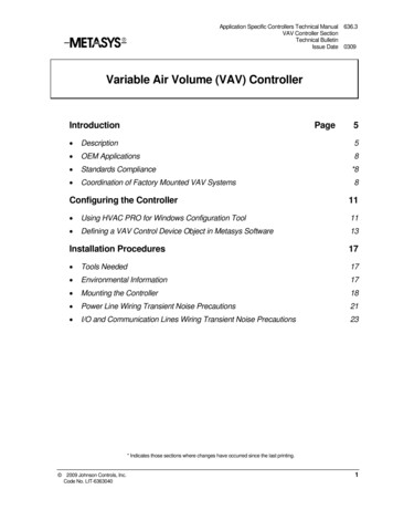
Technical GuideController OverviewFeaturesThe VCM Controller Board is designed with 7 analog inputs, 2 analogoutputs and 5 relay outputs. The controllers input and output capabilities can be expanded by use of either 2 slot or 4 slot expansion boardsthat plug into the VCM Controller by means of a modular cable. TheVCM Controller can be configured for control of VAV Units (with orwithout VAV/Zone Controllers), Constant Volume Units and Make-upAir Units. Features include the following: Up to a Combined Total of 20 Stages of Heating & Cooling Modulating Heating Output (Hot Water Valve, Steam Valve,SCR Electric Heat Control) Full Integration with the AAON Modulating Cooling Output (Digital Compressor or ChilledWater Valve Control)MODGAS II Modulating Natural Gas Controller4 Full Integration with the AAON MHGRV II ModulatingHot Gas Reheat Controller Configurable for Air to Air Heat Pump Applications Configurable for PAC and DPAC ApplicationsAdvanced Dehumidification CapabilitiesPrimary/Secondary Heating ControlAutomatic Supply Air ResetSelectable Control SensorFan Proving InterlockDirty Filter AlarmSmoke Detector InputDrybulb/Wetbulb Control of Economizer OperationBuilding Pressure ControlRemote Override CapabilitiesI.A.Q. Economizer Reset7 Day, 2 Event per Day Scheduling14 Holiday Event SchedulingOptimal Start SchedulingTrend Logging CapabilityStatic Pressure Control For Filter Loading ApplicationsAccepts Remote HVAC Mode Selection Via ContactClosure On Expansion Input BoardMost common HVAC unit control applications can be configured usingonly the VCM Controller board. If the application requires more inputsand/or outputs, optional expansion boards are available to provide foradditional analog, binary or digital inputs and outputs as required. Theseexpansion boards are installed on either a 2 slot or 4 slot expansion baseboard that connects to the VCM Controller board via a modular cableconnection.The available expansion board configurations allow for (8) additionalbinary inputs, 4 additional analog inputs, 1 additional analog output,and up to 16 additional binary (relay) outputs. The various expansionboards connect to the 2 slot or 4 slot expansion base boards. Jumperslocated on the base boards near each expansion board socket must beset according to the board type installed on that socket.ApplicationsVariable Air Volume UnitThe VCM can be configured to control a VFD Supply Fan for DuctStatic Pressure control. If the unit is not equipped with a VFD, but DuctStatic Pressure control is needed, a modulating Zoning Bypass Dampercan be controlled by the VCM.VAV units are typically designed for occupied Cooling with MorningWarm-up Heating. This option is available with the VCM. The VCMcan also be used for a Zoning System that needs Duct Static Pressurecontrol and Occupied Cooling and Heating. The VCM also has the ability to be configured for Duct Static Pressure Control by controlling theSupply Fan VFD for the purpose of maintaining proper Duct StaticPressure in response to varying filter loading conditions.The VCM allows Dehumidification Priority on a VAV unit. This couldbe useful on a building with very low internal sensible load, but has ahigh internal and/or external latent load. During VAV Dehumidificationthe VCM activates Cooling based on the Evaporator Coil Temperatureand activates Modulating Hot Gas Reheat to warm the Supply Air Temperature to the Active Supply Air Temperature Setpoint.Constant Air Volume UnitThe VCM can be configured to activate a Constant Volume SupplyFan. In most cases, this is a very basic unit with Space Temperaturecontrol. The VCM can be used for kitchen, restaurant or lab environments that are 100% Outdoor Air part of the time and return air part ofthe time. The Hood On input allows the VCM to know when to switchto 100% Outdoor Air control based on an exhaust hood activating. TheVCM requires Outdoor and Indoor Air Temperature Sensors to accomplish this application.Make-up Air UnitThe VCM can be configured for 100% Outdoor Air control for Makeup Air. All HVAC Modes are determined from the Outdoor Air Sensors.The Outdoor Air Volume must always be at least 50% or higher to beconfigured for Outdoor Air control.VCM Controller
Technical GuideAir to Air Heat Pump UnitThe VCM can be configured to control an Air to Air Heat Pump. Thecompressors are used for both Heating and Cooling. With the VCMcontroller the Reversing Valve is activated during Heating operation asthe default because AAON units are typically built to fail to Coolingoperation. The Reversing Valve can be configured to activate duringCooling operation for equipment that is built to fail to Heating operation.Auxiliary Heating Stages are configured as Heat Relays and are used tosupplement the Compressor Heating Stages. If the unit is not equippedwith Auxiliary Heating Stages, Heating Relays do not need to be configured in order for the unit to provide Heating. Auxiliary Heating canalso be Modulating heat in the form of SCR Electric, Hot Water orSteam.The Cooling and Dehumidification Modes operate in the same manneras described under the Cooling and Dehumidification titled sections ofthis manual. In the Heating Mode, the VCM activates the ReversingValve and stages compressors to provide Heating if the Outdoor AirTemperature is above the OAT Cooling Lockout Setpoint. The compressor heating stages are activated as needed to achieve the ActiveSupply Air Setpoint. Staged or Modulating Auxiliary Heat can be activated to supplement Compressor Heating in order to achieve the ActiveSupply Air Setpoint if the Outdoor Air Temperature is below the OATHeating Lockout Setpoint. If the Outdoor Air Temperature is below theOAT Cooling Lockout Setpoint, only Auxiliary Heating will occur. Ifthe Outdoor Air Temperature is above the OAT Heating Lockout, onlyCompressor Heating will occur.PAC (Precision Air Control)This control scheme can only be used on Constant Volume HVACunits that are equipped with a Return Air Bypass Damper and use aSpace Temperature Sensor as the Controlling Sensor.For PAC configured units, the Return Air Bypass Damper is only usedduring the Dehumidification Mode. When the VCM controller is in Dehumidification Mode, the Return Air Bypass Damper will modulateopen as the Space Temperature falls below the Cooling Setpoint. Modulation of the Return Air Bypass Damper is controlled using a proportional range from 0% (when the Space Temperature is equal to the Cooling Setpoint), up to 100% (when the Space Temperature falls to thehalfway point between the Cooling and Heating Setpoints). A separate,Return Air Damper Actuator will modulate the Return Air Damperslightly further towards its closed position as the Return Air BypassDamper opens. This is to ensure that enough Return Air is bypassedaround the Evaporator Coil through the Return Air Bypass Damper toraise its temperature. The rate which the Return Air Damper closes whilethe Return Air Bypass Damper is open is user adjustable.DPAC – Digital Precision Air ControlThis control scheme can only be used on Constant Volume HVAC unitsthat are equipped with a Return Air Bypass Damper, a Digital Compressor and use a Space Temperature Sensor as the Controlling Sensor.The DPAC control scheme provides improved moisture removal capabilities over the PAC control scheme and provides for tighter temperature control by combining a Digital Compressor with the Return AirBypass Damper. See the Cooling Mode section of this manual for detailed Digital Compressor operation. See the PAC Control previouslydescribed in this section for detailed Return Air Bypass Damper operation.The Digital Compressor is used during both Cooling and Dehumidification Modes. The Return Air Bypass Damper is used only during theDehumidification Mode.PAC Control provides improved moisture removal capabilities whileutilizing internal space loads for reheat by redirecting the Return Airpath from the upstream side of the DX Evaporator Coil to the downstream side of the coil.VCM Controller5
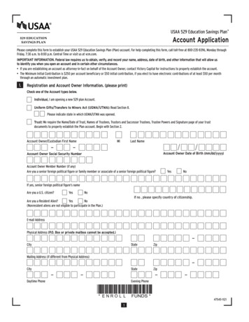
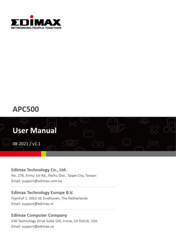
Technical GuideController Overview.20 Dia.Typ. of MV2TSHLDRLY2V3RU5PALRS-485COMMEPROMRAMRLY3TUC-5R PLUSHH(1 MEG)YS101816 REV. 2RN3U6D41RN2C2X1V4EWDOGRV1VREF 1X2C110-5VDCGND C10GNDAOUT1 C12AOUT2AIN7GND TOKENNETWORKD10RN5RN41R7 1VTEST POINTCOM4-5RLY4P1 7.3”COM1-3D3CX5LD6T'STATVR1VR26.7”Figure 1: VCM Controller Dimensions6VCM Controller
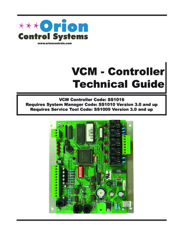
K1K2K3K4OMRONG5L-114P-PS24VDCCONTACT:UL 5ACTR20R3R2R1C3LM358T LHA PHILIPSANI DLM358NR6R5R4C4C1CX3P1MCMC7805ACT 7824CTD3U1P1CX1TB1LM358R1C2TDA8444PU3PCF8591P4 ANALOG IN MOD. I/O 114P-PS24VDCCONTACT:UL NV1R54RLY IO BD.G5L-114P-PS24VDCCONTACT:UL 5A250VACJP4R18BIN 1BIN 2BIN 3BIN 4D1R6D2R8R7D3D4R9PU1PU2PU3C5C1PU4C24 DIG. IN MOD. I/O BD.YS101788R12OMRONP4R16VR14 SLOT MODULAR I/O BD.YS101782COMG5L-114P-PS24VDCCONTACT:UL 5A250VACJP3C7P3R7 R8 R9C6VR8K1JP2R4 R5 R6VR7AOUT1AOUT2AOUT4AOUT3GND4 AOUT MOD. I/O 5CX2VR4P2U2C4VR6C5C3VR5OE352 2 Slot Expansion Base 1R14R13C1D2D1R19VR3CX3VR2P1D1D2 R7 R8C1CX3VR4MC7824CTR15R17R9R11R13VR3MC7824CTPJ1PJ2 24VDC-OUTLD1PWR24VAC-INGNDGNDC8PJ1PJ2 7”1.67”OE3574 Relay OutputExpansion BoardOE3564 Binary InputExpansion BoardOE3554 Analog OutputExpansion BoardOE3544 Analog Input 1 AnalogOutput Expansion Board5.964.737VCM Controller0.282.124.24” 4.00”4.24”Q1CX24.00”D5R10LM358Technical Guide4.004.240.282.12OE353 4 Slot Expansion Base Board4.24Figure 2: Expansion Base Boards DimensionsFigure 3: Expansion Boards DimensionsR14D32 SLOT MODULAR I/OYS101780TB1U2P1
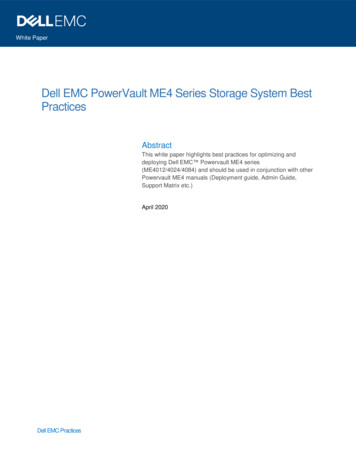
Technical GuideController Installation & WiringTypicalPin tionsLoop ConnectionV2TSHLDRLY2V3RU5PALRS-485COMMRLY3HH(1 MEG)YS101816 REV. 2U6D4TUC-5R PLUSRN21C2TEST 1C13R15U12CX14C14R19TB4C15D19GNDD16R22Expansion Board(Modular Connection)C1924 VACPower s SwitchSC1U13AOUT2AIN7GND C17Duct Static Pressure Sensor(AIN6 Modular D C10GNDAOUT1 D6PU2D10RN5RN41R7 VDCTB3V5RLY5C3R28INPUTSAIN1AIN2AIN3AIN4Relay OutputTerminal BlockV4EWDOGRV1VREF ADJTB2D5CX65.11VU7COM4-5RLY4P1 VREFR1Pull-up ResistorsFor Analog LD7PWRAnalog InputAnd OutputTerminal BlockCOM1-3D3CX5LD6RN3RS-485CommunicationsDriver ChipCommLEDPowerLEDDiagnosticBlink CodeLEDsMounting HoleTyp of 4PALChipD1Modular ServiceTool - Mini DinConnectorT'STATVR1VR2Real TimeClock ChipDigiSensor(Modular Connection)Figure 4: VCM Controller Component Locations8VCM Controller
AOUT2AIN7GND C17OE271S.P.TransducerSplice If Req’dFigure 5: VCM Controller Wiring DRESSPU1D6PU2EXPANSIONR26C1HHR28EWDOGC12RN5GND C10GNDAOUT1AIN5AIN1AIN2AIN3AIN4 VDCPJ1P15.11VTEST POINTRV1VREF ADJU7PRESSURESENSORTB3Connect FRP Tubing To High PressurePort (Bottom Tube) and Route To StaticPressure Pickup Probe Located In UnitDischarge. Leave Port Marked “Lo” OpenTo AtmosphereSee IndividualComponent WiringDiagrams For DetailedWiring Of Analog InputsAnd OutputsR1COMMRS-485U5 NETWORKADDCX2PHILIPS0-5VDC0-1VDCTB1COMMPJ2U2TUC-5R PLUSEPROMU3U14U10CX14U12CX10CX12CX6(1 MEG)YS101816 REV. X4VR2L1D13RLY1CX3X1R11V1V5V4TB2V3V2C9R6Line VoltageSize Transformer ForCorrect Total Load.VCM Controller 8 VAPower Consumption. IfEconomizer Option Is UsedThe Economizer ActuatorVA load Must Also BeConsidered When SizingThe Transformer.24VACGNDNote: A Total Of 20 Relays Are Available ByAdding Relay Expansion Boards. All ExpansionBoard Relay Outputs Are User Configurable AsListed Above.1 - Heating Stages2 - Cooling Stages3 - Warm-up Mode Command (VAV Boxes)4 - Reversing Valve (Air To Air Heat Pumps)5 - Reheat Control (Dehumidification)6 - Exhaust Fan Interlock7 - Preheater For Low Ambient Protection8 - Alarm9 - Override10 - Occupied11 - OA DamperRelay Output Dry ContactsR2 Thru R5 May Be User ConfiguredFor The Following:G - Fan ON/OFF OnlyR - 24VACNote:All Relay Outputs Are Normally OpenAnd Rated For 24 VAC Power Only.2 Amp Maximum Load.Warning:24 VAC Must Be Connected So That All GroundWires Remain Common. Failure To Do So WillResult In Damage To The 4-5R4R5R1R2R3COM1-3Connect ToExpansion BoardBase (When Used)Connection PortFor cal LoopRS-4859600 BaudC18CX8R10D16All Comm Loop Wiring IsStraight ThruT to T, R to R & SHLD to SHLDR27R7C19U11OE331-21-VCMVCM Controller BoardV6VCM ControllerPOWERC21MC34064A9936For Stand Alone Applications,Connect To System Manager. For NetworkApplications Connect To Next Controller And/OrMiniLink PD On Local Loop.Technical Guide9
Technical GuideController Installation & WiringGeneralCorrect wiring of the VCM controller is the most important factor inthe overall success of the controller installation process. In general mostVCM controllers are factory installed and wired at the AAON factory.It is also possible to purchase these controllers directly from WattMasterControls for installation in the field. Some of the following informationpertains to field wiring and may not apply to your installation since itwas pre-wired at the factory. However, in the unlikely event that troubleshooting of the controller is required, it is a good idea to be familiarwith the system wiring, no matter if it was factory or field wired.Controller MountingWarning: When using a single transformer to power morethan one controller or expansion board, the correctpolarity must always be maintained between theboards. Failure to observe correct polarity willresult in damage to the VCM controller andexpansion boards.Please carefully read and apply the following information when wiringthe VCM controller or the VCM Expansion Boards. See Figure 5 forVCM controller wiring diagram. See Figures 6, 7 and 8 for ExpansionBoard Wiring.When the controller is to be field mounted, it is important to mount thecontroller in a location that is free from extreme high or low temperatures, moisture dust and dirt. See Table 1 for a list of the required operating conditions for the VCM C
WattMaster Controls Inc. 8500 NW River Park Drive · Parkville , MO 64152 Toll Free Phone: 866-918-1100 PH: (816) 505-1100 · FAX: (816) 505-1101 · E-mail: mail@wattmaster.com Visit our web site at www.orioncontrols.com . this manual. In the Heating Mode, the VCM activates the Reversing