Transcription
APC500User Manual08-2021 / v1.1
CONTENTSI. Product Information . 1I-1.I-2.I-3.I-4.I-5.I-6.I-7.Package Contents .2System Requirements .3Hardware Overview .3LED Status .4Reset .4Console/HyperTerminal .5Safety Information .6II. Hardware Installation . 7II-1.II-2.Wall Mount .7Rack Mount .8III. Quick Setup . 9IV. Software Layout .16V. Features .23V-1.V-2.V-2-1.LOGIN, LOGOUT & RESTART .23DASHBOARD .25System Information -1-1.V-4-1-2.Devices Information.26Managed AP .27Managed AP Group.28Active Clients .29Active Users .30ZONE PLAN .31NMS MONITOR .33Access Point .33Managed AP .33Managed AP Group.35V-4-2.WLAN .37V-4-2-1.Active WLAN .37V-4-2-2.Active WLAN Group .38V-4-3.Clients .38V-4-3-1.Active Clients .38V-4-4.Users .39V-4-4-1.Active Users .39
V-4-4-2.Users Log .39V-4-5.Rogue Devices .40V-4-6.Information .41V-4-6-1.All Events/Activities .41V-4-6-2.Monitoring .42V-5.NMS Settings.43V-5-1.Access Point .43V-5-2.WLAN .56V-5-2-1.No Authentication .58V-5-2-2.WEP .58V-5-2-3.IEEE802.1x/EAP .59V-5-2-4.WPA-PSK .59V-5-2-5.WPA-EAP .60V-5-2-6.Additional Authentication .60V-5-3.RADIUS .62V-5-4.Access Control .68V-5-5.Guest Network .71V-5-6.Users .75V-5-7.Guest Portal .78V-5-7-1. Add/Edit Guest Portal .79V-5-7-1-1. Front Desk URL .80V-5-7-1-2. Front Desk Printout .82V-5-7-1-3. Guest Portal Type .83V-5-7-1-4. Guest Portal Customization .84V-5-8.Zone Edit .85V-5-9.Schedule.87V-5-10.Device Monitoring .89V-5-11.Firmware Upgrade .90V-5-12.Advanced .91V-5-12-1.System Security.91V-5-12-2.Date & Time .91V-6.Local Network .93V-6-1.Network Settings .93V-6-1-1.LAN-Side IP Address .93V-6-1-2.LAN Port Settings .96V-6-1-3.VLAN .97V-7.Local Settings .98V-7-1.System Settings .98V-7-1-1.System Information .98V-7-1-2.Log .100V-7-2.Management .101
V-7-2-1.V-7-2-2.V-7-2-3.Admin .101Date and Time .103Syslog Server .105V-7-2-4.I’m Here .106V-7-3.Advanced .107V-7-3-1.LED Settings .107V-7-3-2.Update Firmware .107V-7-3-3.Save/Restore Settings .109V-7-3-4.Factory Default .110V-7-3-5.Reboot .110V-8.Toolbox .111V-8-1.Network Connectivity .111V-8-1-1.Ping .111V-8-1-2.Trace Route .111VI. Appendix . ring your IP address .112Windows XP .113Windows Vista .115Windows 7 .117Windows 8 .121Mac .125VII. Best Practice . 127VII-1.How to Create and Link WLAN & Access Point Groups .127Federal Communication Commission Interference Statement . 錯誤! 尚未定義書籤。
I. Product InformationThe APC500 supports central management for up to 200 Edimax Pro accesspoints, suitable for SMBs/SMEs. Functions include:L2/L3 AP ManagementQoS by SSIDBatch Setup/ConfigurationChannel/RF Power/Load OptimizationCaptive Portal/Guest PolicyLocal Radius (AAA)Group Firmware Upgrade/RestartEdimax NMSEdimax Pro Network Management Suite (NMS) supports the centralmanagement of a group of access points, otherwise known as an AP Array.NMS can be installed on one access point and support up to 16 Edimax Proaccess points with no additional wireless controller required. The APC500 is astandalone AP Controller with support for up 200 Edimax Pro APs.Edimax Pro NMSPlatformSegmentManaged AP CapacityCAP SeriesSoftwareEntry1–8WAP SeriesSoftwareMiddle1 – 16APC500Standalone BoxHigh1 - 200The APC500 Controller connects to a network via a switch or directly to arouter, and other connected Edimax Pro access points are automaticallydesignated as Managed APs. Using the APC500 you can configure, monitorand manage all Managed APs (up to 200 connected by switches) from thesingle AP Controller.Access points can be deployed and configured according to requirements,creating a powerful network architecture which can be easily managed andexpanded in the future, with an easy to use interface and a full range offunctionality – ideal for small and mid-sized office environments. A secureWLAN can be deployed and administered from a single point, minimizing costand complexity.1
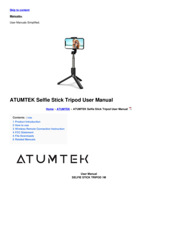
I-1. Package Contents123456781. APC5005. CD2. Ethernet Cable6. Quick Installation Guide3. Console Cable7. Rack-Mount Kit4. Power Adapter8. Wall-Mount Kit2
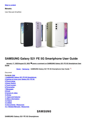
I-2. System Requirements- Existing cable/DSL modem & router- Computer with web browser for access point configurationI-3. Hardware OverviewA. LEDsC. Eject E. WAN/LAN portB. USB 3.0A.B.C.D.E.F.G.D. ConsoleG. ResetF. LAN portsPower, status & storage LEDs.USB 3.0 port for system log and save/restore settings.Eject an attached USB device.Connect a management console.WAN/LAN port 0.LAN ports 1 – 3.Reset the controller to factory default settings.WAN & LAN ports 1 – 3 LEDs:Link/ACTSpeed3
I-4. LED StatusLEDLED ColorLED ashingOffOnFlashingOffOnOffThe controller is on.The controller is starting up.The controller is off.The controller is working properly.Transferring/receiving data.The controller is offline.USB storage attached.USB activity.No USB storage attached.Active link.Network activity.Inactive link.1000 Mbps10/100 MbpsI-5. ResetIf you experience problems with your controller, you can reset the device backto its factory settings. This resets all settings back to default.1.Press and hold the reset button on the front of the controller for at least10 seconds.You may need to use a pin or similar sharp object to push thereset button.2.Wait for the controller to restart. The controller is ready for setup whenthe blue power LED is on.4
I-6. Console/HyperTerminalThe controller can be configured via the “Console” port located on the accesspoint’s side panel using a terminal or a PC-based terminal-emulation program(e.g. HyperTerminal).Use a DB9 straight cable to connect the Console (RS-232 serial port) of theAPC500 and the RS-232 serial port of a terminal or PC.Use the following configuration settings for terminal-emulation programs:Baud RateDataParityStopFlow Control1152008 bitNone1 bitNoneThe console cable pin definition is compatible with Cisco consolecables.5
I-7. Safety InformationIn order to ensure the safe operation of the device and its users, please readand act in accordance with the following safety instructions.1. The controller is designed for indoor use only; do not place the controlleroutdoors.2. Do not place the controller in or near hot/humid places, such as a kitchenor bathroom.3. Do not pull any connected cable with force; carefully disconnect it from thecontroller.4. Handle the controller with care. Accidental damage will void the warrantyof the controller.5. The device contains small parts which are a danger to small children under3 years old. Please keep the controller out of reach of children.6. Do not place the controller on paper, cloth, or other flammable materials.The controller may become hot during use.7. There are no user-serviceable parts inside the controller. If you experienceproblems with the controller, please contact your dealer of purchase andask for help.8. The controller is an electrical device and as such, if it becomes wet for anyreason, do not attempt to touch it without switching the power supply off.Contact an experienced electrical technician for further help.9. If you smell burning or see smoke coming from the controller or poweradapter, then disconnect the controller and power adapter immediately, asfar as it is safely possible to do so. Call your dealer of purchase for help.6
II. Hardware InstallationII-1.Wall MountThe APC500 includes screws to mount your controller to a wall.Remove the rubber feet from the underside of the APC500 bypulling gently before using the wall mount.1.2.Identify and mark correct screw positions on your selected wall.Attach the APC500 to your wall using the included screws, as shown in thediagram.3.Ensure the APC500 is fixed to the wallfirmly and oriented correctly, with thecontroller’s Edimax logo as shown in thediagram.Ensure your controller is securelyattached to the wall.7
II-2.Rack MountThe controller can be mounted in a rack which can be placed in a wiring closetwith other equipment. To install the switch, please follow these steps:1.Attach the mounting brackets on the controller’s side panels (one on eachside) and secure them with the screws provided.2.Use the screws provided with your equipment rack to mount the controlleron the rack and tighten it.8
III. Quick SetupThe APC500 supports central management for up to 32 Edimax Pro accesspoints, reducing costs and facilitating efficient remote AP management.APC500 is simple to setup. An overview of a recommended network is shownbelow:9
The APC500 Controller connects to a network via a switch or directly to arouter, and other connected Edimax Pro access points are automaticallydesignated as Managed APs. Using the APC500 you can configure, monitorand manage all Managed APs (up to 32 connected by switches) from thesingle AP Controller.Ensure you have the latest firmware from the Edimax website foryour Edimax Pro products.1. Connect all APs to a PoE switch which is connected to a gateway/router.You can use your router as a DHCP server or you can laterconfigure your AP Controller as a DHCP server.2. Ensure all APs are powered on and check LEDs.10
3. Connect the APC500 to the PoE switch (LAN port) or gateway/router (WANport) and connect the power supply.4. Connect a computer to the APC500 using an Ethernet cable.11
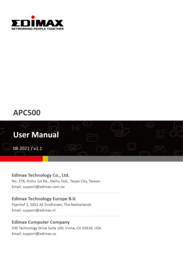
5. Open a web browser and enter the AP Controller’s IP address in theaddress field. The default IP address is 192.168.2.1Your computer’s IP address must be in the same subnet as the APController. Refer to V-1. Configuring your IP Address for help.If you changed the AP Controller’s IP address, or if yourgateway/router uses a DHCP server, ensure you enter the correctIP address. Refer to your gateway/router’s settings.6. Enter the username & password to login. The default username &password are admin & 1234.7. You will arrive at the APC500 Dashboard. APC500 includes a wizard toquickly setup the LAN IP address, admin login & time/date settings for theAPC500, as well as SSID & security for Managed APs. Click “Wizard” in thetop right corner to begin.12
8. Follow the instructions on-screen to complete Steps 1 - 7 and click “Finish”to save the settings. The wizard will help you set up LAN IP address,2.4GHz & 5GHz SSID and security, administrator name & password, time &date settings and Managed APs.13
If any of your Managed APs are not found during Step 5 SelectFree APs, reset the Managed AP to its factory default settings.Refer to the AP’s user manual for help.9. Your APC500 Controller & Managed APs should be fully functional with allof the basic settings configured. Use the top menu to navigate aroundEdimax Pro NMS (Network Management Suite) settings.14
Use Dashboard, Zone Plan, NMS Monitor & NMS Settings to configureManaged APs.Use Local Network & Local Settings to configure your APC500.15
IV. Software LayoutThe top menu features 7 panels: Dashboard, Zone Plan, NMS Monitor, NMSSettings, Local Network, Local Settings & Toolbox.DashboardThe Dashboard panel displays an overview of your network and key systeminformation, with quick links to access configuration options for Managed APsand Managed AP groups. Each panel can be refreshed, collapsed or movedaccording to your preference.16
Zone PlanZone Plan displays a customizable live map of Managed APs for a visualrepresentation of your network coverage. Each AP icon can be moved aroundthe map, and a background image can be uploaded for user-defined locationprofiles using NMS Settings Zone Edit. Options can be configured using themenu on the right side and signal strength is displayed for each AP.17
NMS MonitorThe NMS Monitor panel provides more detailed monitoring informationabout the AP Array than found on the Dashboard, grouped according tocategories in the menu down the left side.18
NMS SettingsNMS Settings provides extensive configuration options for the AP Array. Youcan manage each access point, assign access points into groups, manageWLAN, RADIUS, guest network, guest network, users and scheduling settingsas well as upgrade firmware across multiple access points. The Zone Plan canalso be configured using “Zone Edit”.19
Local NetworkLocal Network settings are for your AP Controller. You can configure the IPaddress and DHCP server of the AP Controller in addition to LAN Port andVLAN settings.20
Local SettingsLocal Settings are for your AP Controller. You can view basic system settingsand logs specifically for the AP Controller, as well as other managementsettings such as date/time, admin accounts, firmware and reset.21
ToolboxThe Toolbox panel provides two network diagnostic tools: ping andtraceroute.22
V. FeaturesDescriptions of the functions of each main panel Dashboard, Zone Plan, NMSMonitor, NMS Settings, Local Network, Local Settings & Toolbox can be foundbelow. When using Edimax NMS, click “Apply” to save changes:Screenshots displayed are examples. The information shown onyour screen will vary depending on your configuration.V-1. LOGIN, LOGOUT & RESTARTIt is recommended that you login to the AP Controller to makeconfigurations to Managed APs.LOGIN1. Connect a computer to the designated AP Controller using an Ethernetcable:2. Open a web browser and enter the AP Controller’s IP address in theaddress field. The default IP address is 192.168.2.123
Your computer’s IP address must be in the same subnet as the APController. Refer to VI-1. Configuring your IP Address for morehelp.If you changed the AP Controller’s IP address, or if yourgateway/router uses a DHCP server, ensure you enter the correctIP address. Refer to your gateway/router’s settings.If using a DHCP server on the network, it is advised to use yourDHCP server’s settings to assign the AP Controller a static IPaddress.3. Enter the username & password to login. The default username &password are admin & 1234.LOGOUTTo logout from Edimax NMS, click “Logout” in the top right corner:RESTARTYou can restart your AP Controller or any Managed AP using Edimax NMS. Torestart your AP Controller go to Local Settings Advanced Reboot andclick “Reboot”.To restart Managed APs click the Restart icon for the specified AP on theDashboard:24
V-2. DASHBOARDThe dashboard displays an overview of your AP array:Use the blue icons above to refresh or collapse each panel in the dashboard.Click and drag to move a panel to suit your preference. You can set thedashboard to auto-refresh every 1 minute, 30 seconds or disable auto-refresh:25
V-2-1. System InformationSystem Information displays information about the AP Controller: ProductName (model), Host Name, MAC Address, IP Address, Firmware Version,System Time and Uptime (time the access point has been on), CPU Usage &Memory Usage.V-2-2. Devices InformationDevices Information is a summary of the number of all devices in the localnetwork: Access Points, Clients Connected, and Rogue (unidentified) Devices.26
V-2-3. Managed APManaged AP displays information about each Managed AP in the localnetwork: Index (reference number), MAC Address, Device Name, Model, IPAddress, 2.4GHz & 5GHz Wireless Channel Number, No. of Clients connectedto each access point, and Status (connected, connecting or disconnected).The search function can be used to locate a specific Managed AP. Type in thesearch box and the list will update:The Status icon displays grey (disconnected), yellow (connecting) or green(connected) for each Managed AP.Each Managed AP has “Action” icons with the following functions:1. DisallowRemove the Managed AP from the AP array and disable connectivity.2. EditEdit various settings for the Managed AP (refer to V-5-1. Access Point).3. Blink LEDThe Managed AP’s LED will flash temporarily to help identify & locateaccess points.27
4. BuzzerThe Managed AP’s buzzer will sound temporarily to help identify & locateaccess points.5. Network ConnectivityGo to the “Network Connectivity” panel to perform a ping or traceroute.6. RestartRestarts the Managed AP.V-2-4. Managed AP GroupManaged APs can be grouped according to your requirements. Managed APGroup displays information about each Managed AP group in the localnetwork: Group Name, MAC Address, Device Name, Model, IP Address, No. ofClients connected to each access point, and Status (connected ordisconnected).To edit Managed AP Groups go to NMS Settings Access Point (refer toV-5-1. Access Point).The search function can be used to locate a specific Managed AP Group. Typein the search box and the list will update:The Status icon displays grey (disconnected), yellow (connecting) or green(connected) for each individual Managed AP.Each Managed AP has “Action” icons with the following functions:28
1. DisallowRemove the Managed AP from the AP array and disable connectivity.2. EditEdit various settings for the Managed AP (refer to V-5-1. Access Point)3. Blink LEDThe Managed AP’s LED will flash temporarily to help identify & locateaccess points.4. BuzzerThe Managed AP’s buzzer will sound temporarily to help identify & locateaccess points.5. Network ConnectivityGo to the “Network Connectivity” panel to perform a ping or traceroute.6. RestartRestarts the Managed AP.V-2-5. Active ClientsActive Clients displays information about each client in the local network:Index (reference number), Client MAC Address, AP MAC Address, WLAN, UserName, Radio (frequency), Signal Strength, Connected Time, Idle Time, Tx & Rx(data transmitted and received) and Vendor of the client device.The search function can be used to locate a specific client. Type in the searchbox and the list will update:29
V-2-6. Active UsersActive Users displays information about each user in the local network viaguest portals: Index (reference number), User Name, MAC Address, IP Address,SSID, Creator, Create Time, Expire Time, Usage Percentage, Vendor & Platformof the user device.The search function can be used to locate a specific client. Type in the searchbox and the list will update:30
V-3. ZONE PLANThe Zone Plan can be fully customized to match your network environment.You can move the AP icons and select different location images (uploadlocation images in NMS Settings Zone Edit) to create a visual map of yourAP array.Use the menu on the right side to make adjustments and mouse-over an APicon in the zone map to see more information. Click an AP icon in the zonemap to select it and display action icons:31
Click and drag an AP icon to move the icon around the zone map. The signalstrength for each AP is displayed according to the “Signal” key in the menu onthe right side:LocationAP NumberSelect a pre-defined location from the dropdown menu. When you upload a locationimage in NMS Settings Zone Edit, it will beavailable for selection here.You can select an AP Group to display in thezone map. Edit AP Groups in NMS Settings Access Point.Use the search box to quickly locate an AP.Use the checkboxes to display APs accordingto 2.4GHz or 5GHz wireless radio frequency.Signal strength key for the signal strengthdisplay around e
3 years old. Please keep the controller out of reach of children. 6. Do not place the controller on paper, cloth, or other flammable materials. The controller may become hot during use. 7. There are no user-serviceable parts inside the controller. If you experience problems with the controller, please contact your dealer of purchase and ask for .