Transcription
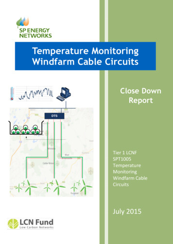
Temperature MonitoringWindfarm Cable CircuitsClose DownReportDTSTier 1 LCNFSPT1005TemperatureMonitoringWindfarm CableCircuitsJuly 2015
For enquiries please contact:Geoff Murphy, Technology Development ManagerSP Energy Networks, Prenton Way, Prenton, Wirral, CH43 3ETEmail: Geoff.Murphy@spenergynetworks.co.uk
Temperature monitoring windfarm cable circuits Tier 1 LCNF Project SPT1005ContentsExecutive Summary . 6Project Background . 6Scope and Objectives . 6Success Criteria. 6Details of the Work Carried Out . 6The Outcomes of the Project . 8Project Performance against Aims, Objectives and Success Criteria . 9Required Modifications to the Planned Approach . 10Significant Variance in Costs and Benefits . 10Lessons Learnt for Future Projects . 10Planned Implementation. 11Facilitate Replication . 121Project Background . 131.1Summary . 131.2Problem . 131.3Solution . 142Scope and Objectives . 153Success Criteria. 164Details of Work Carried Out . 174.1Justification of the Planned Approach . 174.2Project Location. 194.3Trialling Methodology . 224.4Methodology for Selecting the Technology for Monitoring the Cable Temperature . 224.5Methodology for Identifying Trial Sites and Equipment Specification. 254.6Methodology for the Procurement and the Tender Evaluation . 264.7Methodology for the Cable and the Optical Fibre Installation . 274.8Dynamic Cable Rating System Architecture . 334.9Methodology for the Factory Acceptance Test and the Site Acceptance Test . 394.10Methodology for Assigning Zones of Interest . 424.11 Methodology for Validation of the Monitored Optical Fibre Temperature by UsingIndependent Temperature Sensors . 435The Outcomes of the Project . 455.1Overview of the Outcomes of the Project. 463
Temperature monitoring windfarm cable circuits Tier 1 LCNF Project SPT10055.2Outcomes of the DCR Calculation Engine . 465.3Continuous Cable Rating vs. Cyclic Cable Rating . 495.4Loadings of the WindFarm Cable Circuits . 505.5Cable Temperature Profiles. 545.6Causes of variations in temperature profile. 595.7DTS Validation . 626Performance Compared to Original Project Aims, Objectives and Success Criteria . 646.1Project Performance Relative to its Aims and Objectives . 646.2Project Performance Relative to its Success Criteria . 657Required Modifications to the Planned Approach During the Course of the Project . 677.1Installation of the DTS Equipment at East Kilbride South Substation . 677.2Monitoring the Temperature of Additional Cable Circuits . 677.3Modification of the System Architecture Due to IT Security . 687.4Deploying Independent Temperature Sensors for DTS Validation . 688Significant Variance in Expected Costs and Benefits . 698.1Variance in Costs . 698.2IT . 708.3Labour. 708.4Optical Fibre Installation . 708.5DTS and DCR Equipment . 718.6Variance in Benefits. 719Lessons Learnt for Future Projects . 729.1Summary of Learning . 739.2Recommendations on How the Outcome of the Project can be Exploited Further . 759.3Discovery of Significant Problems . 759.4Future Deployment of DCR on a Large Scale. 769.5Effectiveness of Contractual Methods . 7610Planned Implementation . 7711Facilitate Replication . 7911.1Knowledge Required to Replicate the Dynamic Cable Rating System . 7911.2Summary of Intellectual Property Rights (IPR) . 8011.3Data Required to Replicate the Cable Temperature Monitoring System . 8011.4Products Required to Replicate the Cable Temperature Monitoring System. 8111.5Services Required to Replicate the Cable Temperature Monitoring System . 814
Temperature monitoring windfarm cable circuits Tier 1 LCNF Project SPT100511.6Summary of Points of Contact. 83Appendices . 84Appendix A: LCNF First Tier Registration Pro-forma . 84Appendix B: Equipment Specification . 84Appendix C: Method Statements – Cable Ducts & Micro-Ducts . 84Appendix D: Datasets . 845
Temperature monitoring windfarm cable circuits Tier 1 LCNF Project SPT1005Executive SummaryScottish Power Energy Networks (SPEN) has trialled a Distributed Temperature Sensing (DTS)technology to monitor the real-time temperatures and calculate the dynamic thermal ratings ofthree 33kV cable windfarm circuits in Lanarkshire, Scotland. This project, which was funded throughTier 1 Low Carbon Networks (LCN) funding mechanism, has largely delivered its aims and objectiveswithin the time and budget set in the project registration. A summary of the project is given in thefollowing sections.Project BackgroundThree windfarms are scheduled to connect at 33kV to East Kilbride South 275/33kV substation in anarea where there is significant windfarm activity. In order to minimise costs the three cableconnections will share a common trench for the initial 10.7km length from the substation. Given theclose proximity of the three 33kV windfarm cable circuits each has been de-rated to 32.2MW, basedon standard design principles.Two of the three windfarm developers have subsequently asked about the prospect of increasingtheir generation capacity in the future and if any spare headroom capacity might be available.The project funding will include for the installation of micro ducting with optical fibre for all powercircuits, associated Distributed Temperature Sensing (DTS) schemes, determination of real timethermal ratings for the conductor cores, monitoring and analysis to assess spare capacity.Scope and ObjectivesThe scope of the project is to determine dynamic cable ratings for three cable circuits (3 - 33kV) andassess the impact the renewable generation from the three windfarms will have on these circuits.From this analysis the prospect of further network capacity being available will be determined.This project will help inform future cable rating calculations for other projects which could negate orpostpone the requirement for upgrading/reinforcing the Distribution system.Success CriteriaThe project would be deemed successful if:1. The temperature can be monitored across all three cables along the full cable route beingmonitored2. Dynamic cable ratings are determined with associated wind generation output3. Available headroom capacity can be determined for the three windfarm cable circuitsDetails of the Work Carried OutThe project involved the installation of a DTS fibre optic system concurrently with the installation ofthe underground power cables of four windfarms connected at 33kV from East Kilbride Southsubstation, namely Dungavel, Calder Water, West Brown Castle and Ardoch & Over Enochwindfarms. Three out of the four share a trench for the first 10.7km of their routes and they are alsoin close proximity to two existing Whitelee windfarm 275kV cables.6
Temperature monitoring windfarm cable circuits Tier 1 LCNF Project SPT1005The following steps were considered for implementing the real-time cable monitoring system: Selection of the most appropriate technology for monitoring cable temperatures Identification of trial sites for the DTS technology and equipment specification Carrying out of procurement and tender evaluation Design of the system architecture, the communication system and the thermal models Installation of the DTS equipment and optical fibres Factory acceptance tests, commissioning and site acceptance tests Data gathering and system performance analysis Validation of the monitored optical fibre temperatures using independent sensorsThe monitoring system of the new windfarms required optical fibres to be laid along the full length ofthe 33kV circuits, encased in micro-ducts. The gap in the trefoil formation of the 33kV cables waschosen as the optimum position for the micro-ducts and thus the optical fibres.Since the proposed DTS system monitors the temperature of the optical fibre and not that of the33kV cables themselves, appropriate algorithms and thermal modelling were deployed in order tocalculate the DCRs of each of the cables. The DTS system monitors the optical fibre temperatures at30-minute intervals for every 1m of the optical fibre. The DCR algorithms are also run every 30minutes upon receiving the updated fibre temperature data.The DCR methodology is based on an electrical-thermal analogy model, where the thermalcharacteristic of each layer between the optical fibre and the power cable core is modelled. The DCRalgorithms were designed according to IEC 60853 and IEC 60287 and can take into account specificenvironments and different cable constructions and sizes.In order to boost the confidence in the DTS system, the optical fibre temperature measurementswere validated by using independent temperature sensors, Tinytags, at different locations.7
Temperature monitoring windfarm cable circuits Tier 1 LCNF Project SPT1005The Outcomes of the ProjectThe outcomes of the project are outlined as follows:1. Implementation of the DTS system for the Calder Water, West Browncastle, Dungaveland Ardoch & Over Enoch 33kV circuits.2. Monitoring of half-hourly temperature variations of every metre of the optical fibrecables installed along the cable circuits through a user-friendly interface, DC-View,customised specifically for this project.3. Development of transient thermal models for each of the cable circuits, which are usedfor estimating the core temperature of each circuit based on the corresponding opticalfibre temperature.4. Calculations of maximum core temperatures and thermal pinch point locations alongthe cable circuits.5. Validation of temperatures measured by the DTS system by deploying the independenttemperature sensors (Tinytags).6. Gathering and analysis of the DTS data in conjunction with cable circuit loading data toprovide learning on cable temperature profiles and causes of the thermal pinch points.The results of initial analysis on monitored temperature data and cable circuit loadings are as follows: The output power of the windfarms follows a stochastic variation that may allow cablecircuits to dissipate heat during high wind periods. The daily Loss Load Factors (LLF) of theCalder Water and Whitelee cable circuits from 01/01/2014 to 12/03/2015 were calculatedand the results showed that for 80% of the time the LLF of the cable circuits can be below0.5. This suggests a dynamic rating, rather than a continuous rating, could be more suitablefor windfarm cable circuits. However, a DTS system should be in place to monitor theconditions and trigger the require actions to limit the cable loading when cable temperaturesgo beyond the permissible limits.The analysis of the Dungavel fibre temperature data demonstrates the mutual heat impactfrom adjacent cables. The surrounding temperature of the Dungavel circuit increased byaround 8 C during the period when other circuits were carrying the rated output power ofthe associated windfarms. It should be noted that the Dungavel windfarm circuit is notenergised yet and temperature variations seen along this circuit are largely due to thermalimpacts of adjacent circuits.The maximum recorded fibre temperature is for a day with a high LLF and reaches around40.0 C. Although we expect that the core temperature should be higher than the fibretemperature, it seems there could be headroom before reaching the maximum permissibletemperature (78 C). SPEN is planning to investigate this further by carrying out data analysison a 12-month period of data when all the 33kV circuits have been energised undersustained maximum generation conditionsThe location of thermal bottlenecks along the cable circuits seem to remain almostunchanged. That suggests using higher rated cables or back-fills for better heat dissipationsat some locations may help to increase the overall thermal rating of the cable circuits.The causes of thermal bottlenecks identified along the cable circuits are due to:o Crossing point with the Whitelee 275kV cable circuit8
Temperature monitoring windfarm cable circuits Tier 1 LCNF Project SPT1005ooChange in depth of burial, for example before and after crossing a riverThermal effects from adjacent cables and low heat dissipation conditions, e.g. atthe locations where the cable circuits are placed in a pyramid formationThe comparison between an independent temperature sensor and the fibre temperature for a10-day period validated the accuracy of the DTS system at two different locations.Project Performance against Aims, Objectives and Success CriteriaThe project largely delivered its intended aims and objectives. The following key outcomes of theproject are in line with the aims and objectives initially described in the project registration proforma: The DCR of all the 33kV cables, except the Dungavel windfarm circuit, are determined andthe DCR values of cable circuits are available through the DCR and DC-View dashboards,which have been specifically designed and customised for this project. The real-time outputsof the windfarms are also transmitted from SPEN’s PowerNet network to the DCRworkstation. The Dungavel circuit is scheduled to be energised in the third quarter of 2015;once this circuit has been energised, the DCR values will be also available for it.The comparison between the maximum recorded optical fibre temperatures, representingthe temperature around the cable, and the maximum permissible operating limit for cablecore temperatures (78 C for 33kV XLPE) suggests that there may be additional networkcapacity available, which could be utilised if the windfarm developers decided to increasetheir outputs. This is subject to further assessment for at least a 12-month period after theDungavel windfarm is energised in the third quarter of 2015.The following key points demonstrate that the project has met its success criteria: The real-time full length (with 1 metre granularity) temperature profiles of the 33kV CalderWater, West Browncastle circuits and 10.7km (out of 21.4km) of the 33kV Dungavelwindfarm circuit are now available through a user-friendly dashboard. The temperatureprofile of the remaining 10.7km Dungavel circuit will be available after this windfarm circuitis energised in the third quarter of 2015. The delay in energisation of this circuit was due tothe change in the ownership of the windfarm after starting this project.The measured temperature values are then used by DCR algorithms to determine themaximum core temperature and the location it occurs. DCR algorithms use an equivalentthermal circuit simulating the thermal conditions of the cable along with the real-time opticalfibre temperatures.The results of the DCR calculations of the Calder Water and West Browncastle cable circuitsare recorded in the SPEN’s data historian for every 30 minutes. The DCR calculations will bealso available for the Dungavel circuit when this circuit is commissioned in the third quarterof 2015. This data may be used to estimate the available headroom for any period required.9
Temperature monitoring windfarm cable circuits Tier 1 LCNF Project SPT1005Required Modifications to the Planned ApproachThe following modifications were made to the original planned approach: Installation of DTS equipment at East Kilbride South substation rather than the windfarms’substationsMonitoring the temperature of an additional cable circuit, Ardoch & Over EnochModification of the system architecture to meet SPEN’s IT security requirements andincorporation to the corporate systemDeploying independent temperature sensors for DTS validation Significant Variance in Costs and BenefitsThe total actual expenditure was 15,304 below the initial estimated total expenditure of 710,504.There have been some variations in different expenditure elements: IT: 11,623 overspend due to modifications required to the workstations to meet SPENsecurity standardsLabour: 40,071 overspend due to additional resources worked on modifying systemarchitectureOptical fibre installation: 21,627 overspend due to including Ardoch & Over Enoch in theDTS systemDTA and DCR Equipment: 88,624 underspend due to selecting supplier through acompetitive tenderThe variance in benefits of this project is due to the delay in the commissioning of the Dungavelwindfarm circuit, which is scheduled to be energised after the Low Carbon Networks Funding (LCNF)period for this project. The delay in energisation of this circuit was only due to the change in theownership of the windfarm. This project did not fully quantify the additional headroom in the 33kVcable circuit as the actual thermal impact will appear when all 33kV circuits operate under sustainedmaximum generation conditions. Under a newly registered Network Innovation Allowance (NIA)project, SPEN is consequently planning to carry out further data analyses on the cable temperatureprofiles for a 12-month period after all the 33kV circuits have been energised.Lessons Learnt for Future ProjectsThis project provided valuable lessons learnt from the implementation of the DTS and DCR systems.The key learning points are as follows: The installation of the optical fibre cable and micro-ducts in the centre of the trefoil cablearrangement is an effective approach for measuring the surrounding temperature of thecable, as this location can provide the closest temperature to the cable core, whilst the riskof damage to the micro-duct and optical fibre cable is relatively low. The quality control is an important consideration during installation in order to avoid theneed for access to the ducts and optical fibres after its completion. The length of the installed optical fibre cable is longer than the associated power cable asadditional fibre may be coiled up for calibration purposes or as spare. This additional fibrelength should be deducted from DCR calculation.10
Temperature monitoring windfarm cable circuits Tier 1 LCNF Project SPT1005 The initial data analysis of the cable temperature profiles showed that the fibre temperature,representing the cable’s surrounding temperature, reaches 40 C during highest loadingconditions. Although the cable core temperature is higher than the fibre temperature, initialindications suggest that there could be still headroom to reach the 78 C maximumpermissible temperature. This is subject to further assessment for at least a 12-month periodafter the Dungavel windfarm is commissioned in the third quarter of 2015. The temperature profile of a power cable is not flat and varies at different locations alongthe cable route, depending on the proximity to other circuits, surface type and depth ofburial. In order to ensure that third party devices comply with IT security requirements and that thevendors understand them, early IT engagement is required. It is important to have a real-time, end-to-end diagnostics system in place to identify anysource of error in the monitoring or communication equipment and remedial actions.The following significant issues were encountered in the course of project: The delay in commissioning of the Dungavel windfarm circuit did not allow assessing the fullimpact of the DTS system within the lifetime of this project. Integration of third party equipment, which can be considered as “untrusted” to the SPENmain IT network. The DTS equipment uses a different communication protocol from the protocol used inSPEN’s network. The loading of the West Browncastle windfarm circuit was not available for DCR calculationdue to communication issues between the transducer and the RTU.Under a newly registered NIA project, SPEN is planning to investigate the requirement for applicationof a cable temperature monitoring system in an Active Network Management system (ANM) tocontrol the output of the generators based on real-time cable ratings.Planned ImplementationThe results and learning from this project demonstrated that both SPEN and windfarm connectioncustomers could benefit from deploying a real-time cable temperature monitoring system. ScottishPower Energy Networks plan to conduct a new project under the NIA funding mechanism to prepareDTS and DCR systems for full business adoption. The new NIA project has been registered as“Enhanced real-time cable temperature monitoring” (NIA SPEN0003). The following developmentshave been considered in this new NIA project: Data analysis of a 12-month period Requirements for integration of DTS and DCR systems into an Active Network Management(ANM) system architecture Policy documents and technical specifications for future DTS and DCR systems for Business asUsual (BaU) applicationIn addition, the implemented cable temperature monitoring system can be further enhanced by: Deploying for fault location application11
Temperature monitoring windfarm cable circuits Tier 1 LCNF Project SPT1005 Defining ownership of the system and the required maintenance Installation of micro-duct during power cable installation Deployment of independent temperature sensors at possible cable hot spotsFacilitate ReplicationThe cable temperature monitoring system trialled in this project is completely replicable. Theknowledge required to replicate the real-time cable temperature monitoring system includes: DTS system design methodologyDTS system equipment specificationsOptical fibre cable and micro-ducting installation methodologyIT and telecommunications expertiseCable thermal modelling expertiseCable rating standards, technical papers and presentationsThe products required to replicate the real-time cable temperature monitoring system can becategorised as follows: Monitoring equipment Communications and IT equipmentThe services required to replicate the DTS system may be delivered by different organisations listedbelow: the DNO (or consultancy acting on the DNO’s behalf)the monitoring equipment supplierthe DCR thermal modelling providermicro-ducting and optical fibre installation providerThe following points of contacts are also available for any query with regard to replication of the DTSand DCR systems: Geoff Murphy, SP Energy Networks (Geoff.Murphy@sppowersystems.com) David Ruthven, SP Energy Networks (DRuthven@scottishpower.com)12
Temperature monitoring windfarm cable circuits Tier 1 LCNF Project SPT10051 Project BackgroundThree windfarms are scheduled to connect at 33kV to East Kilbride South 275/33kV substation inan area where there is significant windfarm activity. In order to minimise costs the three cableconnections will share a common trench for the initial 10.7km length from the substation. Giventhe close proximity of the three 33kV windfarm cable circuits each has been de-rated to32.2MW, based on standard design principles.Two of the three windfarm developers have subsequently asked about the prospect of increasingtheir generation capacity in the future and if any spare headroom capacity might be available.The project funding will include for the installation of micro ducting with optical fibre for allpower circuits, associated Distributed Temperature Sensing (DTS) schemes, determination of realtime thermal ratings for the conductor cores, monitoring and analysis to assess spare capacity.The full Project Registration Pro-forma is given in Appendix A.1.1 SummaryThree windfarms are to be connected at 33kV to East Kilbride South 275/33kV substation in an areawhere there is significant windfarm activity. In order to minimise costs the three cable connectionswill share a common trench for the initial 10.7km length from the substation. This shared cable routehas been influenced by the need to ensure thermal independence from an existing adjacent 275kVcable that supplies Whitelee Windfarm. Each windfarm cable connection is made up of three singlecore cables laid up in trefoil. Given the close proximity of the three 33kV windfarm cable circuits eachhas been de-rated to 32.2MW.Two of the three windfarm developers have subsequently asked about the prospect of increasingtheir generation capacity in the future and if any spare head room capacity might be available. Theinstallation offers a rare opportunity to consider the dynamic ratings for three parallel adjacent cablecircuits and the prospect for a future trial of active network m
Temperature monitoring windfarm cable circuits Tier 1 LCNF Project SPT1005 7 The following steps were considered for implementing the real-time cable monitoring system: Selection of the most appropriate technology for monitoring cable temperatures Identification of trial sites for the DTS technology and equipment specification