Transcription
3 109 53Maintenance Bypass SwitchInstallation ManualPart. LE09522AA-08/16-01 GF
3 109 53Maintenance Bypass SwitchENFR2ENGLISH3
Index1Introduction41.1 Overview41.2 Guarantee terms52Safety regulations53Installation73.1Introduction73.2Front panel83.3Package content93.4Rack Mount Configuration103.5Tower Configuration113.6Preliminary operations123.6.1 Procedure for Daker DK 1000-2000 VA133.6.2 Procedure for Daker DK 3000 VA154Operations175Troubleshooting186Technical specifications193Installation Manual3 109 53 Maintenance Bypass Switch
1 Introduction1.1 OverviewCongratulations on your purchase of the LEGRAND maintenance bypass switch 3 109 53.This switch (MTBS) has been specifically designed to ensure seamless operation of your criticalload during maintenance and testing or during the unlikely event of a UPS failure.ATTENTIONIt is necessary to read the whole manual carefully before doing any operation.ATTENTIONThe maintenance bypass switch 3 109 53 can only be used with the UPS Daker DK 1000 VA 2000 VA - 3000 VA and Daker DK 1000 VA - 2000 VA - 3000 VA manufactured by LEGRAND.The purpose of this manual is to provide necessary indications to install and use safely the maintenance bypass switch.The reading of these instructions is essential but it cannot substitute the expertise of the technicalpersonnel who must have had adequate preliminary training.The MTBS has been built for the applications specified in this manual. For no reason whatsoeverit is allowed to use it for purposes other than those for which it has been designed.This manual must be kept in a safe, dry place and always be available for consultation. It is suggested to make a copy and to save it.The manual is to be considered an integral part of the maintenance bypass switch and therefore must be kept for the equipment’s useful life cycle.The information included in this manual must not be disclosed to third parties. Any duplication,total or partial, not authorized in writing by the Manufacturer obtained by photostatting or anyother method, even electronically, violates the copyright conditions and can be prosecuted by law.LEGRAND reserves the property rights of this publication and forbids the total or partialreproduction of it without prior written consent.4
1 Introduction1.2 Guarantee termsThe guarantee conditions may vary depending on the country where the maintenance bypass switch 3 109 53 is sold. Check with your local LEGRAND sale representative for validityand duration.The Manufacturer declines all direct and indirect liabilities resulting from:- failure to observe instructions included in this manual;- use by personnel who have not read and thoroughly understood the content of this manual;- use that does not comply with the specific standards used in the country where the equipmentis installed;- modifications made to the equipment, software, functioning logic unless they have been authorized by the Manufacturer in writing;- repairs that have not been authorized by the LEGRAND Technical Assistance Centre;- damage caused intentionally, through negligence, by acts of God, natural phenomena, fire orliquid infiltration.2 Safety regulationsATTENTIONIt is necessary to read carefully these safety provisions and the entire manual before carrying out any operation.DANGERThis product should be installed in compliance with installation rules, preferably by a qualifiedelectrician. Incorrect installation and use can lead to risk of electric shock or fire.Before carrying out the installation, read the instructions and take account of the product’s specificmounting location.Do not open up, dismantle, alter or modify the device except where specifically required to do soby the instructions. All Legrand products must be opened and repaired exclusively by personneltrained and approved by Legrand. Any unauthorized opening or repair completely cancels allliabilities and the rights to replacement and guarantees.Use only Legrand brand accessories.DANGERThe maintenance bypass switch 3 109 53 can only be installed with the UPS Daker DK 1000 VA- 2000 VA - 3000 VA and Daker DK 1000 VA - 2000 VA - 3000 VA completely SWITCHED OFF andUNPLUGGED FROM THE MAINS.5Installation Manual3 109 53 Maintenance Bypass Switch
2 Safety regulationsATTENTIONInspect the maintenance bypass switch immediately after opening the packaging. If it appearsdamaged, do not install it but contact immediately the LEGRAND Technical Service Assistance.ATTENTIONThe UPS, the maintenance bypass switch or the load equipment may be damaged if the installation and operating procedures are not followed.ATTENTION Do not connect the maintenance bypass switch to an ungrounded outlet or extension cords oradapters that eliminate the connection to ground. Do not use this equipment in dusty or corrosive environments or near any flammable objects. The power requirement for each load connected to the maintenance bypass switch must notexceed the individual outlet’s load rating. The equipment is not designed for outdoor use. It can operated under a maximum ambienttemperature of 40 C ( 104 F). The equipment must be installed near a mains socket and it must be easily accessible.ATTENTIONIn case of problems with the maintenance bypass switch, the manual must always be consulted tofind out how to solve them.If the problem persists, contact the LEGRAND Technical Service Assistance which will provide allthe instructions on what to do.6
3 Installation3.1 IntroductionThere are two operation modes offered by the Maintenance Bypass Switch (MTBS).1 - UPS MODE (UPS available): when the MTBS works on UPS mode, the UPS supply directly theloads.2 - UTILITY MODE (maintenance bypass): when the MTBS works on the UTILITY mode, the loads aresupplied by the MTBS. The UPS can be turned off for maintenance or service operation withoutaffecting the loads.7Installation Manual3 109 53 Maintenance Bypass Switch
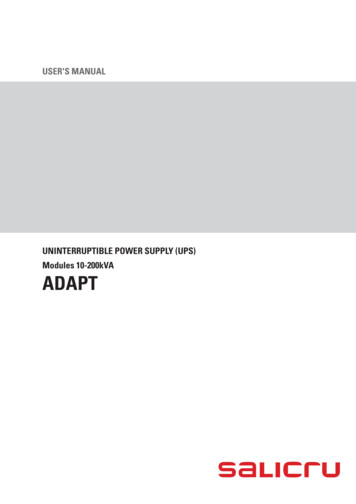
3 Installation3.2 Front panel1.2.3.4.5- 6.7.8UPS output power cord: connect to the UPS output socketsInput Socket: connect to the mains socketCAM SWITCH: Maintenance Bypass SwitchLamps: they indicate the presence of the UPS and of the mainsLoad Sockets: connect to the loadsUPS Input Socket: connect to the UPS Input
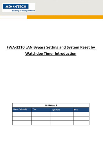
3 Installation3.3 Package content9Installation Manual3 109 53 Maintenance Bypass Switch
3 Installation3.4 Rack Mount ConfigurationStep 1Step 2Step 310
3 Installation3.5 Tower ConfigurationStep 1Step 211Installation Manual3 109 53 Maintenance Bypass Switch
3 Installation3.6 Preliminary operations1. Shut down the loads connected to the UPS and remove the output cable of the UPS.2. Turn off the UPS and remove the input power cord of the UPS from the wall socket.3. Install a utility circuit breaker of max 20 A – curve C for input wiring.4. Make sure the CAM Switch (Maintenance Bypass Switch) is on “UTILITY” position.After these steps, follow one of the next paragraphs according to the model of the UPS installed.12
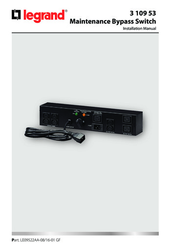
3 Installation3.6.1 Procedure for Daker DK 1000-2000 VAC1 cable IEC320 C19-20C2 cable IEC320 C15-C16C3 cable IEC320 C19-C16C4 cable IEC320 C20-C15C5 power cord Schuko - IEC320 C1913Installation Manual3 109 53 Maintenance Bypass Switch
3 InstallationC1 cable IEC320 C19-20C2 cable IEC320 C15-C16C3 cable IEC320 C19-C16C4 cable IEC320 C20-C15C5 power cord Schuko - IEC320 C191. Plug the input power cord C5 to the input socket of the MTBS [2] and then to the mains socket.The orange lamp of the MTBS [4] will light up.DANGERHazardous voltages are now present in the MTBS.2. Connect the cable C4 to the input socket of the UPS and to the UPS Input Socket of the MTBS [7].DANGERHazardous voltages are now present in the UPS.14
3 Installation3. Connect the cable C3 to the UPS output power cord of the MTBS [1] and to the output socketof the UPS.4. Make sure the loads comply with the voltage and current of the UPS and the mains. If so, connect the loads to the load sockets of the MTBS [5-6] using the cables C2 and C1 or those provided with the UPS. The loads are now supplied directly from the mains through the MTBS.5. Turn on the UPS following the instructions of its user manual. When the UPS is on, the greenlamp of the MTBS [4] will light up.6. Rotate the CAM Switch (Maintenance Bypass Switch) to “UPS” position.3.6.2 Procedure for Daker DK 3000 VAC1 cable IEC320 C19-20C2 cable IEC320 C15-C16C5 power cord Schuko - IEC320 C1915Installation Manual3 109 53 Maintenance Bypass Switch
3 Installation1. Plug the input power cord C5 to the input socket of the MTBS [2] and then to the mains socket.The orange lamp of the MTBS [4] will light up.DANGERHazardous voltages are now present in the MTBS.2. Connect the cable C1 to the input socket of the UPS and to the UPS Input Socket of the MTBS [7].DANGERHazardous voltages are now present in the UPS.3. Connect the cable C1 to the UPS output power cord of the MTBS [1] and to the output socketof the UPS.4. Make sure the loads comply with the voltage and current of the UPS and the mains. If so, connect the loads to the load sockets of the MTBS [5-6] using the cables C2 or those provided withthe UPS. The loads are now supplied directly from the mains through the MTBS.5. Turn on the UPS following the instructions of its user manual. When the UPS is on, the greenlamp of the MTBS [4] will light up.6. Rotate the CAM Switch (Maintenance Bypass Switch) to “UPS” position.16
4 OperationsMake sure to switch the operating modes according to the following procedures:1. UPS MODE UTILITY MODE (Maintenance bypass)Step 1: Make sure the orange lamp of the MTBS is lit. If not, refer to the troubleshooting section.Step 2: Rotate the CAM Switch (Maintenance Bypass Switch) from “UPS” position to “UTILITY”position. At this stage the loads connected are supplied directly by the mains.Step 3: Turn off the UPS.Step 4: Remove the connection between the UPS and the MTBS.Step 5: The maintenance or replacement of the UPS may now proceed.2. UTILITY MODE (Maintenance bypass) UPS MODEStep 1: Connect the input and output of the UPS to the MTBS, then turn on the UPS followingthe instructions of its user manual.Step 2: Make sure that the green lamp of the MTBS is lit. If not, refer to the troubleshooting section.Step 3: Rotate the CAM Switch (Maintenance Bypass Switch) from “UTILITY” position to “UPS”position. At this stage the loads connected are supplied by the UPS.17Installation Manual3 109 53 Maintenance Bypass Switch
5 TroubleshootingIf the MTBS does not operate normally, consult the following table.If the problem cannot be solved, contact the LEGRAND Technical Service Assistance.PROBLEMOrange lampis not litGreen lampof the UPS is not litThe external circuitbreaker has tripped18SOURCE OF THE PROBLEMSOLUTIONNo mainsVerify if the external circuit breakerhas tripped. In this case, reset it.Otherwise contacta qualified electrician.The input power cordconnected to the inputsocket of the MTBS [2] is notconnected properly to themains socketConnect it to the mains socketUPS has no outputRefer to the user manual of the UPSThe input and output of theUPS are not connected to theMTBS properlyConnect them to the MTBS properlyOvercurrent in the MTBS loadsockets [5-6]Reduce the number of loadsconnected
6 Technical specifications3 109 53General characteristicsNet Weight (kg)2.7Dimensions: W D H (mm)87 77 440Ambient specificationsOperating temperature range 32 F to 104 F (0 C to 40 C)Operating relative humidity range20%-80%non-condensingStorage temperature range-4 F to 104 F (-20 C to 40 C)Operating altitude:up to 6560 ft (2000m)Electrical specificationsRating230Vac - 3 kVAFrequency50 Hz - 60 HzRated current16 A maxTransfer Time 6 msDirectives and StandardsSafetyLVD 2014/35/EUEN 60950-119Installation Manual3 109 53 Maintenance Bypass Switch
LEGRANDPro and Consumer ServiceBP 30076 - 87002LIMOGES CEDEX FRANCEwww.legrand.comLegrand se réserve le droit de modifier à tout moment le contenu de cet imprimé et de communiquer,sous n’importe quelle forme et modalité, les changements apportés.
Install a utility circuit breaker of max 20 A - curve C for input wiring. 4. Make sure the CAM Switch (Maintenance Bypass Switch) is on "UTILITY" position. . Rotate the CAM Switch (Maintenance Bypass Switch) to "UPS" position. 3.6.2 Procedure for Daker DK 3000 VA C1 cable IEC320 C19-20 C2 cable IEC320 C15-C16