Transcription
Powerware Series Eaton 9155 UPS8–15 kVAUser's Guide
Class A EMC StatementsFCC Part 15NOTE This equipment has been tested and found to comply with the limits for a Class A digital device, pursuant to part 15 of the FCC Rules.These limits are designed to provide reasonable protection against harmful interference when the equipment is operated in a commercialenvironment. This equipment generates, uses, and can radiate radio frequency energy and, if not installed and used in accordance with theinstruction manual, may cause harmful interference to radio communications. Operation of this equipment in a residential area is likely to causeharmful interference in which case the user will be required to correct the interference at his own expense.ICES-003This Class A Interference Causing Equipment meets all requirements of the Canadian Interference Causing Equipment Regulations ICES‐003.Cet appareil numérique de la classe A respecte toutes les exigences du Reglement sur le matériel brouilleur du Canada.IEC 62040-2Some configurations are classified under IEC 62040-2 as “C2 UPS for Unrestricted Sales Distribution.”VCCI NoticeEaton, Powerware, ABM, Powerware Hot Sync, X-Slot, and FERRUPS are registered trademarks and ConnectUPS is a trademark of Eaton or itssubsidiaries and affiliates. Greenlee is a registered trademark of Greenlee Textron. Modbus is a registered trademark of Schneider Automation.National Electrical Code and NEC are registered trademarks of National Fire Protection Association, Inc. All other trademarks are property of theirrespective companies.ECopyright 2004–2015 Eaton, Raleigh, NC, USA. All rights reserved. No part of this document may be reproduced in any way without the expresswritten approval of Eaton.
Special SymbolsThe following are examples of symbols used on the UPS or accessories to alert you to important information:RISK OF ELECTRIC SHOCK - Observe the warning associated with the risk of electric shock symbol.CAUTION: REFER TO OPERATOR'S MANUAL - Refer to your operator's manual for additional information, suchas important operating and maintenance instructions.This symbol indicates that you should not discard the UPS or the UPS batteries in the trash. This productcontains sealed, lead‐acid batteries and must be disposed of properly. For more information, contact yourlocal recycling/reuse or hazardous waste center.This symbol indicates that you should not discard waste electrical or electronic equipment (WEEE) in thetrash. For proper disposal, contact your local recycling/reuse or hazardous waste center.
Table of Contents1Introduction . . . . . . . . . . . . . . . . . . . . . . . . . . . . . . . . . . . . . . . . . . . . . . . . . . . . . . . .12Safety Warnings . . . . . . . . . . . . . . . . . . . . . . . . . . . . . . . . . . . . . . . . . . . . . . . . . . . .33UPS Setup . . . . . . . . . . . . . . . . . . . . . . . . . . . . . . . . . . . . . . . . . . . . . . . . . . . . . . . . .7Inspecting the Equipment . . . . . . . . . . . . . . . . . . . . . . . . . . . . . . . . . . . . . . . . . . . . . . . . . . . . . . . . . . . . . .Floor Loading . . . . . . . . . . . . . . . . . . . . . . . . . . . . . . . . . . . . . . . . . . . . . . . . . . . . . . . . . . . . . . . . . . . . . . .Clearances . . . . . . . . . . . . . . . . . . . . . . . . . . . . . . . . . . . . . . . . . . . . . . . . . . . . . . . . . . . . . . . . . . . . . . . .Unloading the Cabinet(s) . . . . . . . . . . . . . . . . . . . . . . . . . . . . . . . . . . . . . . . . . . . . . . . . . . . . . . . . . . . . . . .Selecting an Installation Option . . . . . . . . . . . . . . . . . . . . . . . . . . . . . . . . . . . . . . . . . . . . . . . . . . . . . . . . . .7788114UPS Only Installation . . . . . . . . . . . . . . . . . . . . . . . . . . . . . . . . . . . . . . . . . . . . . . . . .135Input Isolation Transformer Installation . . . . . . . . . . . . . . . . . . . . . . . . . . . . . . . . . .176UPS-Mounted Bypass Switch Installation . . . . . . . . . . . . . . . . . . . . . . . . . . . . . . . .25MBM/PDM Setup . . . . . . . . . . . . . . . . . . . . . . . . . . . . . . . . . . . . . . . . . . . . . . . . . . . . . . . . . . . . . . . . . . .Wiring the MBM/PDM . . . . . . . . . . . . . . . . . . . . . . . . . . . . . . . . . . . . . . . . . . . . . . . . . . . . . . . . . . . . . . . .2528Wall-Mounted Bypass Switch Installation . . . . . . . . . . . . . . . . . . . . . . . . . . . . . . . .35Wall-Mounted Bypass Switch Setup . . . . . . . . . . . . . . . . . . . . . . . . . . . . . . . . . . . . . . . . . . . . . . . . . . . . . .Wiring the Wall-Mounted Bypass Switch . . . . . . . . . . . . . . . . . . . . . . . . . . . . . . . . . . . . . . . . . . . . . . . . . . .36378Stabilizing the Cabinet . . . . . . . . . . . . . . . . . . . . . . . . . . . . . . . . . . . . . . . . . . . . . . .439Extended Battery Module Installation . . . . . . . . . . . . . . . . . . . . . . . . . . . . . . . . . . .4710 Communication . . . . . . . . . . . . . . . . . . . . . . . . . . . . . . . . . . . . . . . . . . . . . . . . . . . . .49Installing Communication Options and Control Terminals . . . . . . . . . . . . . . . . . . . . . . . . . . . . . . . . . . . . . . . .Communication Options . . . . . . . . . . . . . . . . . . . . . . . . . . . . . . . . . . . . . . . . . . . . . . . . . . . . . . . . . . . . . . .DB-9 Communication Port . . . . . . . . . . . . . . . . . . . . . . . . . . . . . . . . . . . . . . . . . . . . . . . . . . . . . . . . . . .X-Slot Cards . . . . . . . . . . . . . . . . . . . . . . . . . . . . . . . . . . . . . . . . . . . . . . . . . . . . . . . . . . . . . . . . . . . . .Power Management Software . . . . . . . . . . . . . . . . . . . . . . . . . . . . . . . . . . . . . . . . . . . . . . . . . . . . . . . .Control Terminals . . . . . . . . . . . . . . . . . . . . . . . . . . . . . . . . . . . . . . . . . . . . . . . . . . . . . . . . . . . . . . . . . . .Remote Emergency Power-off . . . . . . . . . . . . . . . . . . . . . . . . . . . . . . . . . . . . . . . . . . . . . . . . . . . . . . . .Relay Output Contacts . . . . . . . . . . . . . . . . . . . . . . . . . . . . . . . . . . . . . . . . . . . . . . . . . . . . . . . . . . . . . .Programmable Signal Inputs . . . . . . . . . . . . . . . . . . . . . . . . . . . . . . . . . . . . . . . . . . . . . . . . . . . . . . . . .50525253545455555611 Operation . . . . . . . . . . . . . . . . . . . . . . . . . . . . . . . . . . . . . . . . . . . . . . . . . . . . . . . . . .57Control Panel Functions . . . . . . . . . . . . . . . . . . . . . . . . . . . . . . . . . . . . . . . . . . . . . . . . . . . . . . . . . . . . . . .Changing the Language . . . . . . . . . . . . . . . . . . . . . . . . . . . . . . . . . . . . . . . . . . . . . . . . . . . . . . . . . . . . .Display Functions . . . . . . . . . . . . . . . . . . . . . . . . . . . . . . . . . . . . . . . . . . . . . . . . . . . . . . . . . . . . . . . . .User Settings . . . . . . . . . . . . . . . . . . . . . . . . . . . . . . . . . . . . . . . . . . . . . . . . . . . . . . . . . . . . . . . . . . . .Initial Startup . . . . . . . . . . . . . . . . . . . . . . . . . . . . . . . . . . . . . . . . . . . . . . . . . . . . . . . . . . . . . . . . . . . . . .UPS Startup . . . . . . . . . . . . . . . . . . . . . . . . . . . . . . . . . . . . . . . . . . . . . . . . . . . . . . . . . . . . . . . . . . . . . . .Normal Mode Startup . . . . . . . . . . . . . . . . . . . . . . . . . . . . . . . . . . . . . . . . . . . . . . . . . . . . . . . . . . . . . .Starting the UPS on Battery . . . . . . . . . . . . . . . . . . . . . . . . . . . . . . . . . . . . . . . . . . . . . . . . . . . . . . . . . .Internal Bypass Startup . . . . . . . . . . . . . . . . . . . . . . . . . . . . . . . . . . . . . . . . . . . . . . . . . . . . . . . . . . . . .Maintenance Bypass Startup . . . . . . . . . . . . . . . . . . . . . . . . . . . . . . . . . . . . . . . . . . . . . . . . . . . . . . . . .Wall-Mounted Maintenance Bypass Startup . . . . . . . . . . . . . . . . . . . . . . . . . . . . . . . . . . . . . . . . . . . . . .Configuring the UPS for EBMs . . . . . . . . . . . . . . . . . . . . . . . . . . . . . . . . . . . . . . . . . . . . . . . . . . . . . . . . . . .UPS Shutdown . . . . . . . . . . . . . . . . . . . . . . . . . . . . . . . . . . . . . . . . . . . . . . . . . . . . . . . . . . . . . . . . . . . . .575858596161616263636464657Eaton 9155 UPS (8–15 kVA) User's Guide S 164201553 Rev G www.eaton.com/powerqualityi
TABLE OF CONTENTS12 UPS Maintenance . . . . . . . . . . . . . . . . . . . . . . . . . . . . . . . . . . . . . . . . . . . . . . . . . . .67UPS and Battery Care . . . . . . . . . . . . . . . . . . . . . . . . . . . . . . . . . . . . . . . . . . . . . . . . . . . . . . . . . . . . . . . . .Storing the UPS and Batteries . . . . . . . . . . . . . . . . . . . . . . . . . . . . . . . . . . . . . . . . . . . . . . . . . . . . . . . . . . .When to Replace Batteries . . . . . . . . . . . . . . . . . . . . . . . . . . . . . . . . . . . . . . . . . . . . . . . . . . . . . . . . . . . . .Recycling the Used Battery or UPS . . . . . . . . . . . . . . . . . . . . . . . . . . . . . . . . . . . . . . . . . . . . . . . . . . . . . . . .Using the UPS-Mounted Maintenance Bypass Switch . . . . . . . . . . . . . . . . . . . . . . . . . . . . . . . . . . . . . . . . . .Using the Wall-Mounted Bypass Switch . . . . . . . . . . . . . . . . . . . . . . . . . . . . . . . . . . . . . . . . . . . . . . . . . . . .67676868687013 Specifications . . . . . . . . . . . . . . . . . . . . . . . . . . . . . . . . . . . . . . . . . . . . . . . . . . . . . .7314 Troubleshooting . . . . . . . . . . . . . . . . . . . . . . . . . . . . . . . . . . . . . . . . . . . . . . . . . . . . .79Typical Alarms and Conditions . . . . . . . . . . . . . . . . . . . . . . . . . . . . . . . . . . . . . . . . . . . . . . . . . . . . . . . . . . .Silencing the Alarm . . . . . . . . . . . . . . . . . . . . . . . . . . . . . . . . . . . . . . . . . . . . . . . . . . . . . . . . . . . . . . . . . .Service and Support . . . . . . . . . . . . . . . . . . . . . . . . . . . . . . . . . . . . . . . . . . . . . . . . . . . . . . . . . . . . . . . . . .79808015 Warranty . . . . . . . . . . . . . . . . . . . . . . . . . . . . . . . . . . . . . . . . . . . . . . . . . . . . . . . . . .81Two-Year Limited Warranty (USA and Canada) . . . . . . . . . . . . . . . . . . . . . . . . . . . . . . . . . . . . . . . . . . . . . . .Load Protection Guarantee (USA and Canada) . . . . . . . . . . . . . . . . . . . . . . . . . . . . . . . . . . . . . . . . . . . . . . . .8182iiEaton 9155 UPS (8–15 kVA) User's Guide S 164201553 Rev G www.eaton.com/powerquality
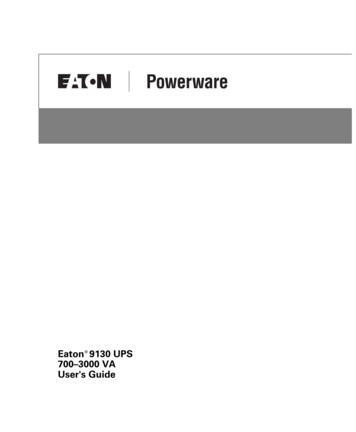
Chapter 1IntroductionThe Eaton 9155 is a double‐conversion, split-phase, online uninterruptible powersystem (UPS) for protecting computer systems and other intelligent devices. It is idealfor protecting essential information technology and electrical engineeringinfrastructure in corporate, telecom, health care, banking, and industrial applications.The UPS provides a steady, well‐regulated power supply for your computing andcommunications equipment, while protecting it from the frequent irregularities thatare inherent in commercially available power. Voltage spikes, power surges,brownouts, and power failures have the potential to corrupt critical data, destroyunsaved work sessions, and in some instances, damage expensive hardware.With the Eaton 9155, you can safely eliminate the effects of electrical linedisturbances and guard the integrity of your systems and equipment. Figure 1 showsthe Eaton 9155 UPS and an optional Extended Battery Module (EBM).Figure 1. The Eaton 9155 UPS and EBM (2-High Cabinets Shown)Providing outstanding performance and reliability, the Eaton 9155's unique benefitsincluding the following:S Online UPS design with pure sine wave output. The UPS filters and regulatesincoming AC power and provides consistent power to your equipment withoutdraining the battery.S More wattage in less space with a 0.9 power factor—protecting more equipmentand leaving more room for expansion.S Support for Powerware Hot Sync paralleling of multiple modules for redundancy orextra capacity.S Input current total harmonic distortion (THD) of less than five percent, using activeinput power factor correction.S ABM technology that uses advanced battery management to increase batteryservice life, optimize recharge time, and provide a warning before the end of usefulbattery life.Eaton 9155 UPS (8–15 kVA) User's Guide S 164201553 Rev G www.eaton.com/powerquality1
INTRODUCTIONS Start-on-battery capability for powering up the UPS even if utility power is notavailable.S Up to four hours of extended runtime with added EBMs.S Emergency shutdown control through the remote emergency power-off (REPO)port.S Standard communication options with a DB-9 serial port, relay output contacts, andprogrammable signal inputs.S Optional X-Slot cards with enhanced communication capabilities for increasedpower protection and control.S Advanced power management with the Software Suite CD for graceful shutdownsand power monitoring.S Backed by worldwide agency approvals.The following options for the Eaton 9155 are available:S Maintenance Bypass Module (MBM)The optional MBM is installed on the UPS rear panel and is used to bypass theUPS during maintenance or servicing. The maintenance bypass switch on theMBM provides a Make-Before-Break (MBB) wrap-around bypass for UPS servicewithout shutting down the load.S Power Distribution Module (PDM)The optional PDM provides the same functionality as the MBM and also comesequipped with several different types of output receptacles.S Wall-Mounted Bypass SwitchThe optional wall-mounted bypass switch is used to bypass the UPS duringmaintenance or servicing, providing wrap-around bypass for UPS service withoutshutting down the load.S Parallel Tie CabinetAn optional parallel system with up to three UPSs can be installed to provide aparallel capacity and/or redundant system. This load sharing system provides morecapacity than a single UPS and can provide backup, depending on the load andconfiguration. In addition, when one UPS is taken out of service for maintenance oris not operating properly, a redundant UPS continues to supply uninterruptedpower to the critical load. A parallel Powerware Hot Sync Controller Area Network(CAN) Bridge Card provides connectivity for system metering and operational modecontrol. The parallel system consists of two to three UPSs, each with a parallelCAN Bridge Card, and a parallel tie cabinet. Refer to the Eaton 9155 Parallel UPS(8–15 kVA) User's Guide for more information.S Input Isolation TransformerThe optional input isolation transformer is located at the bottom of a 3-high UPSmodel. The input isolation transformer provides a neutral from a 208V or 240Vinput source with 240V output and can be wired to the UPS or to an MBM/PDM.S Seismic KitThe optional seismic kit secures the UPS and optional EBMs for Zone 4 seismicinstallations.2Eaton 9155 UPS (8–15 kVA) User's Guide S 164201553 Rev G www.eaton.com/powerquality
Chapter 2Safety WarningsIMPORTANT SAFETY INSTRUCTIONSSAVE THESE INSTRUCTIONSThis manual contains important instructions that you should follow during installation and maintenance ofthe UPS and batteries. Please read all instructions before operating the equipment and save this manual forfuture reference.DANGERThis UPS contains LETHAL VOLTAGES. All repairs and service should be performed by AUTHORIZEDSERVICE PERSONNEL ONLY. There are NO USER SERVICEABLE PARTS inside the UPS.WARNINGS This UPS contains its own energy source (batteries). The UPS output may carry live voltage even whenthe UPS is not connected to an AC supply.S To reduce the risk of fire or electric shock, install this UPS in a temperature and humidity controlled,indoor environment, free of conductive contaminants. Ambient temperature must not exceed 40 C(104 F). Do not operate near water or excessive humidity (95% maximum).S To reduce the risk of fire, connect only to a circuit provided with 100 amperes maximum branch circuitovercurrent protection in accordance with the National Electrical Code, ANSI/NFPA 70.S Output overcurrent protection and disconnect switch must be provided by others.CAUTIONS Batteries can present a risk of electrical shock or burn from high short circuit current. Observe properprecautions. Servicing should be performed by qualified service personnel knowledgeable of batteriesand required precautions. Keep unauthorized personnel away from batteries.S Proper disposal of batteries is required. Refer to your local codes for disposal requirements.S Never dispose of batteries in a fire. Batteries may explode when exposed to flame.Eaton 9155 UPS (8–15 kVA) User's Guide S 164201553 Rev G www.eaton.com/powerquality3
SAFETY WARNINGSConsignes de SécuritéCONSIGNES DE SÉCURITÉ IMPORTANTESCONSERVER CES INSTRUCTIONSCe manuel comporte des instructions importantes que vous êtes invité à suivre lors de toute procédured'installation et de maintenance des batteries et de l'onduleur. Veuillez consulter entièrement cesinstructions avant de faire fonctionner l'équipement et conserver ce manuel afin de pouvoir vous y reporterultérieurement.DANGER!Cet onduleur contient des TENSIONS MORTELLES. Toute opération d'entretien et de réparation doit êtreEXCLUSIVEMENT CONFIÉE A UN PERSONNEL QUALIFIÉ AGRÉÉ. AUCUNE PIÈCE RÉPARABLE PARL'UTILISATEUR ne se trouve dans l'onduleur.AVERTISSEMENT!S Cette onduleur possède sa propre source d'alimentation (batteries). Il est possible que la sortie del'onduleur soit sous tension même lorsque l'onduleur n'est pas connectée à une alimentation CA.S Pour réduire les risques d'incendie et de décharge électrique, installer l'onduleur uniquement à l'intérieur,dans un lieu dépourvu de matériaux conducteurs, où la température et l'humidité ambiantes sontcontrôlées. La température ambiante ne doit pas dépasser 40 C. Ne pas utiliser à proximité d'eau oudans une atmosphère excessivement humide (95 % maximum).S Afin de réduire les risques d'incendie, n'effectuez le raccordement qu'avec un circuit muni d'uneprotection de surintensité du circuit de dérivation maximum de 100 ampères conformément au CodeÉlectrique National (National Electrical Code) des États-Unis ANSI/NFPA 70.S La protection de surintensité de sortie ainsi que le sectionneur doivent être fournis par des tiers.ATTENTION!S Les batteries peuvent présenter un risque de choc électrique ou de brûlure provenant d'un courant decourt-circuit haute intensité. Observez les précautions appropriées. L'entretien doit être réalisé par dupersonnel qualifié connaissant bien les batteries et les précautions nécessaires. N'autorisez aucunpersonnel non qualifié à manipuler les batteries.S Une mise au rebut réglementaire des batteries est obligatoire. Consulter les règlements en vigueur dansvotre localité.S Ne jamais jeter les batteries au feu. L'exposition aux flammes risque de les faire exploser.4Eaton 9155 UPS (8–15 kVA) User's Guide S 164201553 Rev G www.eaton.com/powerquality
SAFETY WARNINGSAdvertencias de SeguridadINSTRUCCIONES DE SEGURIDAD IMPORTANTESGUARDE ESTAS INSTRUCCIONESEste manual contiene instrucciones importantes que debe seguir durante la instalación y el mantenimientodel SIE y de las baterías. Por favor, lea todas las instrucciones antes de poner en funcionamiento el equipo yguarde este manual para referencia en el futuro.PELIGROEste SIE contiene VOLTAJES MORTALES. Todas las reparaciones y el servicio técnico deben ser efectuadosSOLAMENTE POR PERSONAL DE SERVICIO TÉCNICO AUTORIZADO. No hay NINGUNA PARTE QUE ELUSUARIO PUEDA REPARAR dentro del SIE.ADVERTENCIAS Este SIE contiene su propia fuente de energía (baterías). La salida del SIE puede transportar voltaje activoaun cuando el SIE no esté conectado con una fuente de CA.S Para reducir el riesgo de incendio o de choque eléctrico, instale este SIE en un lugar cubierto, contemperatura y humedad controladas, libre de contaminantes conductores. La temperatura ambiente nodebe exceder los 40 C. No trabaje cerca del agua o con humedad excesiva (95% máximo).S Para reducir el riesgo de incendio, realice la conexión únicamente hacia un circuito que cuente con unmáximo de 100 amperios de protección contra sobrecorriente de circuito derivado, de acuerdo con elCódigo Eléctrico Nacional, ANSI/NFPA 70.S La protección contra sobrecorriente de salida y el conmutador de desconexión debe suministrarse porparte de terceros.PRECAUCIÓNS Las baterías pueden constituir un riesgo de descarga eléctrica o quemaduras por corriente alta de cortocircuito. Adopte las precauciones debidas. Personal calificado de servicio que conozca de baterías y estéal tanto de las precauciones requeridas debe darle servicio al equipo. Mantenga al personal no autorizadoalejado de las baterías.S Es necesario desechar las baterías de un modo adecuado. Consulte las normas locales para conocer losrequisitos pertinentes.S Nunca deseche las baterías en el fuego. Las baterías pueden explotar si se las expone a la llama.Eaton 9155 UPS (8–15 kVA) User's Guide S 164201553 Rev G www.eaton.com/powerquality5
SAFETY WARNINGS6Eaton 9155 UPS (8–15 kVA) User's Guide S 164201553 Rev G www.eaton.com/powerquality
Chapter 3UPS SetupThis chapter describes:S Equipment inspectionS Floor loading and clearancesS Unloading the cabinet(s)S Selecting an installation optionThe instructions are intended for the chief operator/system supervisor, electricalconsultants, and installation electricians. Local regulations and electrical code must befollowed during the UPS installation.Inspecting the EquipmentIf any equipment has been damaged during shipment, keep the shipping and packingmaterials for the carrier or place of purchase and file a claim for shipping damage. Ifyou discover damage after acceptance, file a claim for concealed damage.To file a claim for shipping damage or concealed damage: 1) File with the carrierwithin 15 days of receipt of the equipment; 2) Send a copy of the damage claimwithin 15 days to your service representative.NOTE Check the battery recharge date on the packaging label. If the date has expired and the batterieswere never recharged, do not use the UPS. Contact your service representative.Floor LoadingWhen planning the installation, consider the UPS weight for floor loading. Thestrength of the installation surface must be adequate for point and distributedloadings. The approximate weights are shown in the following table.Standard Model Floor Loadings (2-High/3-High Cabinets)Eaton 9155Maximum Weight (lb)Point Loading (lb/in2)Distributed Loading (lb/ft2)2-High UPS352881663-High UPS5901482783-High UPS with Isolation Transformer5581402632-High EBM4801202263-High EBM7101783352-High UPS with Maintenance Bypass Module(MBM) or Power Distribution Module (PDM)3-High UPS with MBM/PDMEaton 9155 UPS (8–15 kVA) User's Guide S 164201553 Rev G www.eaton.com/powerquality7
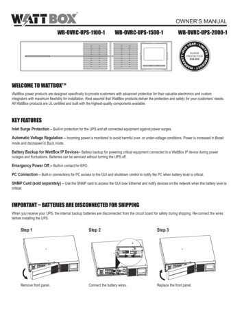
UPS SETUPClearancesThe following clearances are recommended for the Eaton 9155 UPS:From Front of Cabinet36” (91.4 cm) working spaceFrom Back of Cabinet6” (15.2 cm) without an MBM/PDM installed; with an MBM/PDMinstalled, clearance is determined by the customer-supplied matingplugUnloading the Cabinet(s)The following tools are required for unloading the cabinet(s):S 15 mm wrench or socketS 7 mm nutdriver or socketCAUTIONThe UPS and Extended Battery Module (EBM) are heavy (see page 7). Unloading the cabinets requires atleast two people to safely remove the cabinets from the pallet.To remove the UPS or EBM from the shipping pallet:1.Remove the two M10 bolts securing the stabilizing bracket to the pallet (seeFigure 2).M10 BoltsFigure 2. Removing the Stabilizing Bracket Bolts8Eaton 9155 UPS (8–15 kVA) User's Guide S 164201553 Rev G www.eaton.com/powerquality
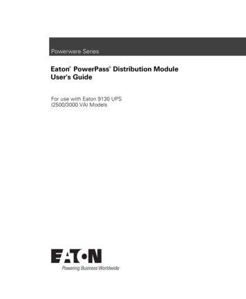
UPS SETUP2.Remove the four M4 screws securing the stabilizing bracket to the cabinet rearpanel and remove the bracket (see Figure 3). Retain the hardware for later use.NOTE Be sure to retain the stabilizing bracket and hardware for later re-assembly onto the cabinet.3.Remove the front cover from the bottom cabinet to access the front shippingbracket.Press and release the handle latch at the bottom of the cover and then lift thecover up and off the cabinet.4.Remove the three M10 bolts securing the rear shipping pad to the pallet andremove the shipping pad (see Figure 3).NOTE Hold the back of the cabinet so that the bolts can be removed easily without the cabinet rollingbackward.5.Remove the two M10 bolts securing the front shipping bracket and remove thebracket (see Figure 3).If needed, adjust the leveling feet to release the bracket.Front ShippingBracketM10 BoltsStabilizing BracketM10 BoltsM4 ScrewsShipping PadFigure 3. Removing the Brackets and Shipping Pad6.Reinstall the front cover removed in Step 3.Hang the top edge of the cover on the cabinet first, then lower the bottom edgeand snap into place.Eaton 9155 UPS (8–15 kVA) User's Guide S 164201553 Rev G www.eaton.com/powerquality9
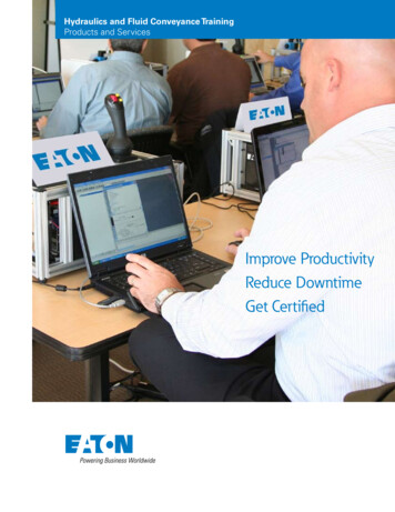
UPS SETUPNOTE Be sure to support the front and back of the cabinet when rolling it off the pallet to prevent tipping.7.Slowly roll the cabinet toward the rear of the pallet. Once the pallet tilts, continuerolling the cabinet down the pallet until the cabinet touches the floor (seeFigure 4).If needed, adjust the leveling feet so that the cabinet will roll.Figure 4. Unloading the Cabinet8.With the cabinet supported, slowly pull the pallet away from the cabinet (seeFigure 5).Figure 5. Removing the Pallet9.10Roll the cabinet to the desired location.Eaton 9155 UPS (8–15 kVA) User's Guide S 164201553 Rev G www.eaton.com/powerquality
UPS SETUPSelecting an Installation OptionYou are now ready to install the Eaton 9155 UPS. Select one of the followinginstallation options according to your UPS configuration:UPS ConfigurationInstallation ChapterUPS onlyChapter 4, “UPS Only Installation” on page 13UPS with an optional input isolationtransformerChapter 5, “Input Isolation Transformer Installation” on page 17UPS with an optional UPS-mountedbypass switchChapter 6, “UPS-Mounted Bypass Switch Installation” onpage 25UPS with an optional wall-mountedbypass switchChapter 7, “Wall-Mounted Bypass Switch Installation” onpage 35Parallel UPS configurationRefer to the Eaton 9155 Parallel UPS (8–15 kVA) User's Guide.Eaton 9155 UPS (8–15 kVA) User's Guide S 164201553 Rev G www.eaton.com/powerquality11
UPS SETUP12Eaton 9155 UPS (8–15 kVA) User's Guide S 164201553 Rev G www.eaton.com/powerquality
Chapter 4UPS Only InstallationThe Eaton 9155 has the following power connections:S 2‐phase (L1 and L2), neutral, and ground connection for rectifier/bypass inputS 2‐phase (L1 and L2), neutral, and ground connection for load outputThe nominal input/output voltages are:S 100/200, 110/220, or 120/240 Vac with 180 phase displacementS 120/208 or 127/220 Vac with 120 phase displacementOutput overcurrent protection and disconnect switch must be provided by others.Figure 8 on page 16 shows a oneline diagram of the UPS.WARNINGOnly qualified service personnel (such as a licensed electrician) should perform the UPS installation andinitial startup. Risk of electrical shock.To hardwire the UPS:1.Verify that the electrical connections to the installation site have been properlyinstalled.2.A wall-mounted, user‐supplied, readily‐accessible disconnection device must beincorporated in the input wiring.Compare the circuit breaker ratings and wire sizes to the specifications in Table 1on page 15.NOTE To accommodate the feature of easy system expandability, it is recommended that initial installationof the Eaton 9155 UPS contain wiring to support the maximum capacity of the UPS cabinet.3.Switch off utility power to the distribution point where the UPS will beconnected. Be absolutely sure there is no power.4.Determine your equipment's grounding requirements according to your localelectrical code.5.Verify that the UPS battery circuit breaker is in the OFF position (see Figure 6).Eaton 9155 UPS (8–15 kVA) User's Guide S 164201553 Rev G www.eaton.com/powerquality13
UPS ONLY INSTALLATIONONOFFBattery Circuit BreakerUPS WiringAccess CoverConduit LandingFigure 6. UPS Rear View6.Remove the UPS wiring access cover and retain (see Figure 6).7.Install conduit and hardwire the input, output, and ground terminations for theUPS.See Table 1 for specifications and Figure 7 for a detailed view of the UPSterminal block.148.Replace the UPS wiring access cover.9.Continue to “Stabilizing the Cabinet” on page 43 to complete the UPSinstallation.Eaton 9155 UPS (8–15 kVA) User's Guide S 164201553 Rev G www.eaton.com/powerquality
UPS ONLY INSTALLATIONNOTE Input neutral must be wired for proper operation. Failure to connect an input neutral will void thewarranty.Table 1. UPS Terminal Block (TB1) WiringWire FunctionInputGroundAUXNot UsedOutputTerminal PositionInput Circuit BreakerRatingMinimum Wire Size*TB1‐18 AWGTB1‐2-1 and 2-2—TB1‐2A-1 and 2A-2—8 kVA10 kVA12 kVA15 kVA4 AWG (21.2 mm2)3 AWG (26.7 mm2)2 AWG (33.6 mm2)2 AWG (33.6 L1TB1‐68 AWGNeutralTB1‐78 AWGL2TB1‐88 AWGTB1‐8A-1 and 8A-2—TB1‐98 AWGNot UsedGroundTighteningTorqueConduit Connection(Entry Size)25 lb in(2.83 Nm)2” access hole for1‐1/2” conduit25 lb in(2.83 Nm)2” access hole for1‐1/2” conduit* Use only 75 C-rated copper wire. Minimum wire size is based on 120/208 full load ratings applied to NEC Code Table 310‐16. Code may require alarger AWG size than shown in this table because of temperature, number of conductors in the conduit, or long service runs. Follow localrequirements.1TB134567898A2 2AInputOutputFigure 7. UPS Terminal BlockEaton 9155 UPS (8–15 kVA) User's Guide S 164201553 Rev G www.eaton.com/powerquality15
UPS ONLY INSTALLATIONFigure 8. UPS Only Wiring Diagram16Eaton 9155 UPS (8–15 kVA) User's Guide S 164201553
Wall-Mounted Bypass Switch The optional wall-mounted bypass switch is used to bypass the UPS during maintenance or servicing, providing wrap-around bypass for UPS service without shutting down the load. Parallel Tie Cabinet An optional parallel system with up to three UPSs can be installed to provide a parallel capacity and/or redundant system.