Transcription
FWA-3210 LAN Bypass Setting and System Reset byWatchdog Timer IntroductionAPPROVALSName (printed)TitleSignatureDate
FWA-3210 Setting introductionVersion: V1.0Page 2 of 39HISTORYRevisionV1.0DatePersonDescription
FWA-3210 Setting introductionVersion: V1.0Page 3 of 39CONTENT1. LAN Bypass Utility introduction . 41.1LAN Bypass Utility Setup . 41.2LAN Bypass Utility Command description . 51.3FWA-3210 Onboard LAN bypass. 71.41.51.3.1Hardware description: . 71.3.2LAN Bypass Example: . 81.3.3BIOS setting and Clear Application/Utility Bypass Setting by BIOS. 10LAN Bypass control for NAEM-0103 LAN module . 121.4.1Hardware description . 121.4.2Example for NMC-0103: . 13LAN Bypass control for NMC-0107/0803 LAN module . 151.5.1Hardware description . 151.5.2Example for NMC-0107/NMC-0803: . 172. IPMI command for LAN Bypass . 192.1IPMI environment Setting . 192.2IPMI Command for LAN Bypass Setting . 202.3FWA-3210 Onboard LAN Bypass description: . 212.42.52.3.1Hardware description . 212.3.2IPMI LAN Bypass setting . 22IPMI LAN Bypass control for NAEM-0103 LAN module . 262.4.1Hardware description . 262.4.2IPMI LAN Bypass setting . 27IPMI LAN Bypass control for NMC-0107/0803 LAN module: . 312.5.1Hardware description . 312.5.2IPMI LAN Bypass setting . 333. FWA-3210 System Reset by watchdog timer . 38
FWA-3210 Setting introductionVersion: V1.0Page 4 of 391. LAN BYPASS UTILITY INTRODUCTION1.1 LAN Bypass Utility SetupFWA-3210 provide 2 SM BUS LAN bypass utilityOne is 3210 ByPass Standard NOCMOS V0.07; it doesn’t record LAN bypass status in CMOS, and followsBIOS setting from “Onboard LAN Bypass Configuration”The other is 3210 ByPass Standard V0.07, it records LAN bypass status in CMOS and it will bypass CMOSsetting from “Onboard LAN Bypass Configuration”Kindly choose suitable SM BUS LAN bypass utility for customer applicationThese utility installation/control methods are identical, below steps are using 3210 ByPass Standard V0.07to introduce utility installation & control setting.Please copy 3210 ByPass Standard V0.07.tar.gz file into Linux system and uncompress this file.Kindly use bpsmak to compile 3210bps programBelow list files are SM bus LAN bypass/WDT LAN bypass utility & source code for FWA-3210.
FWA-3210 Setting introductionVersion: V1.0Page 5 of 391.2 LAN Bypass Utility Command description3210 Onboard LAN Bypass function:3210bps -n0 -s0 -p[y] m[z] [time]-n0 : Onboard Lan control.-s0 : Onboard Lans only populate slot 0, s0.-p[y] : Pair Index, p1 - p3.m[z] : Bypass modes. Onboard lans support m1,m3,m4,m5.m1 : Power on direct-connect/Power off disconnectm3 : Power on direct-connect/Power off Bypassm4 : Power on Bypass/Power off Bypassm5: Timer mode: Power on direct-connect/Timer out Bypass/Power off Bypass[time] : m5 Wachdog Time out base on 1.0 seconds (1 time 255).time will be truncated to integral number.Usage:-- Print Help information:-- Set Pair 1 to m1:-- Set Pair 2 to m3:-- Set Pair 3 to m4:-- Set Pair 1 to m5 (4 seconds) :-- Get Pair 2 Status:3210bps -n0 -h3210bps -n0 -s0 -p1 m13210bps -n0 -s0 -p2 m33210bps -n0 -s0 -p3 m43210bps -n0 -s0 -p1 m5 43210bps -n0 -s0 -p2 stsNMC-0103 for 3210 Bypass functions:3210bps -n1 -s[x] -p[y] m[z] [time]-n1: NMC-0103 control.-s[x] : Slot Index, s1 - s2.-p[y] : Pair Index, p1 - p2.(P1 and P2 are set to the same mode when control P1 or P2)m[z] : Bypass modes.NMC-0103 support m1,m3,m4,m5.m1 : Power on direct-connect/Power off disconnectm3 : Power on direct-connect/Power off Bypassm4 : Power on Bypass/Power off Bypassm5: Timer mode: Power on direct-connect/Timer out Bypass/Power off Bypass[time] : m5 Wachdog Time out base on 1.0 seconds (1 time 255).time will be truncated to integral number.Notes : All NMC-0103 use the same watchdog. This mode will affect other slot card'smode.Usage:-- Print Help information:-- Set Slot 1 Pairs to m1:3210bps -n1 -h3210bps -n1 -s1 -p1 m1
FWA-3210 Setting introductionVersion: V1.0Page 6 of 39-- Set Slot 2 Pairs to m3:3210bps -n1 -s2 -p1 m3-- Set Slot 1 Pairs to m4:3210bps -n1 -s1 -p1 m4-- Set Slot 2 Pairs to m5 (4 seconds) : 3210bps -n1 -s2 -p1 m5 4-- Get Slot 1 Pairs Status:3210bps -n1 -s1 -p1 stsNMC-0107 for 3210 Bypass function:3210bps -n2 -s[x] -p[y] m[z] [time]-n2: NMC-0107 control.-s[x] : Slot Index, s1 - s2.-p[y] : Pair Index, p1 - p4.m[z]: bypass modesm1 : Power on direct-connect/Power off disconnectm2 : Power on disconnect/Power off disconnectm3 : Power on direct-connect/Power off bypassm4 : Power on bypass/Power off bypassm5 : Timer mode: Power on direct-connect/Timer out Bypass/Power off Bypassm6 : Timer mode: Power on Bypass/Timer out direct-connect/Power off Bypassm7 : Timer mode: Power on disconnect/Timer out direct-connect/Power off disconnect[time] : m5 m6 m7 Wachdog Time out base on 1.0 seconds (0.0 time 6553.5).Usage:-- Print Help information:3210bps -n2 -h-- Set Slot 1 Pair 1 to m1:3210bps -n2 -s1 -p1 m1-- Set Slot 1 Pair 2 to m5 (time-out 5.5s): 3210bps -n2 -s1 -p2 m5 5.5-- Set Slot 2 Pair 1 to m3:3210bps -n2 -s2 -p1 m3
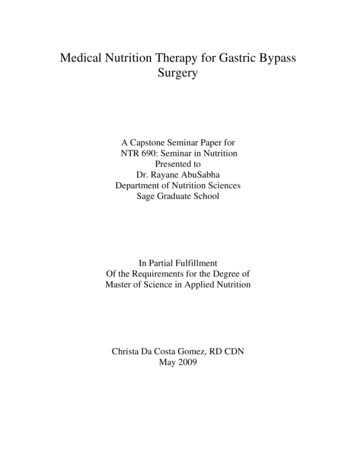
FWA-3210 Setting introductionVersion: V1.0Page 7 of 391.3 FWA-3210 Onboard LAN bypass1.3.1 Hardware description:1. Onboard LAN Bypass descriptionLAN Bypass Pair 1: LAN1 & LAN2LAN Bypass Pair 2: LAN3 & LAN4LAN Bypass Pair 3: LAN5 & LAN62. FWA-3210 Onboard LAN LED status definition:Speed LED:LED indicationDescriptionGreenConnect to 1 Gbps networkAmberConnect to 100 Mbps networkOffConnect to 10 Mbps network or network disconnectedLink/Active LED:LED indicationDescriptionGreenNetwork ConnectedGreen blinkingActive modeAmberLAN Bypass modeAmber blinkingLAN Disconnect mode
FWA-3210 Setting introductionVersion: V1.0Page 8 of 391.3.2 LAN Bypass Example:1. Set FWA-3210 onboard LAN Pair 1(LAN1/LAN2) as Power on direct-connect/Power off disconnect &check LAN bypass status-- 3210bps –n0 –s0 –p1 m1-- 3210bps –n0 –s0 –p1 sts2. Set FWA-3210 onboard LAN Pair 2 (LAN3/LAN4) as Power on direct-connect/Power off Bypass & checkLAN bypass status-- 3210bps –n0 –s0 –p2 m3-- 3210bps –n0 –s0 –p2 sts3. Set FWA-3210 onboard LAN Pair 3(LAN5/LAN6) as Power on Bypass/Power off Bypass.& check LANbypass status-- 3210bps –n0 –s0 –p3 m4-- 3210bps –n0 –s0 –p3 sts4. Set FWA-3210 onboard LAN Pair1 (LAN1/LAN2) as WDT Bypass timeout 10sec & check WDT Bypassstatus-- 3210bps –n0 –s0 –p1 m5 10-- 3210bps –n0 –s0 –p1 sts
FWA-3210 Setting introductionVersion: V1.0Page 9 of 395. Set FWA-3210 onboard LAN Pair 2 (LAN3/LAN4) as WDT Bypass timeout 20sec & check WDT Bypassstatus-- 3210bps –n0 –s0 –p2 m5 20-- 3210bps –s0 –p2 sts6. Set FWA-3210 onboard LAN Pair 3 (LAN5/LAN6) as WDT Bypass timeout 30sec & check WDT Bypassstatus (After timeout)-- 3210bps –n0 –s0 –p3 m5 30-- 3210bps –n0 –s0 –p3 sts
FWA-3210 Setting introductionVersion: V1.0Page 10 of 391.3.3 BIOS setting and Clear Application/Utility Bypass Setting by BIOSFWA-3210 BIOS provide 3 LAN bypass mode setting, the below lists are Bypass status description:Bypass Disabled: Power on direct-connect/Power off disconnect (m1)Bypass On:Power on Bypass/Power off Bypass (m4)Bypass Off:Power on direct-connect / Power off Bypass (m3)SM Bus LAN bypass utility(3210 ByPass Standard V0.07.tar.gz) will record LAN bypass status inCMOS, onboard LAN bypass will keep last status of utility setting when system reboot or power off(unplug power cord)If customer needs to clear onboard LAN bypass last status of utility setting, kindly choose BIOS settingAdvanced - LAN ByPass Configuration - “Clear AP ByPass Setting”,The item will clear the last setting by LAN Bypass utility
FWA-3210 Setting introductionVersion: V1.0Page 11 of 39
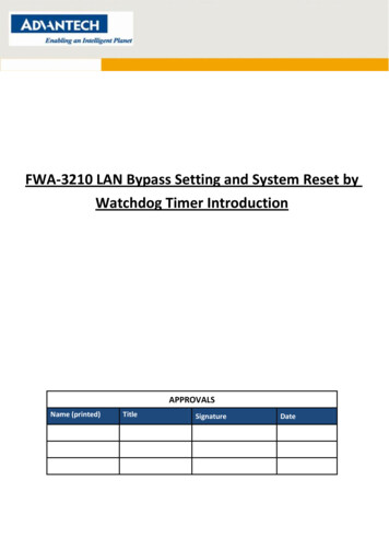
FWA-3210 Setting introductionVersion: V1.0Page 12 of 391.4 LAN Bypass control for NAEM-0103 LAN module1.4.1 Hardware descriptionFWA-3210 is using the “PCA9545 I2C switch” to redirect the SM-Bus from motherboard to NMC by middleboard; the I/O address of “PCA9545 I2C switch” is E0.3. NAEM-0103 LAN Bypass description4. NAEM-0103 LAN LED status definition:Speed LED:LED indicationDescriptionGreenConnect to 1 Gbps networkAmberConnect to 100 Mbps networkOff:Connect to 10 Mbps network or network disconnected
FWA-3210 Setting introductionVersion: V1.0Page 13 of 39Link/Active LED:LED indicationDescriptionGreenNetwork ConnectedGreen blinkingActive modeOffLAN Bypass & Disconnect mode1.4.2 Example for NMC-0103:1. Set NAME-0103 All LAN ports @ NMC Slot#1 as Power on direct-connect/Power off disconnect and checkNAEM-0103 status.-- 3210bps –n1 –s1 –p1 m1-- 3210bps –n1 –s1 –p2 m1-- 3210bps –n1 –s1 –p1 sts-- 3210bps –n1 –s1 –p2 sts2. Set NAME-0103 All LAN ports @ NMC Slot#2 as Power on direct-connect/Power off Bypass. and checkNAEM-0103 status.-- 3210bps –s2 –p1 m3-- 3210bps –s2 –p2 m3-- 3210bps –s2 –p1 sts-- 3210bps –s2 –p2 sts
FWA-3210 Setting introductionVersion: V1.0Page 14 of 393. Set NAME-0103 All LAN ports @ NMC Slot#1 & #2 as WDT LAN WDT Bypass timeout 10sec & checkWDT Bypass status.Notes : All NMC-0103 use the same watchdog. This mode will affect other slot card's mode.-- 3210bps –n1 –s2 –p1 m5 100-- 3210bps –n1 –s2 –p1 sts
FWA-3210 Setting introductionVersion: V1.0Page 15 of 391.5 LAN Bypass control for NMC-0107/0803 LAN module1.5.1 Hardware descriptionFWA-3210 is using the “PCA9545 I2C switch” to redirect the SM-Bus from motherboard to NMC by middleboard; the I/O address of “PCA9545 I2C switch” is E0.1. NMC-0107 LAN Bypass descriptionLAN Bypass Pair 1: LAN1 & LAN2 @ NMC SlotLAN Bypass Pair 2: LAN3 & LAN4 @ NMC Slot
FWA-3210 Setting introductionVersion: V1.0Page 16 of 392. NMC-0803 / LAN Bypass descriptionLAN Bypass Pair 1: LAN1 & LAN2 @ NMC SlotLAN Bypass Pair 2: LAN3 & LAN4 @ NMC SlotLAN Bypass Pair 3: LAN5 & LAN6 @ NMC SlotLAN Bypass Pair 4: LAN7 & LAN8 @ NMC Slot3. NMC-0107/0803 LAN LED status definition:Speed LED:LED indicationDescriptionGreenConnect to 1 Gbps networkAmberConnect to 100 Mbps networkOffConnect to 10 Mbps network or network disconnectedLink/Active LED:LED indicationDescriptionGreenNetwork ConnectedGreen blinkingActive modeAmberLAN Bypass modeAmber blinkingLAN Disconnect mode
FWA-3210 Setting introductionVersion: V1.0Page 17 of 391.5.2 Example for NMC-0107/NMC-0803:1. Set LAN Bypass status of NMC-0803 LAN1/LAN2(P1) @ NMC Slot#1 as Power on direct-Connect /Poweroff Disconnect-- 3210bps –n2 –s1 –p1 m12. Set LAN Bypass status of NMC-0803 LAN3/LAN4(P2) @ NMC Slot#1 as Power on Disconnect /Power offDisconnect-- 3210bps -n2 –s1 –p2 m23. Set LAN Bypass status of NMC-0803 LAN1/LAN2(P1) @ NMC Slot#2 as Power on direct-Connect /Poweroff Bypass-- 3210bps –n2 –s2 –p1 m34. Set LAN Bypass status of NMC-0803 LAN1/LAN2(P2) @ NMC Slot#2 as Power on Bypass /Power offBypass-- 3210bps –n2 –s2 –p2 m45. Set Watchdog LAN Bypass status of NMC-0803 LAN5/LAN6(P3) @ NMC Slot#2 as 10sec Power ondirect-connect/Timer out Bypass/Power off Bypass-- 3210bps –n2 –s2 –p3 m5 106. Set Watchdog LAN Bypass status of NMC-0803 LAN7/LAN8 (P4) @ NMC Slot#2 as 20sec Timer mode:Power on Bypass/Timer out direct-connect/Power off Bypass-- 3210bps –n2 –s2 –p4 m6 20
FWA-3210 Setting introductionVersion: V1.0Page 18 of 397. Set Watchdog LAN bypass status of NMC-0803 LAN5/LAN6(P3) @ NMC Slot#1 as 100sec Timer mode:Power on disconnect/Timer out direct-connect/Power off disconnect-- 3210bps –n2 –s1 –p3 m7 100Notes: When customer needs to use NMC-0107 2 WDT timers or NMC-0803 4 WDT timer, theWDT timer needs to set P1 P2 (NMC-0107), P1 P2 P3 P4 (NMC-0803), otherwise, WDTfunctions is unable to work normally
FWA-3210 Setting introductionVersion: V1.0Page 19 of 392. IPMI COMMAND FOR LAN BYPASS2.1 IPMI environment SettingPlease use the below commands to set the IPMI environment before using the IPMI command.modprobe ipmi devintfmodprobe ipmi msghandlermodprobe ipmi si type kcs ports 0xca8 regspacings 4The below list is the FWA-3210 BMC default information included user name & passwordUser name:adminPassword:adminParameter NameDefault ValueIP Address of LAN interface0.0.0.0Subnet Address of LAN interface255.255.255.0User IDs(User/Password/Privilege/Channels)User ID 1:NULL/NULL/USER/LANUser ID 2:admin/admin/ADMINISTRATOR/LANLAN ChannelPEF AlertingDisabledPer-message AuthenticationDisabledUser Level AuthenticationEnabledAccess ModeAlways AvailablePrivilege Level LimitAdministratorIPMB Slave Address20hKCS Base AddressCA8h (SMS)
FWA-3210 Setting introductionVersion: V1.02.2 IPMI Command for LAN Bypass Setting#ipmitool i2c bus 4 0xAA 0xBB 0xCC 0xDD 0xEE0xAA: SM-BUS I/O Address0x40: FWA-3210 motherboard PCA9554 for Latch Control0x44: FWA-3210 motherboard PCA9554 for LAN Bypass0x9c: FWA-3210 motherboard CPLD for Watchdog Timer0xE0: FWA-3210 middle board PCA9545 I2C Switch0x4c: NMC PCA9554 for Latch Control and LAN BypassPage 20 of 39
FWA-3210 Setting introductionVersion: V1.0Page 21 of 392.3 FWA-3210 Onboard LAN Bypass description:2.3.1 Hardware description1. Onboard LAN Bypass descriptionLAN Bypass Pair 1: LAN1 & LAN2LAN Bypass Pair 2: LAN3 & LAN4LAN Bypass Pair 3: LAN5 & LAN62. FWA-3210 Onboard LAN LED status definition:Speed LED:LED indicationDescriptionGreenConnect to 1 Gbps networkAmberConnect to 100 Mbps networkOffConnect to 10 Mbps network or network disconnectedLink/Active LED:LED indicationDescriptionGreenNetwork ConnectedGreen blinkingActive modeAmberLAN Bypass modeAmber blinkingLAN Disconnect mode
FWA-3210 Setting introductionVersion: V1.0Page 22 of 392.3.2 IPMI LAN Bypass setting1. FWA-3210 onboard LAN Bypass and Direct-connect setting#ipmitool i2c bus 4 0xAA 0xBB 0xCC 0xDD et all Latch function as Enable modeXX is the HEX value in the below“On” is mean LAN bypass enable, network data is through each LAN pair“Off” is mean LAN bypass disable, network data is through LAN chip“Dis” is mean LAN disconnect, network data is not through each LAN pair & LAN chipBCD100000001000000110000010 10000011 10000100 10000101 10000110 ffOff2. FWA-3210 onboard LAN Disconnect and Direct-connect setting#ipmitool i2c bus 4 0xAA 0xBB 0xCC 0xDD et all Latch function as Disable modeXX is the HEX value in the belowBCD100000001000000110000010 10000011 10000100 10000101 10000110 isDisOffOffOffOff
FWA-3210 Setting introductionVersion: V1.0Page 23 of 393. FWA-3210 onboard LAN Disconnect and Direct-connect under power off setting#ipmitool i2c bus 4 0xAA 0xBB 0xCC 0xDD onSet all LAN function as connected modeXX is the HEX value in the below11010101 11010110 11011001 11011010 11100101 11100110 11101001 isDisPower off status(power off & unplug power nDisDisLAN5/6OnOnOnOnDisDisDisDis4. Onboard LAN WDT bypass command#ipmitool i2c bus 4 0xAA 0xBB 0xCC 0xDD N Pair 1 Watchdog Bypass function (XX 0:Disable; 1:Enable)20x9c0x000x020xXXLAN Pair 1 Watchdog timer, XX range is 0 FF(0 255 sec)30x9c0x000x030xXXLAN Pair 2 Watchdog Bypass function (XX 0:Disable; 1:Enable)40x9c0x000x040xXXLAN Pair 2 Watchdog timer, XX range is 0 FF(0 255 sec)50x9c0x000x050xXXLAN Pair 3 Watchdog Bypass function (XX 0:Disable; 1:Enable)60x9c0x000x060xXXLAN Pair 3 Watchdog timer, XX range is 0 FF(0 255 sec)
FWA-3210 Setting introductionVersion: V1.0Example:1. Set onboard LAN Pair 1 (LAN1/LAN2) as WDT bypass enabled & timeout in 5 sec#ipmitool i2c bus 4 0x9c 0x00 0x01 0x01#ipmitool i2c bus 4 0x9c 0x00 0x02 0x052. Set onboard LAN Pair 1 (LAN1/LAN2) as WDT bypass disabled#ipmitool i2c bus 4 0x9c 0x00 0x01 0x003. Set onboard LAN Pair 2(LAN3/LAN4) as WDT bypass enabled & timeout in 10 sec#ipmitool i2c bus 4 0x9c 0x00 0x03 0x01#ipmitool i2c bus 4 0x9c 0x00 0x04 0x0A4. Set onboard LAN Pair 2 (LAN3/LAN4) as WDT bypass disabled#ipmitool i2c bus 4 0x9c 0x00 0x03 0x005. Set onboard LAN Pair 3(LAN5/LAN6) as WDT bypass enabled & timeout in 15 sec#ipmitool i2c bus 4 0x9c 0x00 0x05 0x01#ipmitool i2c bus 4 0x9c 0x00 0x06 0x0APage 24 of 39
FWA-3210 Setting introductionVersion: V1.06. Set onboard LAN Pair 3 (LAN5/LAN6) as WDT bypass disabled#ipmitool i2c bus 4 0x9c 0x00 0x05 0x00Page 25 of 39
FWA-3210 Setting introductionVersion: V1.0Page 26 of 392.4 IPMI LAN Bypass control for NAEM-0103 LAN module2.4.1 Hardware descriptionFWA-3210 is using the “PCA9545 I2C switch” to redirect the SM-Bus from motherboard to NMC by middleboard, the I/O address of “PCA9545 I2C switch” is E0.1. NAEM-0103 LAN Bypass descriptionLAN Bypass Pair 1: LAN1 & LAN2 @ NMC SlotLAN Bypass Pair 2: LAN3 & LAN4 @ NMC Slot2. NAEM-0103 LAN LED status definition:Speed LED:LED indicationDescriptionGreenConnect to 1 Gbps networkAmberConnect to 100 Mbps networkOff:Connect to 10 Mbps network or network disconnected
FWA-3210 Setting introductionVersion: V1.0Page 27 of 39Link/Active LED:LED indicationDescriptionGreenNetwork ConnectedGreen blinkingActive modeOffLAN Bypass & Disconnect mode2.4.2 IPMI LAN Bypass setting1. NMC Slot Switch Command#ipmitool i2c bus 4 0xAA 0xBB 0xCC 0xDD itch to NMC Slot#220xe00x000x000x02Switch to NMC Slot#1Example for NMC Slot Switch Command1. Switch to NMC Slot#2 Command:#ipmitool i2c bus 4 0xe0 0x00 0x00 0x012. Switch to NMC Slot#1 Command:#ipmitool i2c bus 4 0xe0 0x00 0x00 0x02
FWA-3210 Setting introductionVersion: V1.0Page 28 of 392. LAN Bypass on/LAN Direct-connect/LAN Disconnect command#ipmitool i2c bus 4 0xAA 0xBB 0xCC 0xDD N bypass valueValuePower on DescriptionPower off description0X00P1 & P2 LAN bypass OffP1 & P2 disconnect0x55P1 LAN bypass On & P2 LAN bypass OffP1 & P2 LAN bypass0x33P1 LAN bypass Off & P2 LAN bypass OnP1 & P2 LAN bypass0x77P1 & P2 LAN bypass OffP1 & P2 LAN bypass0x11P1 & P2 LAN bypass ONP1 & P2 LAN bypass0x22P1 & P2 LAN bypass OffP1 & P2 disconnect0x44P1 & P2 LAN bypass OffP1 & P2 disconnect0x66P1 & P2 LAN bypass OffP1 & P2 disconnectExample for NMC-0103 LAN bypass:1. Set NMC Slot#1 NAEM-0103 as “P1 & P2 LAN bypass ON ”#ipmitool i2c bus 4 0xe0 0x00 0x00 0x02 – switch to NMC Slot#1#ipmitool i2c bus 4 0x4c 0x00 0x03 0x00 –initial NAEM-0103#ipmitool i2c bus 4 0x4c 0x00 0x01 0x11
FWA-3210 Setting introductionVersion: V1.02. Set NMC Slot#1 NAEM-0103 as “P1 LAN bypass Off & P2 LAN bypass On ”#ipmitool i2c bus 4 0xe0 0x00 0x00 0x02 – switch to NMC Slot#1#ipmitool i2c bus 4 0x4c 0x00 0x03 0x00 –initial NAEM-0103#ipmitool i2c bus 4 0x4c 0x00 0x01 0x333. Set NMC Slot#2 NAEM-0103 as “P1 LAN bypass On & P2 LAN bypass Off ”#ipmitool i2c bus 4 0xe0 0x00 0x00 0x01 – switch to NMC Slot#2#ipmitool i2c bus 4 0x4c 0x00 0x03 0x00 –initial NAEM-0103#ipmitool i2c bus 4 0x4c 0x00 0x01 0x554. Set NMC Slot#2 NAEM-0103 as “P1 & P2 LAN bypass Off ”#ipmitool i2c bus 4 0xe0 0x00 0x00 0x01 – switch to NMC Slot#2#ipmitool i2c bus 4 0x4c 0x00 0x03 0x00 –initial NAEM-0103#ipmitool i2c bus 4 0x4c 0x00 0x01 0x77Page 29 of 39
FWA-3210 Setting introductionVersion: V1.0Page 30 of 393. NAEM-0103 LAN WDT bypass command#ipmitool i2c bus 4 0xAA 0xBB 0xCC 0xDD 0xEE10xAA0xBB0xCC0xDDDescription0x9c0x000x0X0x0XX 0x0X (WDT offset) 0xXX (value)OffsetDescription0X07NMC slot1 & NMC slot2 Watchdog Bypass function. Value 0: Disable; 1: Enable.0X08NMC slot1 & NMC slot2 Watchdog timer, value range is 0 FF(0 255 sec)Example for NAEM-0103 WDT LAN bypass1. Set NAEM-0103 All LAN port of NMC slot1 & NMC slot2 as WDT bypass enabled & timeout in 15 sec#ipmitool i2c bus 4 0x9c 0x00 0x07 0x01#ipmitool i2c bus 4 0x9c 0x00 0x08 0x052. Set NAEM-0103 All LAN port of NMC slot1 & NMC slot2 as WDT bypass disable
FWA-3210 Setting introductionVersion: V1.0Page 31 of 392.5 IPMI LAN Bypass control for NMC-0107/0803 LAN module:2.5.1 Hardware descriptionFWA-3210 is using a “PCA9545 I2C switch” to redirect the SM-Bus from motherboard to NMC card by middleboard, the I/O address of “PCA9545 I2C switch” is E0.1. NMC-0107 LAN Bypass descriptionLAN Bypass Pair 1: LAN1 & LAN2 @ NMC SlotLAN Bypass Pair 2: LAN3 & LAN4 @ NMC Slot2. NMC-0803 LAN Bypass description
FWA-3210 Setting introductionVersion: V1.0Page 32 of 39LAN Bypass Pair 1: LAN1 & LAN2 @ NMC SlotLAN Bypass Pair 2: LAN3 & LAN4 @ NMC SlotLAN Bypass Pair 3: LAN5 & LAN6 @ NMC SlotLAN Bypass Pair 4: LAN7 & LAN8 @ NMC Slot3. NMC-0107/0803 LAN LED status definition:Speed LED:LED indicationDescriptionGreenConnect to 1 Gbps networkAmberConnect to 100 Mbps networkOff:Connect to 10 Mbps network or network disconnectedLink/Active LED:LED indicationDescriptionGreenNetwork ConnectedGreen blinkingActive modeAmberLAN Bypass modeAmber blinkingLAN Disconnect mode
FWA-3210 Setting introductionVersion: V1.0Page 33 of 392.5.2 IPMI LAN Bypass setting1. NMC Slot Switch Command#ipmitool i2c bus 4 0xAA 0xBB 0xCC 0xDD itch to NMC Slot#220xe00x000x000x02Switch to NMC Slot#1Example for NMC Slot Switch Command1. Switch to NMC Slot#2 Command:#ipmitool i2c bus 4 0xe0 0x00 0x00 0x012. Switch to NMC Slot#1 Command:#ipmitool i2c bus 4 0xe0 0x00 0x00 0x022. LAN Bypass on/LAN Direct-connect/LAN Disconnect command#ipmitool i2c bus 4 0xAA 0xBB 0xCC 0xDD ntrol LAN pair 1 (LAN1/LAN2), 0xXX(LAN bypass value)20x4c0x000x200xXXControl LAN pair 2 (LAN3/LAN4), 0xXX(LAN bypass value)30x4c0x000x300xXXControl LAN pair 3 (LAN5/LAN6), 0xXX(LAN bypass value)40x4c0x000x400xXXControl LAN pair 4 (LAN7/LAN8), 0xXX(LAN bypass value)NMC-0107/0803 LAN bypass Value table:ValueDescription0x81power on direct-connect/power off disconnect0x82power on disconnect/power off disconnect0x83power on direct-connect/ power off bypass0x84power on bypass/ power off bypass
FWA-3210 Setting introductionVersion: V1.0Page 34 of 39Example for LAN Bypass on/LAN Direct-connect/LAN Disconnect command1. Set NMC Slot#2 LAN pair 1(LAN1/LAN2) as “power on direct-connect/power off disconnect”#ipmitool i2c bus 4 0xe0 0x00 0x00 0x01 – switch to NMC Slot#2#ipmitool i2c bus 4 0x4c 0x00 0x10 0x81 0x002. Set NMC Slot#2 LAN pair 2(LAN3/LAN4) as “power on disconnect/power off disconnect”#ipmitool i2c bus 4 0xe0 0x00 0x00 0x01 – switch to NMC Slot#2#ipmitool i2c bus 4 0x4c 0x00 0x20 0x82 0x003. Set NMC Slot#1 LAN pair 1(LAN1/LAN2) as “power on direct-connect/ power off bypass”#ipmitool i2c bus 4 0xe0 0x00 0x00 0x02 – switch to NMC Slot#1#ipmitool i2c bus 4 0x4c 0x00 0x10 0x83 0x004. Set NMC Slot#1 LAN pair 2(LAN1/LAN2) as “power on bypass/ power off bypass”#ipmitool i2c bus 4 0xe0 0x00 0x00 0x02 – switch to NMC Slot#1#ipmitool i2c bus 4 0x4c 0x00 0x20 0x84 0x00
FWA-3210 Setting introductionVersion: V1.0Page 35 of 393. IPMI WDT LAN Bypass setting#ipmitool i2c bus 4 0xAA 0xBB 0xCC 0xDD ntrol LAN pair 1 (LAN1/LAN2), 0xXX(LAN bypass value)20x4c0x000x200xXXControl LAN pair 2 (LAN3/LAN4), 0xXX(LAN bypass value)30x4c0x000x300xXXControl LAN pair 3 (LAN5/LAN6), 0xXX(LAN bypass value)40x4c0x000x400xXXControl LAN pair 4 (LAN7/LAN8), 0xXX(LAN bypass value)NMC-0107/0803 LAN Bypass ValueValueDescription0x85Timer mode: power on direct-connect Timeout Bypass / power off Bypass0x86Timer mode: power on Bypass Timeout direct-connect / power off Bypass0x87Timer mode: power on disconnect Timeout direct-connect / power off disconnect#ipmitool i2c bus 4 0xAA 0xBB 0xCC 0xDD XX0xXXWDT Port 1 (LAN1/LAN2), 0xXX(WDT time value)40x4c0x000x220xXX0xXXWDT Port 2 (LAN3/LAN4), 0xXX(WDT time value)60x4c0x000x320xXX0xXXWDT Port 3 (LAN5/LAN6), 0xXX(WDT time value)80x4c0x000x420xXX0xXXWDT Port 4 (LAN7/LAN8), 0xXX(WDT time value)80x4c0x000x500x000x00Reload P1/P2/P3/P4 WDTNMC-0107/0803 WDT Time ValeValueDescription0x00 0x01 0xFF 0XFFTime unit is 0.1sec (0.1 6553.5 sec)Notes: When customer needs to use NMC-0107 2 WDT timers or NMC-0803 4 WDT timer, theWDT timer needs to set P1 P2 (NMC-0107), P1 P2 P3 P4 (NMC-0803), otherwise, WDTfunctions is unable to work normally
FWA-3210 Setting introductionVersion: V1.0Page 36 of 39Example for PMI WDT LAN Bypass setting1. Set NMC Slot#2 LAN pair 1(LAN1/LAN2) as “WDT Timer mode: power on direct-connect TimeoutBypass / power off Bypass”#ipmitool i2c bus 4 0xe0 0x00 0x00 0x01 – switch to NMC Slot#2#ipmitool i2c bus 4 0x4c 0x00 0x12 0x00 0x30 – set WDT timer as 30H (4.8 sec)#ipmitool i2c bus 4 0x4c 0x00 0x10 0x85 0x002. Set NMC Slot#2 LAN pair 2(LAN3/LAN4) as “WDT Timer mode: power on Bypass Timeoutdirect-connect / power off Bypass”#ipmitool i2c bus 4 0xe0 0x00 0x00 0x01 – switch to NMC Slot#2#ipmitool i2c bus 4 0x4c 0x00 0x22 0x00 0x60 – set WDT timer as 60H(9.6 sec)#ipmitool i2c bus 4 0x4c 0x00 0x20 0x86 0x003. Set NMC Slot#2 LAN pair 3(LAN5/LAN6) as “WDT Timer mode: power on disconnect Timeoutdirect-connect / power off disconnect” (PS: LAN pair 3(LAN5/LAN6) is only for NMC-0803)#ipmitool i2c bus 4 0xe0 0x00 0x00 0x01 – switch to NMC Slot#2#ipmitool i2c bus 4 0x4c 0x00 0x32 0x00 0x90 – set WDT timer as 90H(14.4 sec)#ipmitool i2c bus 4 0x4c 0x00 0x30 0x87 0x00
FWA-3210 Setting introductionVersion: V1.0Page 37 of 394. Reload NMC Slot#2 all LAN bypass setting#ipmitool i2c bus 4 0xe0 0x00 0x00 0x01 – switch to NMC Slot#2#ipmitool i2c bus 4 0x4c 0x00 0x50– Reload P1/P2/P3/P4 WDT
FWA-3210 Setting introductionVersion: V1.0Page 38 of 393. FWA-3210 SYSTEM RESET BY WATCHDOG TIMER1. Utility installationPlease copy 3210 wdt V0.02.tar.gz file into Linux system and uncompress this file.Customer may use gcc –o 3210wdt 3210wdt.c to re-complier WDT utility when customer modify samplecode.2. FWA-3210 WDT Reboot command description:3210wdt [time count [time type]][time count]Timeout value: 1 time count 255.[time type]Timeout type: 's' : second; 'm' : minute.Usage:3212wdt -h;Help.3212wdt;DEFAULT Setting : 8 seconds timeout.3210wdt 10 s;Setting : 10 seconds timeout.3210wdt 5 m;Setting : 5 minutes timeout.3. Example for FWA-32101. Set FWA-3210 WDT reboot as 8 seconds timeout (default setting).#./3210wdt
FWA-3210 Setting introductionVersion: V1.02. Set FWA-3210 WDT reboot as 20 seconds timeout#./3210wdt 20 s3. Set FWA-3210 WDT reboot as 2 minutes timeout#./3210wdt 2 mPage 39 of 39
FWA-3210 System Reset by watchdog timer. 38. FWA-3210 Setting introduction Version: V1.0 Page 4 of 39 1. LAN BYPASS UTILITY INTRODUCTION 1.1 LAN Bypass Utility Setup FWA-3210 provide 2 SM_BUS LAN bypass utility One is 3210_ByPass_Standard_NOCMOS_V0.07; it doesn't record LAN bypass status in CMOS, and follows BIOS setting from "Onboard .