Transcription
59TP6APerformance Two---Stage, Variable Speed4---Way MultipoiseCondensing Gas FurnaceSeries 1Product DataA11263The 59TP6A Multipoise Variable--Speed Condensing Gas Furnacefeatures the two--stage Performancet System. The Comfort HeatRtechnology two--stage gas valve is at the heart of the comfortprovided by this furnace, along with the variable--speed ECMblower motor, and two--speed inducer motor. With an Annual FuelUtilization Efficiency (AFUE) up to 96.5%, the PerformancetSeries two--stage gas furnace provides exceptional savings whencompared to standard gas furnaces. This Performance Gas Furnacealso features 4--way multipoise installation flexibility, and isavailable in eight model sizes. The 59TP6A can be vented fordirect vent/two--pipe, ventilated combustion air, or single--pipeapplications. All units meet California Air Quality ManagementDistrict emission requirements. All sizes are design certified inCanada.STANDARD FEATURESS All sizes meet ENERGY STARR Version 4.0 criteria for gasfurnaces: 95 AFUE; AMACF electrical rating; 2% or lesscabinet airflow leakage.S Quiet operation. Compare for yourself at HVACpartners.com.S Ideal height 35” (889 mm) cabinet: short enough for taller coils,but still allows enough room for service.S Silicon Nitride Perfect Light Hot Surface Igniter.S SmartEvap technology helps control humidity levels in thehome when used with a compatible humidity control system.S ComfortFan technology allows control of continuous fanspeed from a compatible thermostat.S 4--way multipoise design for upflow, downflow or horizontalinstallations, with unique vent elbow and optional through-the--cabinet downflow venting capability.S Full--featured variable--speed blower motor, two--speed inducermotor, and two--stage gas valve.S Self--diagnostics.S Adjustable blower speed for cooling, continuous fan, anddehumidification.S Aluminized--steel primary heat exchanger.S Stainless--steel condensing secondary heat exchanger.S Propane convertible (See Accessory list).S Factory--configured ready for upflow applications.S Fully--insulated casing including blower section.S Convenient Air Purifier and Humidifier connections.S Direct--vent/sealed combustion, single--pipe venting orventilated combustion air.S Installation flexibility: sidewall or vertical vent.S Residential installations may be eligible for consumer financingthrough the Retail Credit Program.S Certified to leak 2% or less of nominal air conditioning CFMdelivered when pressurized to 1--in. water column with allpresent air inlets, air outlets, and condensate drain port(s) sealed.TM1
CASINGDIMENSIONS(IN.)SAP E21112059TP6A100E21112059TP6A120E241122RATED HEATING OUTPUT†(BTUH)HEATING AIRFLOWHDWHighLowAFUECFM‡ (HighHeatingCFM (LowHeating)High HeatingESP(in. 0.150.200.20COOLINGCFM @ 0.5ESP(in. W.C.)MOTOR HP 51/21/21/23/43/411159TP6A{Capacity in accordance with DOE test procedures. Ratings are position dependent. See rating plate.‡Minimum heat CFM when low---heat rise adjustment switch (SW 1 ---3) and comfort/efficiency adjustment switch (SW1 ---4) on control center are OFF.ESP --- External Static PressureFEATURES AND BENEFITSComfort Heat TechnologyR — This feature with AdaptiveControl is a proprietary function that promotes homeownercomfort through two stages of heating. This Carrier furnace offers apatented algorithm that continually monitors and adjusts furnaceoperation by looking at both current and past conditions todetermine the most effective stage of heating and the amount oftime to run each stage, every cycle.SmartEvapt Technology — When paired with a compatiblethermostat, this dehumidification feature overrides the coolingblower off-delay when there is a call for dehumidification. Bydeactivating the blower off-delay, SmartEvap technology preventscondensate that remains on the coil after a dehumidification cyclefrom re-humidifying throughout the home. This results in reducedhumidity and a more comfortable indoor environment for thehomeowner.Unlike competitive systems, SmartEvap technology only overridesthe cooling blower off delay when humidity control is needed.Once humidity is back in control, SmartEvap re-enables theenergy-saving cooling blower off-delay.ComfortFant Technology — Sometimes the constant fan settingon a standard furnace system can actually reduce homeownercomfort by providing too much or too little air! Fan On Plustechnology improves comfort all year long by allowing thehomeowner to select the continuous fan speed of their choice usinga compatible thermostat.HYBRID HEATR Dual Fuel system — This system can providemore control over your monthly energy bills by automaticallyselecting the most economical method of heating. With HYBRIDHEAT, our system automatically switches between the gas furnaceand the electric heat pump as outside temperatures change tomaintain greater efficiency and comfort than with any traditionalsingle-source heating system. The heat pump also delivershigh-efficiency cooling in the summer.Power Heatt Igniter — Carrier’s unique SiN igniter is not onlyphysically robust but it is also electrically robust. It is capable ofrunning at line voltage and does not require complex voltageregulators as do other brands. This unique feature further enhancesthe gas furnace reliability and continues Carrier’s tradition oftechnology leadership and innovation in providing a reliable anddurable product.Full-Featured, Variable Speed Motors — Our variable--speedECM (Electronically Commutated Motor) optimizes comfort levelsin the home year round; features such as passive/activedehumidification, ramping profiles, and quiet operation. They canprovide cooling match enhancements to increase the effectiveSEER of select Carrier air conditioner or heat pump system. Thismotor does not report back RPM and static pressure to enable staticpressure reporting to the UI or zoning system, which is required forzoning, active filter monitoring and system static pressurereporting.Reliable Heat Exchanger Design — The aluminized steel, clamshell primary heat exchanger was re--engineered to achieve greaterefficiency out of a smaller size. The first two passes of the heatexchanger are based on the current 80% product, a design withmore than ten years of field-proven performance and success.These innovations, paired with the continuation of a crimped,no-weld seam create an efficient, robust design for this essentialcomponent.The condensing heat exchanger, a stainless steel fin and tubedesign, is positioned in the furnace to extract additional heat.Stainless steel coupling box componentry between heat exchangershas exceptional corrosion resistance in both natural gas andpropane applications.Optional Media Filter Cabinet — Enhanced indoor air quality inthe home is made easier with our media filter cabinet Wheninstalled as a part of the system, this cabinet allows for easy andconvenient addition of a Carrier high efficiency air filter.4-Way Multipoise Design — One model for all applications –there is no need to stock special downflow or horizontal modelswhen one unit will do it all. The new heat exchanger design allowsthese units to achieve the certified AFUE in all positions.Direct or Single-pipe Venting, or Optional VentilatedCombustion Air — This furnace can be installed as a 2-pipe(Direct Vent) furnace, in an optional ventilated combustion airapplication, or in single-pipe, non-direct vent applications. Thisprovides added flexibility to meet diverse installation needs.Sealed Combustion System — This furnace brings in combustionair from outside the furnace, which results in especially quietoperation. By sealing the entire combustion vestibule, the entirefurnace can be made quieter, not just the burners.Insulated Casing — Foil-faced insulation in heat exchangersection of the casing minimizes heat loss. The acoustical insulationin the blower compartment reduces air and motor noise for quietoperation.Monoport Burners — The burners are specially designed andfinely tuned for smooth, quiet combustion and economicaloperation.Bottom Closure — Factory--installed for side return; easilyremovable for bottom return. The multi-use bottom closure canalso serve for roll-out protection in horizontal applications, and actas the bottom closure for the optional return air base accessory.Certifications — This furnace is CSA (AGA and CGA) designcertified for use with natural and propane gases. The furnace isfactory--shipped for use with natural gas. A CSA listed gasconversion kit is required to convert furnace for use with propanegas. The efficiency is AHRI efficiency rating certified. This furnacemeets California Air Quality Management District emissionrequirements.2
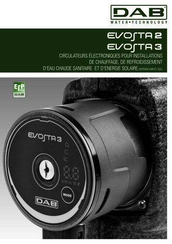
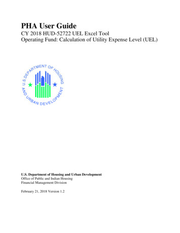
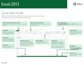
MODEL NUMBER NOMENCLATUREExample of Model Number593Htg. StagesT4TierP5Base Effy.66Major SeriesA7-9Htg. Cap.11 - 12Width1410MotorE04013Voltage--14Minor Series--08 - 800 CFM10 - 1000 CFM12 - 1200 CFM14 - 1400 CFM16 - 1600 CFM18 - 1800 CFM20 - 2000 CFM22 - 2200 CFMFamilyS - Single StageT - Two StageM - ModulatingC - ComfortP - PerformanceN - Infinity0 - 90 AFUE2 - 92 AFUE3 - 93 AFUE5 - 95 AFUE6 - 96 AFUE7 - 97 AFUE14 - 14.2”17 - 17.5”21 - 21.0”24 - 24.5”Major Series15 - 16Airflow10Minor SeriesVoltage040 40,000 BTU060 60,000 BTU S - Standard080 80,000 BTU E - Energy Efficient100 100,000 BTU V - Variable Speed120 120,000 BTU140 140,000 BTUNot all familes have these models.A14368FURNACE COMPONENTSGAS BURNERHOT SURFACEIGNITERMANUAL RESETROLLOUT SWITCHFLAMESENSORMANUAL RESETROLLOUT SWITCHGAS VALVEMAIN LIMIT SWITCH(BEHIND GAS VALVE)OPERATING INSTRUCTIONSNOT SHOWN (LOCATED ONMAIN FURNACE DOOR, SEEOPERATING INSTRUCTIONSINSIDE DOOR FIGURE).INDUCER MOTORASSEMBLYELECTRICAL JUNCTIONBOX (IF REQUIRED,LOCATION MAY VARY)BLOWER DOORSAFETY SWITCHMEDIA CABINETBLOWER ANDMOTORFURNACECONTROLBOARDCAPACITOR/POWER CHOKE(IF USED)RATING PLATE NOT SHOWN(LOCATED ON BLOWER DOOR)REPRESENTATIVE DRAWING ONLY, SOME MODELS MAY VARY IN APPEARANCE.A11408359TP6A1-2Family
SPECIFICATIONSHeating Capacity and EfficiencyHigh HeatInputLow HeatHigh HeatOutputLow HeatCertified TemperatureRise Range ºF (ºC)Airflow Capacity and Blower DataRated External StaticPressure (in. w.c.)59TP6AAirflow Delivery@ Rated ESP (CFM)Cooling Capacity (tons)@ 400, 350 CFM/tonDirect-Drive Motor TypeDirect-Drive Motor HPMotor Full Load AmpsRPM RangeSpeed SelectionsBlower Wheel Dia x Width(BTUH)(BTUH)(BTUH)(BTUH)High HeatLow HeatHeatingCoolingHigh HeatLow HeatCooling400 CFM/ton350 CFM/ton040-10 040-12 060-12 060-14 080-16 080-20 100-20 120-2240,00040,00060,00060,00080,00080,000 100,000 8,00039,00039,00058,00058,00078,00078,00097,000 6,00040 - 70 40 - 70 40 - 70 40 - 70 40 - 70 40 - 70 40 - 70 40 - 70(22 - 39) (22 - 39) (22 - 39) (22 - 39) (22 - 39) (22 - 39) (22 - 39) (22 - 39)30 - 60 30 - 60 30 - 60 30 - 60 30 - 60 30 - 60 30 - 60 30 - 60(17 - 33) (17 - 33) (17 - 33) (17 - 33) (17 - 33) (17 - 33) (17 - 33) (17 - 33)040-100.100.581566090522.51/26.8in.11 x 7Air Filtration SystemFilter Used for Certified Watt DataElectrical DataInput VoltageOperating Voltage RangeMaximum Input AmpsUnit AmpacityMinimum Wire SizeMaximum Wire Length@ Minimum Wire SizeMaximum Fuse/Ckt Bkr(Time-Delay Type Recommended)Transformer Capacity (24vac output)External Control PowerAvailable040-120.100.586066010652.53060-12 060-14 080-16 tronically Communicated Motor (ECM)1/21/23/43/416.86.88.48.410.9600 - 1200Variable (PWM)11 x 811 x 711 x 811 x 811 x 10Optional Media CabinetField Supplied rMinimum Inlet Gas pressure (in. wc)Maximum Inlet Gas pressure (in. wc)Manufactured (Mobile) Home KitIgnition DeviceLimit ControlHeating Blower Control (Heating Off-Delay)Cooling Blower Control (Time Delay Relay)Communication SystemThermostat ConnectionsAccessory .911 x 1011 x (11.0)11.815.61236(11.0)20202040 VA24.3 VA34.6 VAHeatingCoolingControlsGas Connection SizeBurners (Monoport)Gas Valve (Redundant)060-14 0-14 080-16 080-20 100-201/2" - NPT233445White Rodgers4.513.6not approved for MH useSilicon Nitride180165180170200180Adjustable: 90, 120, 150, 180 seconds90 secondsNoneR, W/W1, W2 Y/Y2, Y1, G, Com 24V, DHUMEAC (115vac); HUM (24vac); 1-stg AC (via Y/Y2)* See Accessory List for part numbers available.4060-12120-226160
ACCESSORIESPART NUMBER040--- 10 040--- 12 060--- 12 060--- 14 080--- 16 080--- 20 100--- 20 120--- GACK0101HCKP908 DDDDDDDDDDDDDDDDDDDDDDDDDDDDDDDDDDDSee Venting TablesSee Venting TablesDDDDAll DV HorizontalDDDDDKGAAD0101MEC20”x25” IAQ DevicesKGAAD0201MEC24”x25” IAQ DT6 ---PRH01 2025-A08Use with EZXCAB---1016Use with EZXCAB---1020Use with EZXCAB---1024Use with EZXCAB---1016Use with EZXCAB---1020Use with EZXCAB---1024Use with FILCABXL ---1016Use with FILCABXL ---1020Use with FILCABXL ---1024Up to 1600 CFMUp to 2000 CFMGAPACCCAR1625-A05Use with GAPAAXCC1625GAPACCCAR2025-A05Use with GAPAAXCC2025PGAPXX1625Up to 1600 CFMPGAPXX2025Up to 2000 CFMPGAPAXXCAR1625Use with PGAPXX1625PGAPAXXCAR2025Use with PGAPXX2025559TP6ADESCRIPTIONVenting AccessoriesVent Kit - Through the CabinetVent Terminal - Concentric - 2” (51 mm)Vent Terminal - Concentric - 3” (76 mm)Vent Terminal Bracket - 2” (51 mm)Vent Terminal Bracket - 3” (76 mm)Vent Kit --- Rubber CouplingCondensate Drainage AccessoriesFreeze Protect Kit - Heat TapeCPVC to PVC Drain Adapters - 1/2” CPVC to 3/4” PVCHorizontal Trap Grommet - Direct VentCondensate Neutralizer KitExternal Trap KitDuctwork Adapter AccessoriesFurnace Base Kit for Combustible FloorsCoil Adapter Kits --- No OffsetCoil Adapter Kits --- Single OffsetCoil Adapter Kits --- Double OffsetReturn Air Base (Upflow Applications) 14.0 ---in. wideReturn Air Base (Upflow Applications) 17.5 ---in. wideReturn Air Base (Upflow Applications) 21.0 ---in. wideReturn Air Base (Upflow Applications) 24.5 ---in. wideIAQ Device Duct Adapters 20.0 ---in. IAQ to 16 in. SideReturnIAQ Device Duct Adapters 24.0 ---in. IAQ to 16 in. SideReturnGas Conversion AccessoriesGas Conversion Kit - Nat to LP; Var-speed ProductsGas Conversion Kit - LP to Nat; Var-speed ProductsGas Orifice Kit - #42 (Nat Gas)Gas Orifice Kit - #43 (Nat Gas)Gas Orifice Kit - #44 (Nat Gas)Gas Orifice Kit - #45 (Nat Gas)Gas Orifice Kit - #46 (Nat Gas)Gas Orifice Kit - #47 (Nat Gas)Gas Orifice Kit - #48 (Nat Gas)Gas Orifice Kit - #54 (LP)Gas Orifice Kit - #55 (LP)Gas Orifice Kit - #56 (LP)Gas Orifice Kit - 1.25mm (LP)Gas Orifice Kit - 1.30mm (LP)Control AccessoriesPerformanceR Series EdgeR ThermostatTwinning KitIAQ AccessoriesFilter Pack (6 pack) --- Washable - 16x25x1(406x635x25 mm)Filter Pack (6 pack) --- Washable - 24x25x1(610x635x25 mm)EZ-Flex Filter - 16” (406 mm)EZ-Flex Filter - 20” (508 mm)EZ-Flex Filter - 24” (610 mm)EZ-Flex Filter with End Caps - 16” (406 mm)EZ-Flex Filter with End Caps - 20” (508 mm)EZ-Flex Filter with End Caps - 24” (610 mm)Cartridge Media Filter - 16” (406 mm)Cartridge Media Filter - 20” (508 mm)Cartridge Media Filter - 24” (610 mm)Carrier Infinity Air Purifier - 16x25 (406x635 mm)Carrier Infinity Air Purifier - 20x25 (508x635 mm)Carrier Infinity Air Purifier Repl. Filter- 16x25(406x635 mm)Carrier Infinity Air Purifier Repl. Filter- 20x25(508x635 mm)Carrier Performance Air Purifier - 16x25 (508x635mm)Carrier Performance Air Purifier - 20x25 (508x635mm)Carrier Performance Air Purifier Repl Filter - 16x25(406x635 mm)Carrier Performance Air Purifier Repl. Filter - 20x25(508x635 mm)D Used with the model furnace
AIR DELIVERY - CFMUnit Size040---10Clg Default:59TP6ACooling (SW2)Clg SW2:Heating(SW1)040---12Clg Default:Cooling (SW2)Clg SW2:Heating(SW1)060---12Clg Default:Cooling (SW2)Clg SW2:Heating(SW1)(SW1-5 and SW2---2 set to OFF, except as indicated. See notes 1 and 2)Cooling Switch SettingsExternal Static Pressure ON615555510475440395355270230note NON112510801020970905855805755700635Maximum Clg Airflow 2112510801020970905855805755700635High Heat Airflow 3815770725695660625595550510475Low Heat Airflow 3660605560530495450415340300Note 915860810Maximum Clg Airflow 2125012101165111510651015965915860810High Heat Airflow 3860825785745705670630595565525Low Heat Airflow 3650595545500460415365320275note 71015955895815745See note 4See note N125012101165111510651015955895815745Maximum Clg Airflow 2125012101165111510651015955895815745High Heat Airflow 311251100107010451010980925875820740Low Heat Airflow 39008658358007607206906506105806See note 4See note 4
Unit Size060---14Clg Default:Cooling (SW2)Clg SW2:Heating(SW1)080---16Clg Default:Cooling (SW2)Clg SW2:Heating(SW1)080-- 20Clg Default:Cooling (SW2)Clg SW2:Heating(SW1)Cooling Switch SettingsSW2-8SW2-7SW2-60.10.20.3External Static Pressure e note 4OFFONOFF780725660615540See note 514151340127512001105Maximum Clg Airflow 21705165015951545147514151340127512001105High Heat Airflow 31145110510751030995955905870825785Low Heat Airflow ON1805176517201665161015401475140013151235Maximum Clg Airflow 21805176517201665161015401475140013151235High Heat Airflow 31520149014551420138513551320128512201155Low Heat Airflow 60See note 8See note 151820173016401525Maximum Clg Airflow 22290223021602085200519151820173016401525High Heat Airflow 31575153514851445140013501310126012151170Low Heat Airflow 312301170112510651015955900855795755NOTE: See notes at end of table.7See note 4See note 459TP6AAIR DELIVERY -- CFM (CONTINUED)
AIR DELIVERY -- CFM (CONTINUED)Unit Size100-- 20Clg Default:59TP6ACooling (SW2)Clg SW2:Heating(SW1)120-- 22Clg Default:Cooling (SW2)Clg SW2:Heating(SW1)Cooling Switch SettingsSW2-8SW2-7SW2-60.10.20.3External Static Pressure 016401525Maximum Clg Airflow 22290223021602085200519151820173016401525High Heat Airflow 31905186518251775173016851640159015451490Low Heat Airflow 64515651480See note 4See note 0480See note 4OFFONOFF1075975915835765See note 4OFFONON1205113510551000935See note 2010196019101850180017501690164515651480ONONONnote 8237523002205211520101890175016451550Maximum Clg Airflow 2note 8237523002205211520101890175016451550High Heat Airflow 3note 8237523002205211520101890175016451550Low Heat Airflow 317351675162515601500145513951345128512251. Nominal 350 CFM/ton cooling airflow is delivered with SW1 ---5 and SW2 ---2 set to OFF.Set both SW1 ---5 and SW2 ---2 to ON for 7% airflow (nominal 370 CFM/ton).Set SW1 ---5 to ON and SW2 ---2 to OFF for 15% airflow (nominal 400 CFM/ton).Set SW2 ---2 to ON and SW1 ---5 to OFF for ---7% airflow (nominal 325 CFM/ton).The above adjustments in airflow are subject to motor horsepower range/capacity.2. Maximum cooling airflow is achieved when switches SW2 ---6, SW2 ---7, SW2 ---8 and SW1 ---5 are set to ON, and SW2 ---2 is set to OFF.3. All heating CFM’s are when low heat rise adjustment switch (SW1 ---3) and comfort/efficiency adjustment switch (SW1 ---4) are both set to OFF.4. Ductwork must be sized for high ---heating CFM within the operational range of ESP. Operation within the blank areas of the chart is not recommendedbecause high ---heat operation will be above 1.0 ESP.5. All airflows of 1880 CFM or less on 21” and 24.5” casing size furnaces are 5% less on side return only installations.6. Return air above 1800 CFM on 24.5” casing requires two sides, one side and bottom, or bottom only to allow sufficient airflow to the furnace.7. For upflow applications, air entering from one side into both the side of the furnace and a return air base counts as a side and bottom return.8. Airflow not stable at this ESP.8
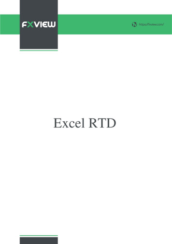
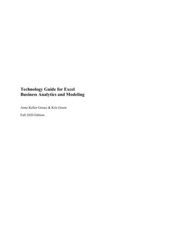
MAXIMUM EQUIVALENT VENT LENGTH - FT. (M)NOTE: Maximum Equivalent Vent Length (MEVL) includes standard and concentric vent termination and does NOT include elbows.Use Table 2 - Deductions from Maximum Equivalent Vent Length to determine allowable vent length for each application.Table 1 – Maximum Equivalent Vent Length -- Ft. (M)0 to 4500 Ft. (0 to 1370 M) Altitude0 to 2000(0 to 610)2001 to 3000(610 to 914)3001 to 4000(914 to 1219)4001 to 4500(1219 to 1370)Unit SizeBTU/Hr40,000 360,00080,000100,000120,000140,000 440,00060,00080,000100,000120,000140,000 440,00060,00080,000100,000120,000140,000 440,00060,00080,000100,000120,000140,000 6)(11.0)(6.4)(4.3)DIRECT VENT (2-PIPE) AND NON-DIRECT VENT (1-PIPE)Vent Pipe Diameter (in.) 122-1/23210(64.0)250(76.2)NA TES: See notes at end of venting tables.See Table 3 for altitudes over 4500 ft. (1370 M)VENT TERMINAL CONFIGURATIONSELBOW CONFIGURATIONSConcentricLongMediumMiteredStandard 2-in., 3-in., oroptional 4-in. termination.A13110Table 2 – Deductions from Maximum Equivalent Vent Length -- Ft. (M)Pipe Diameter (in):Mitered 90º ElbowMedium Radius 90º ElbowLong Radius 90º ElbowMitered 45º ElbowMedium Radius 45º ElbowLong Radius 45º ElbowTeeConcentric Vent TerminationStandard Vent NA0(0.0)59TP6AAltitudeFT (M)
Venting System Length CalculationsThe Total Equivalent Vent Length (TEVL) for EACH combustion air or vent pipe equals the length of the venting system, plus the equivalentlength of elbows used in the venting system from Table 2.Standard vent terminations or factory accessory concentric vent terminations count for zero deduction.See vent system manufacturer’s data for equivalent lengths of flexible vent pipe or other termination systems. DO NOT ASSUME that onefoot of flexible vent pipe equals one foot of straight PVC/ABS DWV vent pipe.Compare the Total Equivalent Vent Length to the Maximum Equivalent Vent Lengths in Tables 1 and 3.Example 159TP6AA direct--vent 60,000 Btuh furnace installed at 2100 ft. (640 M). Venting system includes, FOR EACH PIPE, 100 feet (30 M) of vent pipe,95 feet (28 M) of combustion air inlet pipe, (3) 90 long radius elbows, (2) 45 long radius elbows and a factory accessory concentric ventkit.Can this application use 2--in. (50 mm ND) PVC/ABS DWV vent piping?Measure the required linear length of air inlet and vent pipe; insert thelongest of the two here:Add equiv length of (3) 90º long-radius elbows(use the highest number of elbows for either the3x3 ftvent or inlet pipe)Add equiv length of (2) 45º long-radius elbows(use the highest number of elbows for either the2x1.5 ftvent or inlet pipe)Add equiv length of vent termination100 ftUse length of the longer of the ventor air inlet piping system 9 ft.From Table 2 3 ft.From Table 20 ft.Total Equivalent Vent Length (TEVL)112 ft.From Table 2From Vent Manufacturer’s instructions;zero for PVC/ABS DWVAdd all of the above linesMaximum Equivalent Vent Length (MEVL)Is TEVL less than MEVL?127 ft.YESFor 2” pipe from Table 1Therefore, 2” pipe may be usedAdd correction for flexible vent pipe, if any0 ft.Example 2A direct--vent 60,000 Btuh furnace installed at 2100 ft. (640 M) Venting system includes, FOR EACH PIPE, 100 feet (30 M) of vent pipe,95 feet (28 M) of combustion air inlet pipe, (3) 90 long radius elbows, and a polypropylene concentric vent kit. Also includes 20 feet (6 M)of flexible polypropylene vent pipe, included within the 100 feet (30 M) of vent pipe.Assume that one meter of flexible 60 mm or 80 mm polypropylene pipe equals 1.8 meters of PVC/ABS pipe. VERIFY FROM VENTMANUFACTURER’S INSTRUCTIONS.Can this application use 60 mm (O.D.) polypropylene vent piping? If not what size piping can be used?Measure the required linear length of air inlet and vent pipe; insert thelongest of the two here:Add equiv length of (3) 90º long-radius elbows(use the highest number of elbows for either the3x3 ftvent or inlet pipe)Add equiv length of (2) 45º long-radius elbows(use the highest number of elbows for either the0xvent or inlet pipe)Add equiv length of vent termination9Mx 3 ft/MAdd correction for flexible vent pipe, if any1.8x20 ftTotal Equivalent Vent Length (TEVL)100 ftMaximum Equivalent Vent Length (MEVL)Is TEVL less than MEVL? 9 ft.From Vent Manufacturer’s instructions 0 ft.From Vent Manufacturer’s instructions 18 ft.36 ft.163 ft.From Vent Manufacturer’s instructionsFrom Vent Manufacturer’s instructionsAdd all of the above lines127 ft.For 2” pipe from Table 1Therefore, 60mm pipe may NOT be used;try 80 mmNOMaximum Equivalent Vent Length (MEVL)Is TEVL less than MEVL?250 ft.YES10Use length of the longer of the ventor air inlet piping systemFor 3” pipe from Table 1Therefore, 80 mm pipe may be used
MAXIMUM EQUIVALENT VENT LENGTH - FT. (M) (CONTINUED)NOTE: Maximum Equivalent Vent Length (MEVL) includes standard and concentric vent termination and does NOT include elbows.Use Table 2 - Deductions from Maximum Equivalent Vent Length to determine allowable vent length for each application.Table 3 – Maximum Equivalent Vent Length -- Ft. (M)4501 to 10,000 Ft. (1371 to 3048 M) Altitude4501 to 5000(1370 to 1524)5001 to 6000(1524 to 1829)6001 to 7000(1829 to 2134)7001 to 8000(2134 to 2438)8001 to 9000(2438 to 2743)9001 to 10,000(2743 to 3048)DIRECT VENT (2-PIPE) AND SINGLE-PIPEVent Pipe Diameter (in.) 122-1/23Unit 000100,000120,000140,000 440,00060,00080,000100,000120,000140,000 440,00060,00080,000100,000120,000140,000 440,00060,00080,000100,000120,000140,000 440,00060,00080,000100,000120,000140,000 440,00060,00080,000100,000120,000140,000 42013NANANA271611NANANA2113NANANAN
S Certified to leak 2% or less of nominal air conditioning CFM delivered when pressurized to 1--in. water column with all . conversion kit is required to convert furnace for use with propane gas. The efficiency is AHRI efficiency rating certified. . 080 80,000 BTU 100 100,000 BTU 120 120,000 BTU 140 140,000 BTU Not all familes have these .