Transcription
Green Infrastructure forSingle Family ResidencesCITY OF ATLANTA STORMWATER GUIDELINESPrepared forCITY OF ATLANTA, GEORGIADEPARTMENT OF WATERSHED MANAGEMENTNOVEMBER 2012Prepared byAMEC Environment & Infrastructure
City of Atlanta, GeorgiaResidential Green PracticesTHIS PAGE INTENTIONALLY LEFT BLANKCity of Atlanta – Residential Green Practices
City of Atlanta, GeorgiaResidential Green PracticesINTRODUCTIONBackground and PurposeLand development permanently alters the way in which stormwater flows across a site due to grading,compaction, and the installation of impervious cover. In order to mitigate these impacts, the City ofAtlanta requires, in accordance with Chapter 74, Article X. Post Development StormwaterManagement, that stormwater management measures be utilized when constructing a new home oran addition that is greater than 1,000 square feet of impervious surface.The purpose of this document is to provide a guideline for selecting and installing the appropriatestormwater management measures when constructing a home.This guideline employs simplified design standards more applicable to the homeowner/builderexperience, thus avoiding the necessity for complex engineering calculations and analysis. Thisguideline is meant to complement the use of the Georgia Stormwater Management Manual (BlueBook) and the Coastal Stormwater Supplement (CSS). Those documents may be used for designpurposes as appropriate in lieu of this document, but must be used for sites that propose more than5,000 square feet of impervious area.Submittal InformationThe following section provides, in a question and answer format, the necessary information forunderstanding the requirements and process for submittal.What types of Single Family Residential (SFR) projects require Stormwater Management?The following activities are required to install stormwater management on site: The construction of a new or infill house; orAdditions that involve the creation, or demolition and replacement of more than 1,000 ft2 ofimpervious cover.What portions of SFR projects require Stormwater Management?These requirements are intended to capture the main portions of SFR impervious areas.Impervious cover is defined as a surface composed of any material that significantly impedes orprevents the natural percolation of water into soil, which includes, but is not limited to, rooftops,buildings, streets and roads, and any concrete or asphalt surface. Only the major impervious areas ofthe property need to be treated. This includes the rooftop of the main structure and garage, parkingareas and paved patio areas. It excludes minor out buildings, walkways, small miscellaneous pavedareas, and the entry driveway area leading from the road to parking and turn around areas.The area draining to any practice is called the “contributing drainage area” and normally consists of100% impervious area, though for rain gardens and filter strips incidental small pervious areas can beincluded if unavoidable, and the areas are stabilized to eliminate soil erosion.City of Atlanta – Residential Green Practices1
City of Atlanta, GeorgiaResidential Green PracticesWhat are the principles for managing stormwater on SFR developments?Residential developments are not required to provide the same types of stormwater management ascommercial projects; however, certain requirements must be met to ensure that stormwater runoffdoes not overwhelm stormwater infrastructure; impact water quality in our streams; or impactadjacent property. The key principles for managing stormwater from a SFR lot are: Proper grading techniques and Erosion Control BMPs during construction;Runoff Reduction (see section below);Reliance on infiltration only where the water table or bedrock layer is at least two feet belowthe bottom of the practice in use; and,Proper installation and maintenance of downspouts, channels, or any other sources ofconcentrated flow.What is Runoff Reduction?The term ‘Runoff Reduction’ means the interception, evapotranspiration, infiltration or capture andreuse of stormwater runoff. Examples of runoff reduction techniques on a single family residentialdevelopment include any appropriate combination of the following techniques termed GreenInfrastructure Practices:1.2.3.4.5.6.installing a rain garden or bioretention area,replacing traditionally impervious surfaces (driveways, patios, etc.) with pervious paving,routing downspouts to underground dry wells,routing downspouts to modified French drains,using cisterns for reuse or irrigation, ordirecting sheet flow to adequately sized vegetated filter strips, or any appropriate combinationof techniques.The goal of these techniques is to reduce the volume of runoff generated by the first one-inch of rain.Other Green Infrastructure Practices that employ runoff reduction techniques may be used in lieu ofthese techniques with proper documentation of design criteria and details.How are Runoff Reduction techniques sized on SFR developments?Applicants have the choice to meet this requirement by following the practices in this technicalguidance document or by utilizing the Blue Book and the CSS to design an appropriate stormwatermanagement plan. The amount of volume to be reduced on site is directly related to the drainagearea contributing runoff to the treatment technology.What needs to be submitted?Applicants must develop a site plan using the checklist found at http://www.atlantaga.gov/. Thechecklist items relevant to stormwater management include the following: Existing and proposed ground contours and elevations;Sanitary and storm sewer, structures and easements;City of Atlanta – Residential Green Practices2
City of Atlanta, GeorgiaResidential Green Practices Location, configuration and finished floor elevations for existing and proposed buildingstructures;Location, configuration and finished elevations for existing and proposed paved areas;Erosion and sediment control practices in conformance with the Manual for Erosion andSediment Control in Georgia, Chapter 6; andPertinent to stormwater the following guidance applies to all designs: Stormwater runoff from the first one inch of rainfall must be captured on site and dissipatedthrough the use of infiltration, evapotranspiration or alternate use (e.g. irrigation). It cannot runoff the site.Concentrated stormwater discharge from a downspout, cistern, or any collection device shallbe located a distance of no less than 10 feet from any common property line.Details of all Green Infrastructure Practices shall be attached to the site plan using, wherepossible, specification sheets from this document or sets of plans of equal detail and coverage.What is in the rest of this document?The remainder of the document contains:(1) A set of six information/specification sheets, one for each of the six Green InfrastructureControls recommended for use. For each the last two pages are a tear-off set of specificationsthat can be filled in and stapled to construction plans.(2) An Appendix that describes how to conduct infiltration testing.(3) An Appendix that describes the types of vegetation recommended for use for those Controlsthat feature vegetation as part of the treatment approach.City of Atlanta – Residential Green Practices3
City of Atlanta, GeorgiaResidential Green PracticesTHIS PAGE INTENTIONALLY LEFT BLANKCity of Atlanta – Residential Green Practices
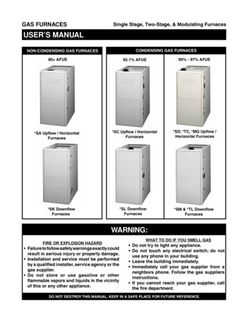
CISTERNSINGLE FAMILY RESIDENTIAL GUIDECITY OF ATLANTA, GEORGIADEPARTMENT OF WATERSHED MANAGEMENTCisterns are low impact development practicesthat store rainwater for later use. Rain iscollected from a downspout system, screened toremove trash and leaves and conveyed to astorage container for subsequent use. Unless anadvanced filtration system is used, water stored inthe cistern is for non-potable water use only. Ifproperly sized, they can provide significantreductions in stormwater runoff rates, volumesand pollutant loads from residential sites. Rainbarrels may be part of an overall stormwatermanagement system; however, by themselvesthey may not be sufficient to meet therequirements of this ordinance.1,500 Gallon CisternSource: LID Urban Design ToolsLocation Consider the size of the contributing drainage areas, and projected water needs, to determine howlarge a storage tank is needed. Cisterns should drain only impervious areas – preferably rooftops.Pick a location keeping in mind: (1) ease in connecting roof drains, (2) overflow to downslopeareas, (3) level area, (4) location relative to intended water uses, (5) other utility conflicts, (6)electrical connections if applicable, (7) residential emergency ingress/egress, (8) leaf screen option,(9) location of hoses or other water distribution components, and (10) aesthetic considerations.Design To fully meet the Atlanta standard, cistern capacity must be designed for a 1 inch storm. A goodrule of thumb is that when sizing a cistern for the one inch rain standard, each square foot ofrooftop will contribute 0.6 gallons of runoff. A one-hundred square foot roof surface will fill a 55gallon barrel.Cisterns come in sizes from a 55 gallon rain barrel to a 1,500 gallon cistern. If the cistern cannothold the full inch one alternative is to divert overflow to another low impact developmentstructure such as a filter strip, or rain garden.Measure contributing roof area width from the drip line of the overhang to the roof peak ignoringthe slant, and the length. The width times the length in feet is the drainage area. Multiply that by0.6 gallons and that is the size of the cistern you will need to fully meet the one-inch rainfallstandard.All holding tanks should be opaque to prevent algae growth.
Pretreatment of water entering the cistern will remove debris, dust, leaves, and other material.Pretreatment options are illustrated on the specification sheet. One or more options should bechosen.Example In-Line Screen - Leaf Beater by Rain Harvest Systems Example Rain BarrelThe cistern should have an overflow pipe so that when the tank reaches capacity, the rainwaterwill be directed away from adjacent buildings. More than one cistern can be linked to increasestorage capacity.Drainage system components leading to the cistern should have a minimum slope of 2% for gravitydrainage to the cistern.For more complex designs a rainwater harvesting model is provided by the North Carolina StateUniversity at ity feed drip irrigation kits are available from several suppliers as well as complete instructionson how to design an irrigation system for the low pressure of a cistern system without a pump.Maintain To maintain the storage capacity of thecistern rainwater should be used regularlyand a draw down plan initiated.Routine checks of the intake and leafscreening components should be done oncein the spring and periodically during the fall ifleaves fall on the contributing roof area.Insure mosquito screen is tight.Inspect and if necessary clean out tankannually by scrubbing and letting water drainthrough low flow plug.Check connections for leaks; and inspectoverflow for erosion.Example Linked CisternsSource: http://www.djc.com
TYPICAL COMPONENTS (ATTACH MANUFACTURER’S SPECIFICATIONS)CONSTRUCTION STEPS:1. Locate cistern for: (1) ease in connecting roof drains, (2) overflow to downslope area, (3) levelarea, (4) location relative to intended water uses, (5) other utility conflicts, (6) electricalconnections if applicable, (7) emergency ingress/egress, (8) leaf screen option, (9) location ofhoses or other water distribution components, and (10) aesthetic considerations.2. Depending on use review and follow applicable plumbing code.3. Provide level foundation of compacted earth, blocks, gravel or other hard long lasting surface.4. Place cistern tank and review all connections for layout and sizing.5. Cut and route downspouts or other rainwater delivery components, leaf screen option(s)chosen (circle selected options inPretreatment Options Detail figure), andmosquito screen as applicable. Strap andsupport as needed.6. Install water outlet connections includingpumps as applicable. Follow manufacturer’sspecification for all connections and fittingsincluding inlet, overflow, and clean out.7. Extend overflow to adequate non-erodingdischarge point no less than 10 feet from anycommon property line.8. Test cistern by filling with water and testingall components in turn – including sprayingwater on the roof and observing flow.9. Consider appearance and final landscapingand screening. Complete construction,landscaping, etc.NAME/ADDRESS:CITY OF ATLANTADEPARTMENT OFWATERSHED MANAGEMENTCISTERNSPECIFICATIONSPAGE 1 OF 2November 2012
SKETCH LAYOUTPROVIDE PLAN AND ELEVATION VIEWS OF CISTERN AND HOUSE SHOWING ROOF AREA DIRECTED TOCISTERN AND KEY DIMENSIONS AND CONNECTIONS AND OVERFLOW RELATIVE TO PROPERTY LINE.NOTES:1. ATTACH MANUFACTURER’S SPECIFICATIONS AND OTHER DETAILSSIZING CALCULATION:0.6 GALLONS * SQ FT OF ROOF AREA DIRECTED TO CISTERN)ROOF AREA DIRECTED TO CISTERN SQ FTCISTERN SIZE GALTYPE OF CISTERN/MANUFACTURER:CITY OF ATLANTADEPARTMENT OFWATERSHED MANAGEMENTMAINTENANCE:1. TO MAINTAIN THE STORAGE CAPACITYOF THE CISTERN RAINWATER SHOULDBE USED REGULARLY2. ROUTINE CHECKS OF THE INTAKE ANDLEAF SCREENING COMPONENTSSHOULD BE DONE ONCE IN THESPRING AND PERIODICALLY DURINGTHE FALL IF LEAVES FALL ON THECONTRIBUTING ROOF AREA.3. INSPECT AND IF NECESSARY CLEANOUT TANK ANNUALLY BY SCRUBBINGAND LETTING WATER DRAIN THROUGHLOW FLOW PLUG. CHECKCONNECTIONS FOR LEAKS; ANDINSPECT OVERFLOW FOR EROSION.ATTACH THIS TWO-PAGESPECIFICATION TO HOUSE PLANSUBMITTALCISTERNSPECIFICATIONSPAGE 2 OF 2November 2012
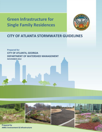
DRY WELLSINGLE FAMILY RESIDENTIAL GUIDECITY OF ATLANTA, GEORGIADEPARTMENT OF WATERSHED MANAGEMENTDry wells are comprised of seepage tanks set in the ground and, inAtlanta’s tight soils, surrounded with stone that are designed tointercept and temporarily store stormwater runoff until it infiltratesinto the soil. Alternately the pit can be filled with stone with waterentering via a perforated pipe with a perforated standpipe in placeof the tank.Dry wells are particularly well suited to receive rooftop runoffentering the tank via an inlet grate (shown right) or directdownspout connection (below right). When properly sized and laidout dry wells can provide significant reductions in stormwater runoffand pollutant loads.Source: www.earthcontactproducts.com/Location Dry wells must be located at least 10 feet from buildingfoundations and 10 feet from property lines.To reduce the chance of clogging, dry wells should drain onlyimpervious areas, and runoff should be pretreated with at leastone of the leaf removal options to remove debris and largerparticles.The height of the tank should not exceed 45 inches unlessinfiltration testing has been done to insure a drain time of 72hours or less.Dry wells should be located in a lawn or other pervious(unpaved) area and should be designed so that the top of the dry well is located as close to the surfaceas possible.Dry wells should not be located: (1) beneath an impervious (paved) surface; (2) above an area with awater table or bedrock less than two feet below the trench bottom; (3) over other utility lines; or, (4)above a septic field. Always call 811 to locate utility lines before you dig.Construction Consider the drainage area size and the soil infiltration rate when determining the size of the dry well,(see table on next page).The sides of the excavation should be trimmed of all large roots that will hamper the installation of thepermeable drainage fabric used to line the sides and top of the dry well.The dry well hole should be excavated 1 foot deeper and two feet larger in diameter than the well toallow for a 12 inch stone fill jacket.
The native soils along the bottom of the dry well should be scarified or tilled to a depth of 3 to 4 inches.Fill below and around dry well approximately 12 inches ofclean, washed #57 stone. #57 stone averages ½ inch to 11/2 inches.Fill the final 6 inches of the excavation with native soil.Optionally pea gravel or #8 stone can be carried to thesurface.For rooftop runoff, install a leaf screen in the gutter ordown spout prior to entering the dry well to preventleaves and other large debris from clogging the dry well.For non-rooftop runoff, precede dry well with an in groundsump grate inlet leaf trap.An overflow, such as a vegetated filter strip or grassSource: nancysteele.files.wordpress.comchannel, should be designed to convey the stormwaterrunoff generated by larger storm events safely bypassing the dry well.The optional design involves placement of a vertical standpipe connected to the inlet pipe. See figurebelow.The table below can be used to size a dry well system. Given the tank height and diameter the contributingdrainage area in square feet treated can be read. So, for example, if a 10 by 50 foot roof is to be treated thetotal roof area is 20*50 500 square feet. This could be handled by one tank 60” high, 30” diameter. It canalso be handled by two tanks 30” high and 24” in diameter.If you elect to measure infiltration rate and find it is higher than 0.5 in/hr length of the dry well size can bereduced. For every 0.5 in/hr increase in measured infiltration rate above 0.5 in/hr subtract ten percent of therequired dry well size as measured in square feet captured.
Vegetation The landscaped area above the surface of a dry well should be covered with pea gravel when waterenters a dry well through surface features rather than the pipe. This pea gravel layer provides sedimentremoval and additional pretreatment upstream of the dry well and can be easily removed and replacedwhen it becomes clogged.Alternatively, a dry well may be covered with an engineered soil mix, and planted with managed turf orother herbaceous vegetation.MaintenanceAnnual maintenance is important for dry wells, particularly in terms of ensuring that they continue to providemeasurable stormwater management benefits over time. Inspect gutters and downspouts removing accumulated leaves and debris. Inspect dry well following rainfall events. If applicable, inspect pretreatment devices for sediment accumulation. Remove accumulated trash anddebris. Inspect top layer of filter fabric for sediment accumulation. Remove and replace if clogged.
THIS PAGE INTENTIONALLY LEFT BLANK
TYPICAL COMPONENTS (ATTACH MANUFACTURER’S SPECIFICATIONS)CONSTRUCTION STEPS:1. Review potential dry well areas and layout. Dry wells should not be located: (1) beneath an impervious(paved) surface; (2) above an area with a water table or bedrock less than two feet below the trenchbottom; (3) over other utility lines; or, (4) above a septic field. Insure outlet daylights at least ten feetfrom property line.2. Measure the area draining to the dry well and determine required size from the table on the next page.3. If soil is a concern perform infiltration test according to Appendix A. If the rate is less than 0.25 in/hrthis method cannot be used. If the rate is more than 0.50 in/hr the storage volume may be decreased10% for every 0.50 in/hr infiltration rate increase above 0.50 in/hr.4. Measure elevations and dig the hole to the required dimensions. Scarify the bottom soil surface 3”.5. Place and tamp 6” to 12” of #57 gravel in bottom. Pea gravel can be substituted for leveling purposesin the upper three inch layer below the tank.6. Place and secure filter cloth down sides of theexcavation leaving enough to fold over the top belowthe soil and turf.7. Place tank and install piping. Bond top of tank in place.8. Cut and route downspouts or other rainwater deliverycomponents, leaf screen option(s) chosen (circleselected options in Pretreatment Options Detail figure).Strap and support as needed.9. Create a safe overflow at least 10 feet from yourproperty edge and insure it is protected from erosion.10. Test connections with water flow
Atlanta requires, in accordance withChapter 74, Article X. Post Development Stormwater Management, that stormwater management measures be utilized when constructing a new home or an addition that is greater than 1,000 square feet of impervious surface.