Transcription
V1.10TBS09S ModbusMasterModbus Master to SDI 12 Slave ConverterThe TBS09S is a converter to connect SDI-12 sensors to a Modbus master. It can control multipleSDI12 sensors in parallel by individually addressing the connected SDI-12 sensors.TBS09S Modbus Master to SDI 12 Slave ConverterFeatures Modbus Master to SDI 12 Slave Converter Multiple SDI-12 sensors can be connected SDI-12 Standard V1.3 Modbus RTU, 19200 baud Switched sensor supply voltage output 5 - 16V supply voltage 6mA current consumption when active 20µA in idle, 4mA in active mode Operating Temperature Range:- 40 C 80 CTarget Applications SDI-12 sensor networks with Modbuscontroller 2021 Tekbox Digital SolutionsFactory 4, F5, Lot I-3B-1, Saigon HiTech Park, Q.9 Ho Chi Minh City Tel 84 287 1099865 office@tekbox.com www.tekbox.com
V1.10TBS09SModbus Master to SDI-12 Slave ConverterContents1INTRODUCTION32PRODUCT SPECIFICATION33CALIBRATION AND SETTINGS44CONNECTIONS55SENDING SDI-12 COMMANDS THROUGH TBS09S65.1SUPPORTED SDI-12 COMMANDS65.2MODBUS DEFAULT CONFIGURATION AND FRAMES FORMAT75.2.1Default configuration75.2.2Modbus master to TBS09S: Modbus request format75.2.3TBS09S to Modbus master: Modbus response format75.3TBS09S MODBUS REGISTERS MAPPING85.4TBS09S MODBUS REQUESTS DETAILED DESCRIPTION105.4.1Modbus slave address change105.4.2Query sensor’s SDI-12 address (SDI-12 command: ?!)115.4.3Change sensor’s SDI-12 address (SDI-12 command: aAb!)125.4.4SDI-12 Measurement (SDI-12 commands: aM!/aMC!/aMx!/aMCx!/aC!/aCC!/aCCx!)125.5TBS09S / SDI-12 SENSOR COMMUNICATION FLOW EXAMPLE156SDI-12167HISTORY162
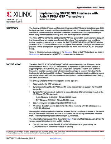
V1.10TBS09SModbus Master to SDI-12 Slave Converter1 IntroductionThe TBS09S is a converter to connect one or multiple SDI-12 sensors to a Modbus device such as a data loggeror telemetry unit. The converter is inserted in between the data logger or RTU with Modbus interface and thesensor(s) with SDI-12 interface. The designation Modbus Master to SDI-12 Slave is ambiguous. Looking purelyat the converter, the device got a Modbus slave interface on one side and a SDI-12 master output at the otherside. However looking at its application, the device is a converter between a Modbus master (data logger, RTU,etc.) and a SDI-12 slave (sensor with SDI-12 interface).The following diagrams describe a typical use of TBS09S module that bridges a Modbus telemetry unit with aSDI-12 sensor and highlight how the internal TBS09S Modbus/SDI-12 layers interact with them.TBS09S application2 Product specification Application: converter used to interface Modbus master devices (eg RTU) with SDI-12 slave devices (egsensors)o The converter embeds a Modbus slave and a SDI-12 master modules SDI-12 compatibility:o Version: v1.3o SDI-12 commands not supported: aI!, a!, aV!, aRx!, aRCx!o Data command supports up to 10 measurements maximum Modbus compatibility:3
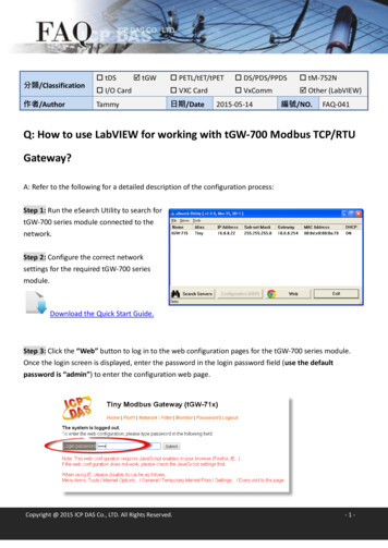
V1.10TBS09SModbus Master to SDI-12 Slave ConverterooooModbus RTUBaud rate: 19200Half or full duplex (configurable)120 Ω termination (configurable) Supply voltage: 5 – 16 V Power consumptiono Active mode: 4 mAo Idle mode: 20µA Form factor: DINRAIL3 Calibration and settingsTBS09S doesn’t require any calibration.It comes factory-configured to operate by default in half duplex with termination.This configuration can be changed by the user by setting related jumpers J3/J4/J5 after lifting the housing:Communication mode:ConfigurationHalf DuplexJ3 Full Duplex Modbus termination:Configuration120 Ω terminationNo terminationJ4 – J5 4
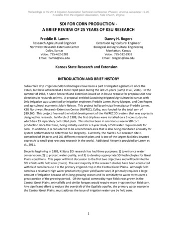
V1.10TBS09SModbus Master to SDI-12 Slave Converter4 ConnectionsTBS09S provides one 4 slots connector (SDI-12) and one 6 slots connector (RS485):SDI-12 terminal assignment, from top to bottom:Slot nameDescriptionCommentShieldCable shieldConnect to sensor’scable shieldGroundGroundConnect to groundSDI-12 data lineConnect to SDI-12sensor data lineConnect to 12V externalpower supplyDataPower*TBS09S supply voltageinputRS485 terminal assignment, from top to bottom:Slot nameDescriptionCommentT TXD outputConnect to Modbusmaster RXD T-TXD- outputR RXD inputConnect to Modbusmaster RXDConnect to Modbusmaster TXD (fullduplex operation only –must be leftunconnected in halfduplex)R-RXD- inputConnect to Modbusmaster TXD- (full duplexoperation only – must5
V1.10TBS09SModbus Master to SDI-12 Slave Converterbe left unconnected inhalf duplex)GGroundConnect to groundP*SDI-12 sensor supplyvoltage output ( 12V,connected to theconverter supply linethrough a high side FETswitch)Connect to SDI-12sensor power line.*The crossed connectivity is caused by the same converter hardware being used for both the Modbus master toSDI-12 slave converter and the SDI-12 master to Modbus slave converter. This is subject to being changed in afuture hardware revision.5 Sending SDI-12 commands through TBS09SSDI-12 commands are encapsulated by Modbus which acts as a communication layer.Executing a SDI-12 command over Modbus requires sending 2 Modbus requests: One request with function code 6 to send the SDI-12 command One request with function code 4 to get the result of the executed SDI-12 command.5.1 Supported SDI-12 commandsTBS09S supports only a subset of SDI-12 commands vs SDI-12 v1.3 specification and has a limitation with respectto Send Data command.The following commands are supported:Address QueryChange AddressStart MeasurementStart Measurement and Request CRCAdditional MeasurementsAdditional Measurements and Request CRCStart Concurrent MeasurementStart Concurrent Measurement and Request CRCAdditional Concurrent MeasurementsAdditional Concurrent Measurements and Request CRCSend Data (*)?!aAb!aM!aMC!aM1! aM9!aMC1! . aMC9!aC!aCC!aC1! aC9!aCC1! . aCC9!aD0! aD9!Supported SDI-12 address range is aligned with SDI-12 v1.3 specification: 0–96
V1.10TBS09SModbus Master to SDI-12 Slave Converter a–z A–Z(*): Send Data aD0!.aD9! supports only up to 10 measurements irrespective of the maximum number ofcharacters that can be returned (75 for a concurrent measurement command, 35 otherwise).5.2 Modbus default configuration and frames format5.2.1 Default configurationTBS09S uses following Modbus configuration: Protocol: Modbus RTU Baud rate: 19200, Parity: none Modbus slave address: 1 (default). It is configurable via Modbus Address Change request within 0x010xFF range5.2.2 Modbus master to TBS09S: Modbus request formatAll Modbus requests sent by the Modbus master (Modbus data logger, Modbus RTU) to TBS09S must beformatted as described in following table as per Modbus specification.Each field represents one byte in hexadecimal:Modbus Master requestSlave AddressFunctionStarting Address HiStarting Address LoData HiData LoError Check Lo (CRC)Error Check Hi (CRC)TBS09S uses only Modbus requests with function codes 4 or 6 depending on the command’s purpose.The CRC must be calculated as per Modbus RTU standard (please note the less significant CRC byte is storedfirst and followed by the most significant CRC byte).Online calculators can be used for this, like on and selectinghexadecimal input type.5.2.3 TBS09S to Modbus master: Modbus response formatEach field in below tables represents one byte.Generic response to a Modbus request with function code 47
V1.10TBS09SModbus Master to SDI-12 Slave ConverterModbus Slave response(TBS09S)Slave Address(TBS09S Modbus address)04Byte Count(2*N, N is the number of InputRegisters)Input Register 1 HiInput Register 1 Lo Input Register N HiInput Register N LoError Check Lo (CRC)Error Check Hi (CRC)Generic response to a Modbus request with function code 6Modbus Slave response(TBS09S)Slave Address(TBS09S Modbus address)06Register Address HiRegister Address LoRegister Value HiRegister Value LoError Check Lo (CRC)Error Check Hi (CRC)Note: in this case, the response is the mirror of the corresponding request.5.3 TBS09S Modbus registers mappingAll available SDI-12 commands that can be sent over Modbus are mapped over a set of registers.The following table lists all TBS09S Modbus registers with their associated commands (‘a’ refers to SDI-12 addressas per SDI-12 standard and is subsequently used as is in this document):Register AddressCommandDescriptionModbus configuration commands0xB000Modbus slave address changeChange TBS09S Modbus addressSDI-12 commands0xA000?!Address Query command0xA100aAb!Change Address command0x0010aM!Start Measurement0x0011aM1!Additional Measurements0x0012aM2!Additional Measurements8
V1.10TBS09SModbus Master to SDI-12 Slave Converter0x0013aM3!Additional Measurements0x0014aM4!Additional Measurements0x0015aM5!Additional Measurements0x0016aM6!Additional Measurements0x0017aM7!Additional Measurements0x0018aM8!Additional Measurements0x0019aM9!Additional Measurements0x0020aMC!Additional Measurements andRequest CRC0x0021aMC1!Additional Measurements andRequest CRC0x0022aMC2!0x0023aMC3!Additional Measurements andRequest CRCAdditional Measurements andRequest CRC0x0024aMC4!Additional Measurements andRequest CRC0x0025aMC5!Additional Measurements andRequest CRC0x0026aMC6!Additional Measurements andRequest CRC0x0027aMC7!Additional Measurements andRequest CRC0x0028aMC8!0x0029aMC9!Additional Measurements andRequest CRCAdditional Measurements andRequest CRC0x0030aC!Start Concurrent Measurements0x0031aC1!Additional ConcurrentMeasurements0x0032aC2!Additional ConcurrentMeasurements0x0033aC3!Additional al ConcurrentMeasurementsAdditional ConcurrentMeasurements0x0036aC6!Additional ConcurrentMeasurements0x0037aC7!Additional ConcurrentMeasurements0x0038aC8!Additional ConcurrentMeasurements9
V1.10TBS09SModbus Master to SDI-12 Slave Converter0x0039aC9!Additional ConcurrentMeasurements0x0040aCC!Additional ConcurrentMeasurements and Request CRC0x0041aCC1!Additional ConcurrentMeasurements and Request CRC0x0042aCC2!0x0043aCC3!Additional ConcurrentMeasurements and Request CRCAdditional ConcurrentMeasurements and Request CRC0x0044aCC4!Additional ConcurrentMeasurements and Request CRC0x0045aCC5!Additional ConcurrentMeasurements and Request CRC0x0046aCC6!Additional ConcurrentMeasurements and Request CRC0x0047aCC7!0x0048aCC8!Additional ConcurrentMeasurements and Request CRCAdditional ConcurrentMeasurements and Request CRC0x0049aCC9!Additional ConcurrentMeasurements and Request CRC5.4 TBS09S Modbus requests detailed descriptionFollowing tables show each defined Modbus requests and the corresponding response format along with anexample.All fields represent a byte coded in hexadecimal.5.4.1 Modbus slave address changeRegister address0xB000Modbus Master requestformatCommandDescriptionModbus slave address changeChange TBS09S Modbus addressExample: change TBS09S Modbus address from 1 to 2Modbus Slave (TBS09S)Modbus Master requestresponseModbus Slave responseformatTBS09S Modbus Address0101TBS09S Modbus Address06060606B0B0B0B0000000000000000002New TBS09S ModbusAddressNew TBS09S ModbusAddress0210
V1.10TBS09SModbus Master to SDI-12 Slave ConverterRange: 0x01 – 0xFFError Check Lo (CRC)2E2EError Check Lo (CRC)Error Check Hi (CRC)CBCBError Check Hi (CRC)5.4.2 Query sensor’s SDI-12 address (SDI-12 command: ?!)Send SDI-12 ?! commandRegister address0xA000CommandDescriptionQuery sensor’s SDI-12 addressSends ?! SDI-12 commandExample: returned sensor’s SDI-12 address is 2Modbus Master requestformatModbus Master requestModbus Slave (TBS09S)responseTBS09S Modbus Address0101Modbus Slave responseformatTBS09S Modbus or Check Lo (CRC)ABABError Check Lo (CRC)Error Check Hi (CRC)CACAError Check Hi (CRC)Read returned SDI-12 addressRegister addressCommandDescription0xA000Read ?! responseRead sensor’s SDI-12 addressExample: returned sensor’s SDI-12 address is 2Modbus Master requestformatModbus Master requestModbus Slave (TBS09S)responseModbus Slave responseformatTBS09S Modbus Address0101TBS09S Modbus Address04040404A0A00202000032(ASCII code: 0x32 SDI-12 address 2)SDI-12 Address(represented by its ASCIIcode)000000000101ACError Check Lo (CRC)Error Check Lo (CRC)1350Error Check Hi (CRC)Error Check Hi (CRC)CA11
V1.10TBS09SModbus Master to SDI-12 Slave Converter5.4.3 Change sensor’s SDI-12 address (SDI-12 command: aAb!)Send SDI-12 aAb! CommandRegister addressCommandDescription0xA100Change sensor’s SDI-12 addressSends aAb! SDI-12 commandExample: change SDI-12 address from 3 to 4Modbus Master requestformatModbus Master requestModbus Slave (TBS09S)responseTBS09S Modbus Address0101Modbus Slave responseformatTBS09S Modbus Address06060606A1A1A1A100000000Current SDI-12 Address(represented by its ASCIIcode)33(ASCII code: 0x33 SDI-12 address 3)33Current SDI-12 Address(represented by its ASCIIcode)New SDI-12 Address(represented by its ASCIIcode)34(ASCII code: 0x34 SDI-12 address 4)34New SDI-12 Address(represented by its ASCIIcode)Error Check Lo (CRC)BFBFError Check Lo (CRC)Error Check Hi (CRC)1111Error Check Hi (CRC)5.4.4 SDI-12 Measurement (SDI-12 commands: aM!/aMC!/aMx!/aMCx!/aC!/aCC!/aCCx!)The procedure is similar to a regular SDI-12 communication to get sensor’s measurements, except that the SDI12 commands are sent over Modbus.This implies: Send a SDI-12 measurement command (aM!/aMC!/aMx!/aMCx!/aC!/aCC!/aCCx!) Get the specified time (ttt) and the number of measurement values (n / nn) Send the SDI-12 data command (aD0! aD9!) Retrieve the measurementsStep 1 – Send a Measurement Command to the SDI-12 sensor:TBS09S can transmit any of the following measurement commands to a SDI-12 sensor: aM!.aM9,aMC! aMC9!, aC!.aC9!, aCC!.aCC9!Note: refer to TBS09S Modbus registers mapping for a complete list of supported SDI-12 commands and thecorresponding register address.12
V1.10TBS09SModbus Master to SDI-12 Slave Converter Send SDI-12 measurement r addressCommandDescriptionSDI-12 register addressSDI-12 Measurement CommandaM!/aMC!/aMx!/aMCx!/aC!/aCC!/aCCx!Modbus Master requestformatExample: send SDI-12 command bM!Modbus Slave (TBS09S)Modbus Master requestresponseModbus Slave responseformatTBS09S Modbus Address0101TBS09S Modbus Address06060606SDI-12 command registeraddress Hi00(M! register address Hi)00SDI-12 command registeraddress HiSDI-12 command registeraddress Lo10(M! register address Lo)10SDI-12 command registeraddress Lo00000000SDI-12 address(represented by its ASCIIcode)62(ASCII code: 0x62 SDI-12 address b)62SDI-12 address(represented by its ASCIIcode)Error Check Lo (CRC)0909Error Check Lo (CRC)Error Check Hi (CRC)E6E6Error Check Hi (CRC)Step 2 – Get the specified time and the number of measurementsAs per SDI-12 standard, the measurements commands will return the specified time and the number ofmeasurement values: M!/MC!/M1!.M9!/MC1!.MC9!o Specified time: ttto Number of measurement values: n C!/CC!/C1!.C9!/CC1!.CC9!o Specified time: ttto Number of measurement values: nnRegister addressCommandDescription0xmm10(mm: SDI-12 addressASCII code)Read SDI-12 measurement commandresponseRead Specified time (ttt) and Number ofMeasurements (n/nn)Example: time 1s and 2 measurement valuesModbus Master requestformatModbus Master requestModbus Slave (TBS09S)responseModbus Slave responseformatTBS09S Modbus Address0101TBS09S Modbus Address04040404SDI-12 address(represented by its ASCIIcode)62(ASCII code 0x62 040413
V1.10TBS09SModbus Master to SDI-12 Slave ConverterSDI-12 address b)10100000000001Specified time ttt02020000Error Check Lo (CRC)6F02Number of measurementsn/nnError Check Hi (CRC)B62BError Check Lo (CRC)85Error Check Hi (CRC)Step 3 - Send SDI-12 Data Command to the SDI-12 sensorSend the data command (any of aD0!.aD9!):Register addressCommand0x00Dm (m: 0 to 9)Modbus Master requestformatDescriptionSend SDI-12 Data commandSend aDm! (m: 0 to 9)Example: send SDI-12 data command bD0!Modbus Slave (TBS09S)Modbus Master requestresponseModbus Slave responseformatTBS09S Modbus Address0101TBS09S Modbus Address0606060600000000SDI-12 Data Command(D0! To D9! Coded as0xD0 to 0xD9)D0(0xD0 D0! Datacommand)D0SDI-12 Data Command(D0! To D9! Coded as0xD0 to 0xD9)00000000SDI-12 address(represented by its ASCIIcode)62(ASCII code: 0x62 SDI-12 address b)62SDI-12 address(represented by its ASCIIcode)Error Check Lo (CRC)0909Error Check Lo (CRC)Error Check Hi (CRC)DADAError Check Hi (CRC)Step 4 – Retrieve the measurementsThe Send Data command is implemented in TBS09S so it can handle up to 10 values (this is a limitation vs SDI12 v1.3 standard).aDx! Will then return a maximum of 10 measurements as follows:a Value0 Value1 Value2 Value3 Value4 Value5 Value6 Value7 Value8 Value9 Each value is identified by its 0x060x070x080x09and is stored in hexadecimal floating point over 4 bytes (0xByte3Byte2Byte1Byte0) and must be then individuallyfetched with a specific modbus request.14
V1.10TBS09SModbus Master to SDI-12 Slave ConverterRetrieve a measurementRegister addressCommandDescription0xmmiimm: SDI-12 addressASCII code, ii: value index(0x00-0x09)Retrieve aDx! ValueReturn aDx! Value at indexExample: retrieve the 6th value returned by bD0!Modbus Master requestformatModbus Master requestModbus Slave (TBS09S)responseModbus Slave responseformatTBS09S Modbus Address0101TBS09S Modbus Address04040404SDI-12 address(represented by its ASCIIcode)62(ASCII code 0x62 SDI-12 address b)0404Value Index(00x00 to 0x09)05(0x05 index of the 6thvalue returned by bD0!)41Value – Byte30000CFValue – Byte 202021EValue – Byte 1Error Check Lo (CRC)7EB8Value – Byte 0Error Check Hi (CRC)72D6Error Check Lo (CRC)55Error Check Hi (CRC)The above example shows how to read the 6th measurement from a temperature sensor with SDI-12 interface.The hexadecimal floating point value is 0x41CF1EB8; once converted to decimal representation this results in 25.89 ̊C.Online hexadecimal floating point to decimal converters can be used to make the measurement readable 54.html5.5 TBS09S / SDI-12 sensor communication flow exampleThe below example shows how to measure and read the soil moisture and soil temperature over Modbus by usingSDI-12 TBSMP03 Tekbox sensor l-moisture-temperatureprobe/) connected to TBS09S.With this test setup: TBS09S Modbus slave address is 1 TBSMP03 SDI-12 address is 0 TBSMP03 returns 2 parameters, soil temperature first and then the soil moisture15
V1.10TBS09SModbus Master to SDI-12 Slave Converter[Modbus Master]01 06 00 11 00 30 D9 DB[TBS09S]01 06 00 11 00 30 D9 DB[Modbus Master]01 04 30 10 00 02 7F 0E[TBS09S]01 04 04 00 01 00 02 2B 85Modbus Master waits 1s[Modbus Master]01 06 00 D0 00 30 88 27[TBS09S]01 06 00 D0 00 30 88 27[Modbus Master]01 04 30 00 00 02 7E CB[TBS09S]01 04 04 41 2D 99 99 8B FF[Modbus Master]01 04 30 01 00 02 2F 0B[TBS09S]01 04 04 41 DB 70 A4 F8 FFModbus Master sends 0M1! To the sensorTBS09S responds with ACKModbus Master reads ttt and nTBS09S returns ttt 1s and n 2 valuesModbus Master sends 0D0! To the sensorTBS09S responds with ACKModbus Master reads 1st parameter (moisture)TBS09S response data 41,2D,99,99 10.85Modbus Master reads 2ndparameter (temperature)TBS09S response data 41,DB,70,A4 27.436 SDI-12SDI-12 is a standard for interfacing data recorders with microprocessor-based sensors. SDI-12 stands forserial/digital interface at 1200 baud. It can connect multiple sensors with a single data recorder on one cable. Itsupports up to 60 meter cable between a sensor and a data logger.The SDI-12 standard is prepared bySDI-12 Support Group(Technical Committee)165 East 500 SouthRiver Heights, Utah435-752-4200435-752-1691 (FAX)http://www.sdi-12.orgThe latest standard is version V1.4 which dates from Jan 10th, 2019. The standard is available on the website ofthe SDI-12 Support Group.7 eation of the documentV1.19.19.2019ThinhV1.524.6.2020Hoa HoangUpdate new commandUpdated naming to Modbus Master to SDI 12 SlaveConverterV1.615.7.2020MayerhoferComplete rework of the documentV1.717.7.2020PhilippeUpdated link in 5.5V1.82.4.2021MayerhoferUpdated drawing in chapter 1V1.922.07.2021Philippe HervieuFix typo in 5.4.2 (Read returned SDI-12 address)16
V1.10TBS09SModbus Master to SDI-12 Slave ConverterV1.1008.08.2022Philippe Hervieu120 Ohm termination set by default.17
SDI-12 commands are encapsulated by Modbus which acts as a communication layer. Executing a SDI-12 command over Modbus requires sending 2 Modbus requests: One request with function code 6 to send the SDI-12 command One request with function code 4 to get the result of the executed SDI-12 command. 5.1 Supported SDI-12 commands