Transcription
Application Note: Artix-7 FamilyImplementing SMPTE SDI Interfaces withArtix-7 FPGA GTP TransceiversAuthor: John SnowXAPP1097 (v1.0.1)November 10, 2015SummaryThe Society of Motion Picture and Television Engineers (SMPTE) serial digital interface (SDI)family of standards is widely used in professional broadcast video equipment. These interfacesare used in broadcast studios and video production centers to carry uncompressed digitalvideo, along with embedded ancillary data such as multiple audio channels.The Xilinx SMPTE SD/HD/3G-SDI LogiCORE IP is a generic SDI receive/transmit datapaththat does not have any device-specific control functions. This application note provides amodule containing control logic to couple the SMPTE SD/HD/3G-SDI LogiCORE IP with theArtix -7 FPGA GTP transceivers to form a complete SDI interface. This application note alsoprovides several example SDI designs that run on the Xilinx Artix-7 FPGA AC701 evaluationboard.Terms in this document are explained in the Glossary. Titles of SMPTE standards are listed inReferences, and referred to by SMPTE document number in the text.IntroductionThe Xilinx SMPTE SD/HD/3G-SDI LogiCORE IP (hereinafter called the SDI core) can beconnected to an Artix-7 FPGA GTP transceiver to implement an SDI interface capable ofsupporting the SMPTE SD-SDI, HD-SDI, and 3G-SDI standards. The SDI core and GTPtransceiver must be supplemented with some additional logic to connect them together toimplement a fully functional SDI interface. This application note describes this additional controland interface logic and provides the necessary control and interface modules in both Verilogand VHDL source code.The primary functions of the device-specific control logic are: Reset logic for the GTP transceiver Dynamic switching of the GTP RX and TX serial clock dividers to support the three SDIstandards Dynamic TX reference clock switching to support the two different bit rates in each of theHD-SDI and 3G-SDI standards: 1.485 Gb/s and 1.485/1.001 Gb/s in HD-SDI mode 2.97 Gb/s and 2.97/1.001 Gb/s in 3G-SDI mode Data recovery unit for recovering data in SD-SDI mode RX bit rate detection used to determine if the RX is receiving a 1/1 bit rate signal or a1/1.001 bit rate signalAlso supplied with this application note is a wrapper file that contains an instance of the controlmodule for the GTP transceiver and the SDI core with the necessary connections betweenthem. This simplifies the process of creating an SDI interface.The following terms are used in this document. Figure 1 is a simplified block diagram of how thevarious pieces fit together to form an SDI interface. The SDI core refers to the SMPTE SD/HD/3G-SDI core that is generated by theCORE Generator tool or the Vivado IP catalog. Copyright 2013–2015 Xilinx, Inc. Xilinx, the Xilinx logo, Artix, ISE, Kintex, Spartan, Virtex, Vivado, Zynq, and other designated brands included herein are trademarks of Xilinxin the United States and other countries. All other trademarks are the property of their respective owners.XAPP1097 (v1.0.1) November 10, 2015www.xilinx.com1
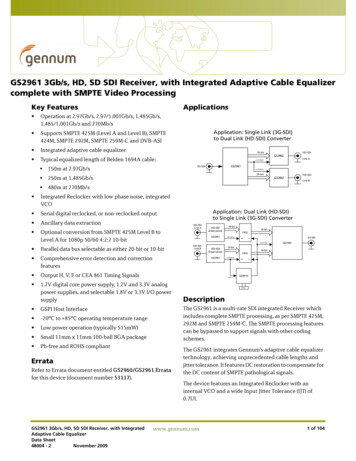
Introduction The control module is a module that implements the various device-specific functionsrequired when using the GTP transceiver to implement an SDI interface using the SMPTESDI core. The control module is supplied in source code form with this application note. The SDI wrapper is a wrapper module that instances and interconnects the SDI core andthe control module. The SDI wrapper is supplied in source code form with this applicationnote. The GTP wrapper is a wrapper file for GTP transceivers generated by the 7 Series FPGAsTransceivers Wizard, which is available in the CORE Generator and Vivado IP catalogtools. The GTP common wrapper is a wrapper file for the GTP transceiver common blockgenerated by the 7 Series FPGAs Transceivers Wizard. It contains the two PLLs thatprovide serial clocks for the GTP transceivers in the Quad.X-Ref Target - Figure 1Optional Audio(2)Embedder40 (1)40Artix-7 FPGA(1)TX ClockTX VideoTX ST352 PIDTX SDI Mode40BUFG(1)32txusrclkSMPTESDI Core2Cable Driver20txdataTX ControlGTP WrapperCable EqualizerStatusRX Status3240(1)EQ202RX ST352 PIDSDI OutResets and ControlSDI WrapperRX SDI Modetxoutclktxusrclk2SDI InrxdataControlModulerxusrclkRX Videorxusrclk2BUFGrxoutclkRX ClockGTP CommonWrapper148.5 MHz148.5/1.001 MHzReference ClockSourceX1097 01 103013Figure 1:Block Diagram of Complete SDI RX/TX InterfaceNotes relevant to Figure 1:1. These 40-bit buses are actually four buses, each of which is 10 bits wide, and each carriesa different SDI data stream. The number of active data streams, and therefore buses,varies depending on the SDI mode. For example, in SD-SDI mode, only one 10-bit datastream is active and in HD-SDI mode, two 10-bit data streams are active.2. The optional audio embedder is a separate core and is not included with the SDI core orwith this application note.The SDI wrapper includes one instance of a control module and one instance of an SDI core.The SDI core includes both an SDI RX and an SDI TX datapath. The wrapper module is usuallyXAPP1097 (v1.0.1) November 10, 2015www.xilinx.com2
Using Artix-7 GTP Transceivers for SDI Interfacesconnected to the GTP RX and TX units in the same GTP transceiver, but this does not have tobe the case. The RX and TX units of different GTP transceivers can be connected to the sameSDI wrapper. If only an SDI RX or only an SDI TX is required, the unused portions of the controlmodule and the SDI core are optimized away during synthesis.This application note includes two example demonstration applications using the SDI core.These applications run on the AC701 evaluation board. An inrevium SDI FPGA mezzanine card(FMC) is also required to provide the SDI physical interfaces.Using Artix-7GTP Transceiversfor SDI InterfacesThe information in this section is intended to supplement, not replace, the information in7 Series FPGAs GTP Transceivers User Guide (UG482) [Ref 1]. This information highlightsfeatures and operating requirements of the GTP transceivers that are of particular importancefor SDI applications.In this document, the naming convention used in the 7 Series FPGAs GTP Transceivers UserGuide for the GTP transceiver ports is followed. This convention is to use only the base nameof a port. When the 7 Series FPGAs Transceivers Wizard (hereinafter called the Wizard) isused to create a GTP wrapper, all input ports have a suffix of in and all outputs have a suffixof out. For example, when a port named txrate is discussed in this document, the actual nameof that port in the GTP wrapper would be txrate in for the txrate port of the GTP transceiver.Starting with version 3.0 of the Wizard, all GTP port names on the top-level GTP wrapper areall lower case, but only in the Vivado tools. The ISE tools version of the Wizard still producesall upper case port names. All GTP port names used in this application note are lower case.The demonstration source code files are provided in versions that are compatible with both theVivado and ISE tools and use the appropriate case for the GTP port names.Also starting with version 3.0 of the Wizard, the GTP common wrapper that contains the twoPLLs for the GTP Quad is a separate wrapper and not included in the main GTP wrapper.Again, this only applies to the Vivado tools and not to the ISE tools.There are a variety of clocks in applications using GTP transceivers. The SDI protocol, whichdoes not allow for clock correction by stuffing and removing extra data in the data stream,requires careful attention to how these clocks are generated and used in the application. GTPtransceivers require reference clocks to operate. The reference clocks are used byphase-locked loops (PLLs) in the GTP Quad to generate serial clocks for the receiver andtransmitter sections of each transceiver. As described in more detail in GTP Reference Clocks,page 4, the serial bit rate of the GTP transmitter is an integer multiple of the reference clockfrequency it is using. Furthermore, the data rate of the video provided to the input of the SDItransmitter datapath must also exactly match (or be a specific multiple of) the frequency of thereference clock used by the GTP transmitter. Consequently, the designer must determine howto generate the transmitter reference clock so that it is frequency-locked exactly with the datarate of the video stream being transmitted.The GTP transmitter outputs a clock on its txoutclk port at a frequency that is exactly equal tothe word rate of the data that must enter the txdata port of the GTP transmitter. The txoutclk isgenerated in the GTP transmitter by dividing the serial clock from the PLL down to the wordrate. In most applications, the txoutclk from the GTP transmitter is buffered by a global (BUFG)or regional (BUFR) clock buffer and then used to clock the SDI transmitter datapath and thetxusrclk and txusrclk2 clock inputs of the GTP transmitter. It is possible to use a clock other thanone derived directly from txoutclk as the clock source for the SDI transmitter datapath and thetxusrclk and txusrclk2 ports of the GTP transmitter. A shallow TX buffer in the GTP transmitterdoes allow for phase differences between the data entering the txdata port and the internalclock of the GTP transmitter. However, any frequency difference between the incoming dataand the internal clock frequency of the GTP transmitter (as represented by txoutclk) quicklycauses the TX buffer to under- or overflow, resulting in errors in the serial bit stream generatedby the GTP transmitter. Consequently, the data rate of the stream entering the txdata port of theGTP transmitter (as represented by the frequency of the txusrclk and txusrclk2 clocks) and theXAPP1097 (v1.0.1) November 10, 2015www.xilinx.com3
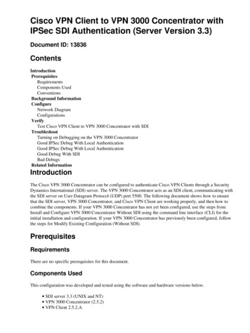
Using Artix-7 GTP Transceivers for SDI Interfacesinternal data rate of the GTP transmitter (as set by the transmitter reference clock andrepresented by the frequency of txoutclk) must match exactly.The GTP receiver reference clock, however, does not need an exact relationship with the bitrate of the incoming SDI signal. This is because the clock and data recovery (CDR) unit in theGTP receiver can receive bit rates that are up to 1250 ppm away from the nominal bit rate asset by the reference clock frequency. This allows the receiver reference clock to be generatedby a local oscillator that has no exact frequency relationship to the incoming SDI signal. TheGTP receiver generates a recovered clock that is frequency-locked to the incoming SDI bit rate.This clock is output on the rxoutclk port of the GTP transceiver. As is described in more detaillater in this application note, rxoutclk is a true recovered clock when receiving HD-SDI and3G-SDI signals, but not when receiving SD-SDI signals. Typically, rxoutclk is buffered by aglobal or regional clock buffer and then applied to the rxusrclk and rxusrclk2 ports of the GTPreceiver and used as the clock for the SDI receiver datapath.One additional clock is required for SDI applications. This is a free-running, fixed-frequencyclock that is used as the clock for the dynamic reconfiguration port (DRP) of the GTPtransceiver. This same clock is also usually supplied to the control module in the SDI wrapperwhere it is used for timing purposes. Xilinx recommends that the frequency of this clock be atleast 10 MHz. The frequency of this clock does not require any specific relationship relative toother clocks or data rates of the SDI application. This clock must not change frequencies whenthe SDI mode changes. It must always remain running at the same nominal frequency at alltimes. It also must never stop while the SDI application is active. This clock can be used for allSDI interfaces in the device.GTP Reference ClocksArtix-7 FPGA GTP transceivers are grouped into Quads. Each Quad contains fourGTPE2 CHANNEL transceiver primitives and one GTPE2 COMMON primitive containing twoPLLs called PLL0 and PLL1, as shown in Figure 2. Only the clocks from these two PLLs can beused as the serial clocks for all four receivers and transmitters in the Quad. This does presentsome limitations for SDI applications as will be described later.Each receiver and transmitter unit in the Quad can be individually configured to use the clockfrom either PLL0 or PLL1. Furthermore, any receiver or transmitter unit can dynamically switchits serial clock source between PLL0 and PLL1. This dynamic switching capability is particularlyuseful for SDI applications.XAPP1097 (v1.0.1) November 10, 2015www.xilinx.com4
Using Artix-7 GTP Transceivers for SDI InterfacesX-Ref Target - Figure 2GTPE2 CHANNELRXGTPE2 CHANNELTXRXGTPE2 CHANNELTXRXPLL0TXGTPE2 CHANNELRXTXPLL1GTPE2 COMMONREFCLK DistributionIBUFDS GTE2IBUFDS GTE2X1097 02 081513Figure 2: GTP Transceiver Quad ConfigurationTypical SDI applications require the GTP transceivers to support five different bit rates: 270 Mb/s for SD-SDI 1.485 Gb/s for HD-SDI 1.485/1.001 Gb/s ( 1.4835 Gb/s) for HD-SDI 2.97 Gb/s for 3G-SDI 2.97/1.001 Gb/s ( 2.967 Gb/s) for 3G-SDIThe CDR unit in the RX section of the GTP transceiver can support receiving bit rates that areup to 1250 ppm from the reference frequency. Because the two bit rates of HD-SDI are exactly1000 ppm different and likewise the two 3G-SDI bit rates are exactly 1000 ppm different, it ispossible to receive all five of the SDI bit rates using a single reference clock frequency.The TX section of the GTP transceiver, however, requires two different reference frequencies tosupport all five SDI bit rates. This is because the transmitters, in general, can only transmit atan exact integer multiple of the supplied reference clock frequency. Therefore, most SDIapplications provide two separate reference clocks to the GTP Quad. One of those clocks isXAPP1097 (v1.0.1) November 10, 2015www.xilinx.com5
Using Artix-7 GTP Transceivers for SDI Interfacesused as the RX reference clock and both of them are used as TX reference clocks. Usually, thesupplied reference frequency pair are 148.5 MHz and 148.5/1.001 MHz.The source of the GTP reference clocks is very application specific. The receiver referenceclock source can be a local oscillator because it does not need to match the incoming SDI bitrate exactly. However, because the GTP transmitter’s line rate is always an integer multiple ofthe reference clock frequency, the frequency of the transmitter reference clock must be exactlyrelated to the data rate of the transmitted data. Most often, the transmitter reference clocks aregenerated by genlock PLLs, thereby deriving the GTP transmitter line rate from the studio videoreference signal. In some cases, such as the SDI pass-through demonstration included with theapplication note, the transmitter line rate is derived from the recovered clock of the GTPreceiver that is receiving the SDI signal. In such cases, an external PLL is required to reducethe jitter on the recovered clock before using it as the transmitter reference clock.In a typical SDI application, one of the two reference clocks is connected to PLL0 and the otheris connected to PLL1 in each Quad that is implementing SDI interfaces. The RX units of eachtransceiver in the Quad can be configured to use the clock from either PLL. The TX units candynamically switch between the clocks from PLL0 and PLL1, depending on the bit rate that isrequired at the moment. The GTP txsysclksel port is used to select the TX unit’s clock sourcebetween the two PLLs. This common configuration for SDI applications is shown in Figure 3. Inthis figure, multiplexers that are not used dynamically in the implementation have beenreplaced with wires and the reference clock routing between Quads is not shown.X-Ref Target - Figure 3rxrateIBUFDS GTE2GTPE2 COMMON148.5 MHzPLL1148.5/1.001 MHzPLL0IBUFDS GTPE2CHANNELtxsysclkselGTPE2CHANNELtxsysclksel RX TXtxraterxrate RX TXtxraterxrate RX TXtxraterxrate RX TXtxrateX1097 03 073113Figure 3:XAPP1097 (v1.0.1) November 10, 2015Typical GTP Reference Clock Implementation for SDIwww.xilinx.com6
Using Artix-7 GTP Transceivers for SDI InterfacesAdditionally, each GTP RX and TX unit has a serial clock divider that divides the selected clockby several selectable integer powers of two. This allows, for example, all of the RX units in theQuad to use the same clock frequency from one PLL but operate at different line rates by usingdifferent serial clock divider values. This is very useful for SDI interfaces because the 3G-SDIbit rates are exactly twice as fast the HD-SDI bit rates. For 270 Mb/s SD-SDI, the GTPtransceiver runs at the 3G-SDI line rate using 11X oversampling techniques. Thus, by using twodivisors that differ by a value of two locally in each RX unit, reception of all the SDI bit rates issupported by a single RX clock frequency from one PLL. The ability of the TX units to alsolocally divide the clock source by two divisors that differ by a factor of two is also important,allowing transmission of all SDI bit rates using just two reference clock frequencies. The serialclock divider value of each RX and TX unit can be changed dynamically using the rxrate andtxrate ports of each GTP transceiver.The configuration shown in Figure 3 is an optimal solution for most SDI applications for severalreasons: The receivers can receive all SDI bit rates from one fixed reference clock frequency andone PLL provides the serial clock derived from that reference clock to all receivers in theQuad. The transmitters have the flexibility to dynamically switch between the clocks from the twoPLLs to get both serial clocks needed to transmit all supported SDI bit rates. All four receivers and all four transmitters in the Quad are fully independent, can each runat different SDI bit rates, and can dynamically switch between bit rates without disruptingthe other RX or TX units. For genlocked applications, modern genlock PLLs can simultaneously provide bothrequired reference clock frequencies from the synchronization reference input signal.In some SDI applications, it might be necessary for SDI transmitters to be running at slightlydifferent bit rates even though they are transmitting at the same nominal bit rate. This is oftenthe case with SDI routers where the bit rate of each TX must exactly match the bit rate of theSDI signal received by the SDI RX to which the TX is currently connected. In these cases, twotransmitters that are transmitting at the same nominal bit rate actually have bit rates that differby a few ppm. Supporting such applications with the Artix-7 FPGA GTP Quad structure isdifficult, and such applications might be better suited to 7 series devices with GTX or GTHtransceivers that have more PLLs available in each Quad and/or have the phase interpolationcontrol oscillator (PICXO) ported to them.Because the receivers all require an uninterrupted serial clock from one PLL, only the secondPLL in the Quad is available to provide a TX serial clock in applications like SDI routers. Thus,for these applications, the GTP Quad can only support two possible configurations where eachTX unit has its own serial clock: Four receivers using the serial clock from one PLL and a single transmitter using the serialclock from the second PLL (Figure 4) Two transmitters and no receivers active in the Quad with each transmitter using a serialclock from a different PLL (Figure 5).XAPP1097 (v1.0.1) November 10, 2015www.xilinx.com7
Using Artix-7 GTP Transceivers for SDI InterfacesX-Ref Target - Figure 4txrateGTPE2 COMMONIBUFDS GTE2GTPE2CHANNELSDI TX REFCLKPLL1 TX148.5 MHzPLL0 RXIBUFDS GTE2rxrateGTPE2CHANNEL RXrxrateGTPE2CHANNEL RXrxrateGTPE2CHANNEL RXrxrateX1097 04 073113Figure 4:Four RX and One TX in a GTP QuadX-Ref Target - Figure 5IBUFDS GTE2GTPE2 COMMONTX REFCLK 1GTPE2CHANNELPLL1 TXtxrateIBUFDS GTE2TX REFCLK 2PLL0GTPE2CHANNEL TXtxrateX1097 05 073113Figure 5:Two Independent TX in a GTP QuadResetsThe GTP transceiver has very specific reset requirements as described in the 7 Series FPGAsGTP Transceivers User Guide (UG482) [Ref 1]. The GTP transceiver requires carefulsequencing between resets of the two PLLs, gttxreset, gtrxreset, and dynamic changes ofsome GTP ports such as rxrate. Without proper coordination of all of these events, it is possiblefor the GTP transceiver to fall into a state in which it does not function properly for SDI, asituation from which the only possible recovery is to reconfigure the FPGA. The control modulesupplied with this application note enforces all of these requirements to ensure properoperation of the GTP transceiver.XAPP1097 (v1.0.1) November 10, 2015www.xilinx.com8
Using Artix-7 GTP Transceivers for SDI InterfacesGTP Initialization SequenceImmediately following FPGA configuration, the SDI control module executes initializationsequences for the GTPE2 COMMON PLLs and the RX and TX portions of the GTPtransceiver. The initialization sequence for both the RX and the TX are the same. The controlmodule has separate state machines that execute an initialization sequence separately for theRX and TX portions of the GTP transceiver. The following procedure describes the sequencefor the RX. The TX initialization sequence is identical except that the gttxreset, tx refclk stable,and txresetdone signals replace the gtrxreset, rx refclk stable, and rxresetdone signals.1. After waiting at least 500 ns following completion of FPGA configuration, assert the pllresetsignal and the gtrxreset signal.2. Wait until the rx refclk stable input is asserted, then negate the pllreset.3. Wait until the plllock signal is asserted, then negate the gtrxreset signal.4. Wait until the rxresetdone signal is asserted, then indicate that the initialization sequence iscomplete.In addition, the GTP txuserrdy and rxuserrdy inputs must be properly controlled. The SDIwrapper generates both of these signals. It asserts txuserrdy five txusrclk cycles after gttxresetis negated. Likewise, it asserts rxuserrdy five rxusrclk cycles after gtrxreset is negated.In step 2, step 3, and step 4 of the initialization sequence where the sequence is waiting on acondition to be satisfied, a timeout counter is running. If the timeout counter expires before thewait condition is satisfied, the state machine moves to a timeout state where it increments aretry counter and then cycles back in the initialization sequence and resumes the sequence. Ifthe retry counter reaches its maximum count due to numerous timeouts, the initializationsequence fails and the state machine moves to a fail state, indicating failure of the initializationsequence. The maximum number of retries allowed is controlled by a parameter/generic onthe SDI wrapper.PLL ResetsIn addition to being reset during the initialization sequences that run automatically after FPGAconfiguration, a PLL in the GTPE2 COMMON block must also be reset whenever there is achange in frequency or interruption of the reference clock supplied to that PLL. The reset isrequired to force the PLL to re-lock to the reference clock. The pll0reset and pll1reset inputs ofthe GTP wrapper are controlled by the SDI control module to implement the PLL resets. Theuser application should not assert pll0reset or pll1reset directly. The SDI control module, alone,should control the pll0reset and pll1reset signals. However, the user application determineswhen PLL resets are required and requests that the affected PLL be reset and that all of theGTP RX and/or TX units using the serial clock from that PLL also be reset.The SDI control module has two inputs that the application should use to request a full reset ofthe GTP RX (rx gtp full reset) and the GTP TX (tx gtp full reset). Asserting either of theseinputs causes the appropriate reset state machine in the control module to execute the fullinitialization sequence of the RX or TX section of the GTP transceiver, including resetting theassociated PLL. The user application must properly control the rx gtp full reset andtx gtp full reset inputs so that these initialization sequences are done whenever there is aninterruption or change in the reference clock used by the PLL.It is up to the user application to properly control the rx refclk stable and tx refclk stableinputs to the control module. These must be asserted only when the reference clocks to thePLLs are stable. As previously described, the initialization sequences wait until these inputs areasserted before negating the PLL resets. Negating the rx refclk stable or tx refclk stableinputs does not initiate a reset of the associated PLL. PLL resets are only initiated by assertingthe rx gtp full reset and tx gtp full reset inputs to the control module. The rx refclk stableand tx refclk stable are only used after the initialization sequence has been started byassertion of rx gtp full reset or tx gtp full reset.XAPP1097 (v1.0.1) November 10, 2015www.xilinx.com9
Using Artix-7 GTP Transceivers for SDI InterfacesGTP TX ResetsThere are three conditions that require the TX portion of the GTP to be reset: Whenever the PLL that supplies the serial clock to the GTP TX is reset, the gttxreset portmust be used to reset the TX section. This is done automatically after FPGA configurationby the SDI control module and whenever the user application asserts the tx gtp full resetto the SDI control module, causing both the PLL and the GTP TX to be reset. The GTP gttxreset input must be asserted during dynamic changes of the txsysclksel port.The txsysclksel port is used to select which of the two PLLs in the GTPE2 COMMONblock is used as the serial clock source for the GTP TX. Each GTP transceiver in the Quadhas its own txsysclksel port and can independently switch its serial clock source betweenthe two PLLs. The txsysclksel port should not be controlled directly by the application. TheSDI control module dynamically changes the txsysclksel port of a GTP transceiver inresponse to changes on its tx m input. When the control module detects a change on itstx m input, it first asserts the gttxreset signal, then changes txsysclksel, and then negatesgttxreset. The sequence is complete after the GTP transceiver asserts its txresetdoneoutput. At that point, the SDI control module indicates completion of the txsysclkselchange by asserting its tx change done output. The GTP TX is automatically reset by the GTP transceiver itself whenever its txrate inputport dynamically changes. The txrate controls the serial clock divider for the GTP TX. Theuser application should not change txrate directly. The SDI control module changes txrate,when appropriate, in response to changes on its tx mode input port.In addition, the user application can request a reset of the GTP TX by asserting thetx gtp reset input port of the SDI control module. This initiates a gttxreset sequence withoutresetting the PLL used by the GTP TX.All of the actions, GTP resets, and dynamic changes of txsysclksel and txrate are coordinatedby the TX control state machine in the SDI control module in order to prevent them frominterfering with each other. It is important that such interference be avoided. Thus, the userapplication should not control any of these things directly, but should rely on the SDI controlmodule to do so.The SDI wrapper has three reset inputs for the TX section: tx rst: When asserted High, this input resets the SDI TX datapath in the SDI core. tx gtp full reset: When asserted High, this input resets both the PLL associated with theTX and then the TX section of the GTP (gttxreset). These two resets are sequenced sothat the gttxreset does not complete until after the PLL reset is complete and the PLL islocked to its reference clock. tx gtp reset: When asserted High, this input resets the TX section of the GTP transceiveronly (gttxreset). If the PLL is not locked when the gttxreset sequence begins, the gttxresetsequence does not complete until after the PLL is locked.GTP RX ResetsThe RX resets are more complicated than the TX resets and must be even more carefullycontrolled. As with the TX section, the user application should rely on the SDI control module tocarefully coordinate all of the activities described in this section to prevent them from interferingwith each other.The following conditions require resets of the GTP RX section: Whenever the PLL that supplies the serial clock to the GTP RX is reset, the gtrxreset portmust be used to reset the RX section. This is done automatically after FPGA configurationby the SDI control module and whenever the user application asserts the rx gtp full resetto the SDI control module, causing both the PLL and the GTP RX to be reset. Wheneverthe gtrxreset signal is used to reset the GTP RX for any reason, a very specific sequencemust be implemented as described in the 7 Series FPGAs GTP Transceivers UserXAPP1097 (v1.0.1) November 10, 2015www.xilinx.com10
Using Artix-7 GTP Transceivers for SDI InterfacesGuide (UG482) [Ref 1]. This sequence involves using the DRP port to clear bit 11 of DRPaddress 0x011 during a portion of the sequence and then restoring it to its previous value.This bit must be 1 for normal SDI operation. A state machine in the GTP wrapperimplements this complete sequence whenever gtrxreset is asserted. Whenever the rxrate port is changed dynamically, a very specific sequence is required asdescribed in the rxrate change use model in the 7 Series FPGAs GTP Transceivers UserGuide. This sequence also involves clearing bit 11 of DRP address 0x011 during aportion of the sequence. The PMA section of the GTP transceiver is reset during thisrxrate change sequence. A state machine in the GTP wrapper implements this completesequence whenever rxrate changes. Whenever the CDR configuration of the GTP RX is changed, the gtrxreset port must beused to reset the RX section. There are two different things that the SDI control moduleuses to configure the GTP CDR correctly based on the current SDI mode (SD-SDI,HD-SDI, or 3G-SDI). The rxcdrhold port of
For example, in SD-SDI mode, only one 10-bit data stream is active and in HD-SDI mode, two 10-bit data streams are active. 2. The optional audio embedder is a separate core and is not included with the SDI core or with this application note. The SDI wrapper includes one instance of a control module and one instance of an SDI core.