Transcription
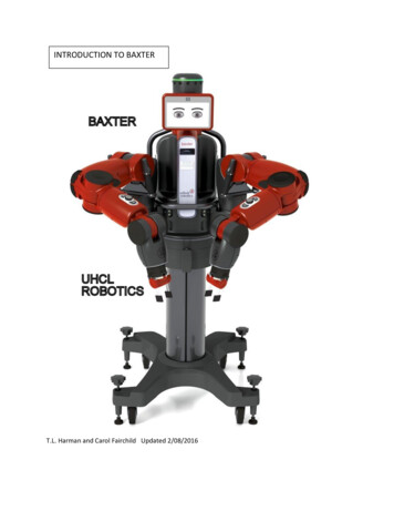
INTRODUCTION TO BAXTERT.L. Harman and Carol Fairchild Updated 2/08/2016
BAXTER INTRODUCTIONBaxter is a two-armed robot purchased for the “Robotics and Control System Laboratory” at theUniversity of Houston Clear Lake (UHCL). Baxter is housed in Delta 125 which will be referred toin this report as “Baxter’s Lab”. The robot was built by Rethink Robotics and Baxter and itsapplications are described on the web site:http://www.rethinkrobotics.com/The version of Baxter in Baxter’s lab is the research version which can be controlled via aworkstation used to create programs and execute them on Baxter. Another version of Baxter isthe manufacturing version that Rethink sells is trained by “showing” with no programmingneeded. For example, an operator moves Baxter’s arms and records positions and then replaysthe motion.Figure 1 Tom and Baxter in UHCL Lab D125This report describes the software and hardware elements of the research Baxter systemincluding the workstation and its software and Baxter’s Network. It is NOT a User’s Manual forthose wishing to run applications on Baxter. Another report Baxter User Guide will describe theuse of Baxter and its standard applications called “Rethink Baxter Examples” provided byRethink Robotics. Another report Baxter Guide for Advanced Users will describe how to writeBaxter programs or scripts. However, anyone wishing to use Baxter should have a basicunderstand of the material in this present report. 4/17/20152
1 CONTENTS ---- DON’T TRUST THE PAGE NUMBERSBAXTER INTRODUCTION . 2Baxter’s Team (November 2014) . 4INTRODUCTION. 5Table 1. Versions of Baxter’s Hardware and Development System components . 5Table 2. Versions of Software supporting Baxter . 5BAXTER’S SYSTEM . 6BAXTER’S HARDWARE . 7Baxter’s Internal Computer. 10Baxter’s 7DOF Arms . 11Zero-G Mode. 12References for the Arms and the Series Elastic Actuators: . 12Baxter’s Electric Gripper . 13Baxter’s Camera and Sensors . 14SDK SOFTWARE FOR BAXTER . 16BAXTER SIMULATORS . 17MoveIt . 17Baxter Simulator Gazebo . 18V-REP (Virtual Robot Experimentation Platform) . 19ROBOT OPERATING SYSTEM (ROS) . 20ROS Terms . 21Table 3 ROS Terms . 21ROS Tutorials and Books . 22ROS Workspace . 22UBUNTU AND BASH. 24Unity Interface . 25Terminal Interface . 27What is BASH ? . 28CONCLUSIONS . 32APPENDIX I Baxter Specifications . 33APPENDIX II Unity and Terminal Commands . 373
List of FiguresFigure 1 Tom and Baxter in UHCL Lab D125 . 1Figure 2 Angu and Harsha . 4Figure 3 Carol and Baxter. 4Figure 4 Overall Architecture of Baxter . 6Figure 5 Baxter's Physical Structure . 7Figure 6 Baxter’s External Connections . 8Figure 7 Side View of Baxter's Workspace . 9Figure 8 Baxter's Internal Circuits . 10Figure 9 Baxter's Arm and Joint Designations . 11Figure 10 Baxter's Cuff to Enable Zero-G mode. 12Figure 11 Baxter's Electric Gripper. 13Figure 12 Baxter's camera and IR Sensor in the Cuff . 14Figure 13 Baxter's SDK Software . 16Figure 14 MoveIt Simulation of Baxter . 17Figure 15 Baxter Simulator . 18Figure 16 VREP Simulation of Baxter . 19Figure 17 Example ROS nodes from Clearpath Robotics . 22Figure 18 Getting Started with Ubuntu 12.04 . 24Figure 19 Unity Desktop. 25Figure 20 Rethink Robotics Learning Page . 304
Baxter’s Team (November 2014)Abeysekera, Krishani Abeysekera@uhcl.edu ;;Carol Fairchild car.fairchild@gmail.com ;Findler, Michael Findler@UHCL.edu ;Harman, Tom harman@uhcl.edu ; McKay, Charles mcKay@uhcl.eduMiguel Rosales (RosalesM1720@UHCL.edu);Figure 2 Angu and HarshaAngusundaresh Krishnakumar (KrishnakumarA2111@UHCL.edu);Patil, Harsha (PatilH3112@UHCL.edu)Figure 3 Carol and Baxter5
INTRODUCTIONBaxter is a two-armed robot from Rethink Robotics in Boston, MA. The research version that wehave at UHCL consists of a number of elements. This report will briefly describe each elementand its use to control Baxter. Table 1 summarizes the components of a Baxter system.Baxter’sHardwareWorkStationSDK softwareBaxter SimulatorBaxter SoftwareApril 2015 versionv1.1.0v1.1.0Robot with two 7DOF arms and various sensors suchas sonar and cameras.Workstation with Development System (SDK),Rethink Baxter Examples and APIs.IP: 172.29.64.201Gazebo and MoveIt simulate Baxter.Baxter’s internal software.Baxter - http://172.29.64.200:11311Baxter NetworkIP AddressTable 1. Versions of Baxter’s Hardware and Development System componentsITEMOperatingSystem (OS)VERSIONUbuntu 14.04.2LTSTrusty TahrUSESystem Administrator – Create user accounts anddownload and maintain software.Users – file management and communication withBaxter through Terminal commands.BASHGNU bash, version4.3.11(1)-release(x86 64-pc-linuxgnu)The shell is a program that takes typed commandsfrom the keyboard and passes them to the operatingsystem or ROS to perform.Robot OperatingSystem (ROS)"Indigo" IglooPythonPython 2.7.6A software package used for Robotic softwaredevelopment. It is the interface between the OS andBaxter.The Rethink Baxter Examples are written in Python.Table 2. Versions of Software supporting Baxter6
BAXTER’S SYSTEMBaxter the Robot can be controlled from the workstation and the various programs supplied byRethink Robotics. Figure 3 shows how the workstation and Baxter are connected. Baxter has hisown IP address.The SDK interfaces with the Baxter Research Robot via ROS (Robot Operating System). Baxter provides astand-alone ROS Master to which any development workstation can connect and control Baxter via the variousROS APIs. The ROS and the APIs will be described later in this report.WorkStation IP addressBaxter’s IP AddressFigure 4 Overall Architecture of Baxterhttp://sdk.rethinkrobotics.com/wiki/Baxter Research Robot Software Developers Kit (SDK)7
BAXTER’S HARDWAREThis section describes Baxter’s basic specifications. Appendix I gives more details. Some usefuldetails are found in the various patents that have been filed or awarded to Baxter. For 2 User interfaces for robot trainingFigure 5 Baxter's Physical StructureThe Pre-delivery Guide and the Hardware Specifications describe Baxter’s 1.22.2/images/9/94/BRR pre-delivery ware SpecificationsThe Baxter Robot head display is a 1024 x 600 SVGA LCD screen capable of panning 180 andalso nodding to acknowledge user input. Baxter's head has a pan joint and a single "Nod" action8
for movement. There is one camera, one red LED ring, one green LED ring, and 12 individualyellow LEDs along with 12 sonar transducers. http://sdk.rethinkrobotics.com/wiki/HeadSome of the items in Figure 5 include:1. Condition Ring – A green lighted ring will show when Baxter is ready to work (after theinternal computer boots up)2. Attention Ring – A ring of motion sensors that indicate the presence of a person or object3. Display – The screen with resolution of 1024 x 600 pixels can be used for display ofpictures or images or show text during Baxter’s operation.In the manufacturing version, the display shows Baxter’s state when Baxter is being trained oris working. The operator uses the display to make selections via the navigator buttons in Figure 5and Baxter uses the display to communicate information to the operator. This is explained in theUser’s Guide for the manufacturing i-1.22.2/images/4/42/3.0.0 User Guide.pdfThe following video shows a good example of training the manufacturing version of Baxter:https://www.youtube.com/watch?v tWWKhp892Gk&feature em-uploademailThe training cuffs (8-9) in Figure 5 are explained in the section describing the ”zero-g mode”later. They are used extensively in the manufacturing version of Baxter but also have uses for theresearch Baxter. The cuffs are used basically to move Baxter’s arms without much resistance andalso to open and close the electric gripper in certain operations.Electrically, Baxter uses standard 120VAC power. The robot power bus and internal PC bothhave “universal” power supplies and support 90 - 264V AC (47 - 63Hz). The current is 6A at120V AC or 720W maximum.Baxter’s rear connections include the Power connector, Emergency Stop connection, USB port,Ethernet port, and Vacuum connection if a vacuum gripper is used.Figure 6 Baxter’s External Connections9
Details of Baxter’s reach and workspace are described in the workspace guidelines in the BaxterSetup Document: http://sdk.rethinkrobotics.com/wiki/Workspace GuidelinesFigure 7 Side View of Baxter's Workspace10
Baxter’s Internal ComputerProcessor 3rd Gen Intel Core i7-3770 Processor (8MB, 3.4GHz) w/HD4000 GraphicsMemory 4GB, NON-ECC, 1600MHZ DDR3Figure 8 Baxter's Internal CircuitsBaxter’s Field Service Menu (FSM) is used for setup during initial installation and otheroperations: http://sdk.rethinkrobotics.com/wiki/FSM“The Field Service Menu (FSM) is a pre-boot configuration menu that allows the user to do advanced taskssuch as check network interface configuration, change the robot computer's hostname, and run low-levelhardware checks.” This feature is normally not used by a Baxter User except for special operations.The FSM appears on Baxter’s display when activated.In Baxter’s Lab, Baxter has his own IP address - http://172.29.64.200:11311. The details arepresented in the document: http://sdk.rethinkrobotics.com/wiki/Networking11
Baxter’s 7DOF Arms S0 - Shoulder Roll S1 - Shoulder Pitch E0 - Elbow Roll E1 - Elbow Pitch W0 - Wrist Roll W1 - Wrist Pitch W2 - Wrist RollFigure 9 Baxter's Arm and Joint DesignationsBaxter’s 7 Degree of Freedom (DOF) compliant arms are described in several documents on the RethinkRobotics WEB //sdk.rethinkrobotics.com/wiki/Hardware Specifications12
The figure shows the arm and the end effector which is an electric gripper in this case. Rethinkrecommends: “Periodic recalibration will ensure that position and force sensors work well and the robot armscan move smoothly and How often does baxter need to be calibratedFor more advanced users familiar with ROS, the calibration procedure is described in the document:http://sdk.rethinkrobotics.com/wiki/Arm CalibrationZero-G ModeThe zero-g mode allows control of Baxter’s arm without resistance from the arm’s motors. The mode isdescribed in the G ModeAccording to the description: “Zero-G mode can often be confused with the mode obtained by disabling thegravity compensation torques. By default, the gravity compensation torques will always be applied when therobot is enabled. In Zero-G mode, the controllers are disabled and so the arm can be freely moved across. Inthis case, the effect of gravity would be compensated by the gravity compensation model applying gravitycompensation torques across the joints, there would be no torques from the controllers since they would not beactive, and so the arm can be moved freely around, hence the name.”“The Zero-G mode can be enabled by grasping the cuff over its groove as belowFigure 10 Baxter's Cuff to Enable Zero-G modeReferences for the Arms and the Series Elastic Actuators:The arms have a compliance which allows close and safe human interaction with Baxter. This isaccomplished through a series of elastic actuators incorporated into all 14 arm joints.Part Manipulation using Sensing and Force Control – Alex Goodwin, Rethink Robotics“Alex described Rethink Robotics flagship product, Baxter, as a robot falling into a new categoryof robotics defined by industry requirements for dexterity. As such, the Baxter platform offers13
direct manipulation as well as integral vision and force sensing of two highly dexterous 7 DOFarms. This new technology is designed to work alongside people performing human-scale tasksat human cadence, eliminating the need for safety cages. This is accomplished through a series ofelastic actuators incorporated into all 14 arm joints.” NISTIR 7940Dexterous Manipulation for Manufacturing Applications Workshop June .pdfA.I. Technical Report No. 1524 January, 1995Series Elastic Actuators, Matthew M. 721.1/6776/AITR-1524.pdf?sequence 2Baxter’s Electric GripperThe UHCL Baxter has an electric gripper. Installation is described in the ric Gripper InstallationFigure 11 Baxter's Electric GripperThe gripper has two “fingers” with removable inserts to allow different configurations of thegripping surface. According to the specifications”Positional Accuracy /- 5 mmMax Payload (including end-effector) 5 lb / 2.2 kgGripping Torque (max) 10 lb / 4.4 kgGripper maximum opening width can be adjusted by repositioning the “fingers” asdescribed in the ric Gripper Installation14
“Each hand has a 3-axis accelerometer located inside the cuff, in the same plane as the gripperelectrical connection header. The positive z-axis points back 'up' the arm (towards the previouswrist joint, w0). The positive x-axis points towards the camera, and the y-axis points towards thecuff buttons, using standard Right-Hand-Rule notation” as described in the ocs/wiki/API-ReferenceThis reference is for advanced users as it details the API and ROS topics for the Baxterhardware.15
Baxter’s Camera and SensorsBaxter has a camera in each cuff as well as an Infrared (IR) sensor to measure distance.Figure 12 Baxter's camera and IR Sensor in the CuffThe figure shows the end of the cuff with the cuff camera and the IR ranging sensor.The Camera Specifications are as follows:Max Resolution 1280 x 800 pixelsEffective Resolution 640 x 400 pixelsFrame Rate30 frames per secondFocal Length1.2mmInfrared (IR) Range Sensors in each cuff have a range of 1.5 – 15 in / 4 – 40 cmThe documents describe the cuff and the sensors in more p://sdk.rethinkrobotics.com/wiki/API Reference#SensorsExperiments in Baxter’s lab made several things clear:1. The accuracy of the distance measurement using the IR sensor varied depending on thesurface below the sensor.2. Note from the figure of the cuff camera that the center of the gripper is offset in both the xand y direction if we consider the z direction pointing up the arm when the gripper is in line withthe first joint. Thus, if the camera is used for positioning the gripper over an object to be pickedup, the offsets must be considered.16
This article is a simple discussion of IR and sonar sensors:http://www.societyofrobots.com/member tutorials/node/71Generally, a black object that is not reflective will absorb some of the IR and the distancemeasurement might be in error. A white table top, for example, reflects the IR very well andBaxter’s IR sensor calculated the distance from the table accurately and repeatedly.17
SDK SOFTWARE FOR BAXTERThe next Figure shows the elements of software loaded on the workstation to download softwareor operate Baxter. Notice the Baxter Interface, Examples and Tools software modules. These willbe described in detail in another report Baxter User’s Guide which will describe the use ofBaxter and its standard applications called “Rethink Baxter Examples” provided by RethinkRobotics.18
Figure 13 Baxter's SDK SoftwareBAXTER SIMULATORSMoveItThe Rethink document presents a detailed tutorial about the use of MoveIt.http://sdk.rethinkrobotics.com/wiki/MoveIt Tutorial“MoveIt! motion planning framework provides capabilities including Kinematics (IK, FK, Jacobian), MotionPlanning (OMPL, SBPL, CHOMP) integrated as MoveIt! plugins, Environment Representation (robotrepresentation, environment representation, collision checking, contraint evaluation), execution usingmove groups, benchmarking, warehouse database for storage (scenes, robot states, motion plans), aC /Python API and more!”In short, MoveIt allows path planning with obstacles in Baxter’s path and then execution of thepath on the “real” Baxter.A very useful video from Rethink explains the use of MoveIt.Baxter Research Robot MoveIt! TutorialRethink Roboticshttps://www.youtube.com/watch?v 1Zdkwym42P4Figure 14 MoveIt Simulation of BaxterTo use MoveIt, the Rviz (ROS visualization) window will then open showing Baxter withinteractive markers. The markers are used to move Baxter’s arms in the simulation.“ rviz (ROS visualization) is a 3D visualizer for displaying sensor data and state information from ROS. Usingrviz, you can visualize Baxter's current configuration on a virtual model of the robot. You can also display liverepresentations of sensor values coming over ROS Topics including camera data, infrared distancemeasurements, sonar data, and more.”19
Baxter Simulator GazeboThe site http://sdk.rethinkrobotics.com/wiki/Baxter Simulator describes the Baxter Simulator. Itis used to model Baxter and environments. Rethink defines Baxter’s characteristics in the formof a URDF (Unified Robot Description Format). Baxter automatically builds his URDF on bootup. It is accessible by ROS utilities, Gazebo and other simulators.“Gazebo is a multi-robot simulator in a 3-dimensional world. It comes with advanced plugin interfaces that canbe used to simulate the sensor feedback and plausible interactions between objects. There are standardmodels available within gazebo that can be used with custom models.”Figure 15 Baxter Simulator20
V-REP (Virtual Robot Experimentation Platform)Marc Freese“The video shows the Baxter robot in the V-REP robot simulator ( http://www.coppeliarobotics.com ). Itillustrates several of V-REP's features: simple scene composition, physics, motion planning, inversekinematics, etc. The video shows the Baxter robot doing some object manipulation. The simulation usesV-REP's built-in motion planning and inverse kinematics algorithms. The Baxter CAD data is courtesy ofRethink Robotics.”https://www.youtube.com/watch?v PHuQZDp8kt8Figure 16 VREP Simulation of BaxterThe User’s Manual is available at this site: ml21
ROBOT OPERATING SYSTEM (ROS)ROS is sometimes called a “meta operating system” because it performs many of the functionsof an operating system. One of its main purpose is to provide communication between the user,the Ubuntu OS and of course Baxter. As with any operating system, the benefit of ROS is thehardware abstraction and low-level control of Baxter without the Baxter user knowing all of thedetails of the robot. For example, to move Baxter’s arms, a command to ROS is issued and ROScommunicates with the scripts1 in Python written by the Rethink designers to cause Baxter torespond as commanded. Baxter is defined to ROS by the designers at Rethink Robotics invarious ways describe later.For a little history:http://en.wikipedia.org/wiki/Robot Operating System“ROS was originally developed in 2007 under the name switchyard by the Stanford ArtificialIntelligence Laboratory in support of the Stanford AI Robot STAIR project. From 2008 until2013, development was performed primarily at Willow Garage, a robotics researchinstitute/incubator. During that time, researchers at more than twenty institutions collaboratedwith Willow Garage engineers in a federated development model.In February 2013, ROS stewardship transitioned to the Open Source Robotics Foundation. InAugust 2013, a blog posting[11] announced that Willow Garage would be absorbed by anothercompany started by its founder, Suitable Technologies. The support responsibilities for the PR2created by Willow Garage were also subsequently taken over by Clearpath Robotics”.The link to Clearpath Robotics is http://www.clearpathrobotics.com/Our Baxter now (2015) uses the Indigo release of ROS:ROS Indigo Igloo is the eighth ROS distribution release and was released July 22nd, 2014. Quotefrom: http://wiki.ros.org/indigo1The Python scripts in turn call various software elements including the Baxter APIs (application programminginterfaces) that cause the actual motion of Baxter’s arms.22
ROS TermsBefore a beginner even opens a web tutorial or book or sees a ROS video, it is helpful to learn afew terms that pertain to ROS. These terms describe the main components of a ROS system.Table 2. ROS Useful TermsItemTypeRepositories A software repositoryis a storage locationfrom which softwarepackages may beretrieved and installedon a computer.PackagesManifestServicesNodesROS MasterMessagesTopicBagsContains files toallow execution ofROS programsInformation about apackageAllowscommunicationbetween nodes.Processes thatexecute commands.Registers the nameand location of eachnode.Data sent betweennodes.Name of a message.Data storage formessages.Table 3 ROS TermsCommenthttp://en.wikipedia.org/wiki/Software repositoryGitHub is used to download the ROS packages usedby the Baxter tion SetupA package typically contains source files andexecutable scripts that can be BASH, Python, or othercode.The manifest defines properties about the packagesuch as the package name, version numbers, authors,maintainers, and dependencies on other packages.Used by nodes to communicate with other nodes andrequest a response.Executable code written in Python or C usually.Python nodes use the client library rospyAllows nodes to communicate. Nodes can be indifferent computers.Messages are “published” by a node and “subscribedto” by another node.For example, Baxter’s cameras “publish” the imagethey receive as a topic with a name that indicates it is acamera image.Used to save and playback data such as sensor data.23
Figure 17 Example ROS nodes from Clearpath RoboticsROS Tutorials and BooksA large number of tutorials are available at the ROS.ORG site: http://wiki.ros.org/ROS/TutorialsThe tutorials at this site and many other tutorials should probably be called “ROS tutorialsfor those familiar with Ubuntu, Python or C , and ROS itself”. Check to see that the referencesor books cover your version of the software.The textbook Learning ROS for Robotics Programming by Aaron Martinez is useful. Theexamples are in C .A Gentle Introduction to ROS by JasonM. O’Kane is very readable and can be downloaded fromthe site: http://www.cse.sc.edu/ jokane/agitr/agitr-letter.pdfROS WorkspaceThe files for ROS and Rethink Baxter examples are downloaded into the ROS workspace whenthe system is created by downloading the software from the GitHub repositories. The instructionsfrom Rethink Robotics are located at the web on SetupThe setup procedure is not discussed here as it is assumed that this Introduction to Baxter will beused by those whose system is installed.24
The command that causes communication between the workstation and Baxter is invoking theBaxter shell from the terminal window with a command such as: ./baxter.shThe result would indicate Baxter’s IP address, the user, and that the current directory is ros ws inthe example from Baxter’s lab at UHCL:[baxter - http://172.29.64.200:11311] tlharmanphd@D125-43873: /ros ws Baxter is now ready to execute user commands.The examples described in this report are from the UHCL Baxter lab. Any other setup ofthe Baxter software possibly would use different names for the directories, different IP addressesand certainly different user names for logging in to the system. These details must be determinedby the system administrator who setup the system.Details about linking the workstation and Baxter are describe in this Rethink rkingIt is intended for those who understand networks and ROS Naming Conventions. For advancedusers, the ROS tutorial might be helpful: http://wiki.ros.org/ROS/NetworkSetup25
UBUNTU AND BASHBorrowing from Wikipedia, the free encyclopedia:Ubuntu (/uːˈbuːntuː/ oo-BOON-too) is a Debian-based Linux operating system, with Unity as its defaultdesktop environment (GNOME was the previous desktop environment). It is based on free software andnamed after the Southern African philosophy of ubuntu (literally, "human-ness"), which often istranslated as "humanity towards others" or "the belief in a universal bond of sharing that connects allhumanity". http://en.wikipedia.org/wiki/Ubuntu (operating system)There are so many books, articles,
Feb 08, 2016 · INTRODUCTION Baxter is a two-armed robot from Rethink Robotics in Boston, MA. The research version that we have at UHCL consists of a number of elements. This report will briefly describe each element and its use to control Baxter. Table 1 summar
