Transcription
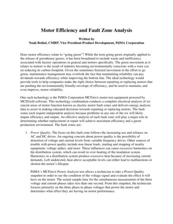
Motor Efficiency and Fault Zone AnalysisWritten byNoah Bethel, CMRP, Vice President-Product Development, PdMA CorporationDoes motor efficiency relate to “going green”? While the term going green originally applied tothe release of greenhouse gasses, it has been broadened to include waste and inefficiencyassociated with factory operations in general and motors specifically. The green movement as itrelates to motors is the result of industry becoming environmentally conscious with a wary eyeon reducing its carbon footprint. Given the sometimes frenzied movement in the effort to gogreen, maintenance management may overlook the fact that maintaining reliability can paydividends towards efficiency while improving the bottom line. The ideal technology wouldprovide tools to help companies make the right choice between repairing or replacing motors thatare pushing the environmentally friendly envelope of efficiency, and be used to maintain, andeven improve, motor reliability.One such technology is the PdMA Corporation MCEMAX motor test equipment powered byMCEGold software. This technology combination conducts a complete electrical analysis of sixcrucial areas of motor function known as electric motor fault zones and delivers energy analysisdata to assist in making educated decisions towards repairing or replacing motors. The faultzones each require independent analysis because problems in any one of the six will likelyimpair efficiency and output. An effective analysis of each fault zone will play a major role indetermining whether replacement or repair will achieve maximum efficiency and a greenproduction environment. The fault zones are:1. Power Quality. The focus on this fault zone follows the increasing use and reliance onAC and DC drives. An ongoing concern about power quality is the possibility ofdistortion of voltage and current levels from variable frequency drives. Other sources oftrouble with power quality include non-linear loads, starting and stopping of nearbyequipment, voltage spikes, and more. These influences can cause excessive harmonics onthe distribution system, which can result in over-heating of the insulation system.Harmonics in a distribution system produce excessive heat because of increasing currentdemands. Left undetected, heat above acceptable levels can either lead to malfunctions orshorten the motor’s lifespan.PdMA’s MCEMAX Power Analysis test allows a technician to take a Power Qualitysnapshot in order to see the condition of the voltage signal and evaluate the effect it willhave on the motor. The actual sample time for the simultaneous measurement of the threevoltage and current phases takes less than one second. From this snapshot, the technicianfocuses primarily on the three phase-to-phase voltages that power the motor anddetermines what effect they are having on motor performance.
Data used to evaluate Power Quality is located in the phase-to-phase voltage section ofthe Results Page (Figure 1). Fundamental RMS, Total RMS, Crest Factor (CF), and TotalHarmonic Distortion (THD) are listed for each of the phase-to-phase voltages. Theaverage voltage and percent imbalance are also listed. Additionally, recommendedNEMA derating factors are provided for both phase-to-phase voltage imbalance andHarmonic Voltage Factor (HVF).Figure 12. Power Circuit. This fault zone is defined as the system of conductors and connectionsrunning from the point of origin of testing to connections at the motor. The circuit caninclude breakers, fuses, contactors, and lug connections. There should be no doubt that aproblem in the power circuit impairs efficiency. A study conducted in the mid-1990sdetermined that more than 46 percent of the faults found in industrial power distributionsystems that reduced motor efficiency stemmed from difficulties within either theconnectors or conductors. Faulty power circuit conditions place the most efficient andwell maintained motor at risk for reduced horsepower that can lead to excessive heat andinsulation damage.High resistance connections in the power circuit result in unbalanced terminal voltages atthe motor. The consequences of the unbalanced terminal voltage are: overheating of thecomponents adjacent to the high resistance connection, loss of torque, other phasesdrawing additional current to compensate, overheating of the insulation system, and adecrease in motor efficiency. Voltage imbalances will cause the motor to draw morecurrent in order to perform the required work. Therefore, not only does the customer facepremature motor burn out (or single-phase), but also they may potentially pay for extrakilowatt-hours and possibly a demand penalty.Another result of voltage imbalance is the creation of negative sequence currents. Thesecurrents are named negative sequence because of the development of a magnetic fieldopposing motor rotation. This added load requires the motor to draw more current to
power the load being driven. The long-term effect will be shortened insulation life due tothe added thermal stress.The values from the Power Analysis test that are used to evaluate the health of the powercircuit are: phase-to-phase voltage, phase-to-phase current, and their respectiveimbalances. These measured values are recorded and compared against industrystandards. Due to the negative effects from an imbalanced bus voltage, NEMA MG-1recommends that a motor not operate if the voltage imbalance reaches 5%. NEMAprovides a Derating Curve that shows a factor for derating motor horsepower due to thevoltage imbalance experienced by the motor.An unbalanced power delivery not only causes a voltage imbalance, but it will also causea much higher percent current imbalance. Some thumb rules to apply whentroubleshooting the power circuit. A 1% voltage imbalance can result in a 6–7% current imbalance, according to theElectrical Apparatus Service Association (EASA).A 3.5% voltage imbalance can raise winding temperatures by 25%, according tothe Electrical Power Research Institute (EPRI).A 10 Celsius increase in winding temperature (above design) can result in a 50%reduction of motor life.Phase voltage unbalance causes three-phase motors to run at temperatures greater thantheir published ratings. This excessive heating is due mainly to negative-sequencecurrents attempting to cause the motor to turn in a direction opposite to its normalrotation. These higher temperatures soon result in degradation of the motor insulation andshortened motor life. The percent increase in temperature of the highest current windingis approximately two times the square of the voltage unbalance. For example, a 3%voltage unbalance will cause a temperature rise of about 18%.3. Insulation. There is potential for damage to the insulation between the windings and theground, which is generally caused by dirt contamination, high temperatures, moisture andage. A faulty power circuit is the culprit in insulation damage, but advanced testing isrequired to ascertain if the damage was the cause of a motor disruption or something else— a symptom of another problem yet to be analyzed.By definition, the insulation resistance is made up of the applied direct voltage acrossthe insulation divided by the total resultant current. The total current is the sum of fourdifferent currents: geometric capacitance, conductance, surface leakage, and absorption.The geometric capacitance current is a reversible component of the measured currenton charge or discharge that is due to the geometric capacitance. That is the capacitance asmeasured with alternating current of power or higher frequencies. With direct voltage thiscurrent has a very short time constant and does not affect the usual measurement.
The conduction current in well-bonded polyester and epoxy-mica insulation systems isessentially zero unless the insulation has become saturated with moisture. Olderinsulation systems, such as asphaltic-mica or shellac mica-folium may have a natural andhigher conduction due to the conductivity of the tapes used back of the mica.The surface leakage current is constant over time. Moisture or some other type ofpartially conductive contamination present in the machine causes a high surface leakagecurrent, i.e., low insulation resistance.The absorption current is made of two components: the polarization of the insulationmaterial and the second is due to the gradual drift of electrons and ions through theinsulating material. The polarization current is caused by the reorientation of theinsulating material. This material, usually epoxy, polyester, or asphalt tends to change theorientation of their molecules when in the presence of direct electric field. It normallytakes a few minutes of applied voltage for the molecules to have been reoriented, andthus for the current-supplied polarizing energy to be reduced to almost zero. Theabsorption current, which is the second component, is the gradual drift of electrons andions through the insulating material. These electron and ions drift until they becometrapped at the mica surfaces usually found in rotating insulation systems. See Figure 2.Section A of Figure 2 shows the random orientation of the insulation’s molecules. As adirect voltage is applied via the MCEtester, the molecules start to polarizeand align, see Section B of Figure 2.The energy required to align themolecules, and subsequently reduce theamount of escaping molecules, is knownas absorption current.Since absorption current is a property ofthe insulation material and the windingtemperature, a specific absorptioncurrent is neither good nor bad. Theabsorption currents will vary fromdifferent insulating material. Prior to1970, older thermoplastic materials usedwere typically asphalt or shellac whichhave a higher absorption current. After1970, the shift was made toFigure 2thermalsetting polyester or epoxybonded insulating material, which significantly decreased the absorption current.Nonetheless, this doesn’t mean that the more modern insulating materials are betterbecause they have less absorption current.
4. Stator. This fault zone is sometimes misunderstood. A stator consists of copper windingsconnected with solder joints between the coils. Electrical engineers sometimes differ onthe role of the stator as the root cause or symptom. Outside of design or manufacturingdefects, the stator is often the symptom of another fault mechanism. The real goal forstator-related incidents is to identify conditions conducive to stator faults and correctthem before they result in a stator failure. Stator failures can often be catastrophic,resulting in unplanned outages and defective products, which increase the use of energyand create waste.The likely mechanisms of a stator-winding fault are either a turn-to-turn, phase-to-phase,or turn-to-ground short. A turn-to-turn short is identified as a short of one or morewindings in a coil. This can develop into a very low impedance loop of wire, which actsas a shorted secondary of a current transformer. This results in excessive current flowthrough the shorted loop, creating intense heat and insulation damage. Due to the natureof a random wound design, a shorted turn could occur with much higher impedance,allowing the motor to run for extended periods of time before eventually destroying thecoil with the high currents. Form wound coils however, do not exhibit high turnimpedances and will therefore heat up quickly following the presence of a turn-to-turnshort. A phase-to-phase short is identified as a short of one or more phases to anotherphase. This fault can be quite damaging due to the possibility of very large voltagepotential existing between phases at the location of the short.5. Rotor. In more specific terms, the rotor fault zone refers to the rotor bars, laminations andend rings. The percentage of motor failures attributed to rotor problems is low, but itstrouble spots can cause extensive damage to the motor if left unchecked. The stator isalso at risk because of its close proximity to the rotor. For example, a cracked rotor barwill lead to a heat build-up intense enough to melt insulation on its laminations as well ason the nearby stator. Again motor efficiency will be compromised without the advancedtechnology necessary to detect a crack or break in the bars.The design of the rotor plays a major role in the severity of an identified rotor anomaly. Ifthe rotor is a closed bar design (Figure 3) the severity will be low due to the rotor ironacting to hold the broken rotor bar in place. However, if the rotor is an open bar design(Figure 4) then the severity increases significantly with the identification of a rotordefect. This elevated concern comes from the possibility of the rotor bar squeezing out ofthe rotor slot and contacting the stator.6.Figure 3Figure 4
6. Air Gap. The gap between the rotor and stator assures efficiency when it is evenlydistributed around 360 degrees of the motor. When distribution is uneven or nonsymmetric, the usual result is an unbalanced magnetic field and high vibration levels.Over time, these elevated levels of vibration can result in excessive movement of thestator winding, which could lead to increased friction and eventually a turn-to-turn, coilto-coil, or ground fault. Additionally, this vibration can accelerate bearing failure, whichcould seize the shaft and overheat the windings or allow additional movement of the shaftleading to a rotor/stator rub. The uneven magnetic stresses applied to the rotor coupledwith the increased vibration will also contribute to mechanical looseness developing inthe rotor. Any of these occurrences could lead to a catastrophic failure of the motor,which could require a complete rewind and possible restacking of the iron. Whether it isbearing failure or a rotor/stator rub, these increased losses have a direct impact on theoperating efficiency of the motor.All six fault zones have one requirement in common: ongoing testing of the highest standardsand tolerances that will help assure efficiency and reliability. When it comes to efficiency andreliability, chances of achieving one without the other are unlikely. Going green without both isimpossible.About the Author:Noah Bethel is vice president of product development for PdMA Corporation, Tampa, Fla., aleader in the field of predictive maintenance, condition monitoring applications, anddevelopment of electric motor test equipment for motor circuit analysis. Tel: (800) 476-6463 orvisit www.pdma.com.
even improve, motor reliability. One such technology is the PdMA Corporation MCEMAX motor test equipment powered by MCEGold software. This technology combination conducts a complete electrical analysis of six crucial areas of motor function known as electric motor fault zones and delivers energy analysis