Transcription
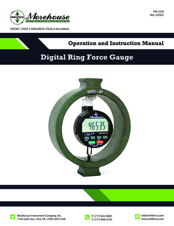
PM-2150Rev. 3/2022ISO/IEC 17025 / ANSI/NCSLI Z540.3 AccreditedOperation and Instruction ManualDigital Ring Force GaugeMorehouse Instrument Company, Inc.1742 Sixth Ave., York, PA 17403-2675 USAP: (717) 843-0081F: (717) 846-4193info@mhforce.comwww.mhforce.com
Digital Ring Force GaugeManual(PM-2150)Table of ContentsSafety . . . . . . . . . . . . . . . . . . . . . . . . . . . . . . . . . . . . . . . . . . . . . . . . . . . . . . . . . . . . . . . . . . . . . . . . . . . . . . . . . . . . . . 3Introduction . . . . . . . . . . . . . . . . . . . . . . . . . . . . . . . . . . . . . . . . . . . . . . . . . . . . . . . . . . . . . . . . . . . . . . . . . . . . . . . . . . 4Preparation for Loading . . . . . . . . . . . . . . . . . . . . . . . . . . . . . . . . . . . . . . . . . . . . . . . . . . . . . . . . . . . . . . . . . . . . . . . 5-6Operation Instructions . . . . . . . . . . . . . . . . . . . . . . . . . . . . . . . . . . . . . . . . . . . . . . . . . . . . . . . . . . . . . . . . . . . . . . 6-10Compression and Tension Setup . . . . . . . . . . . . . . . . . . . . . . . . . . . . . . . . . . . . . . . . . . . . . . . . . . . . . . . . . . . . . . . . . 7Indicator Operation . . . . . . . . . . . . . . . . . . . . . . . . . . . . . . . . . . . . . . . . . . . . . . . . . . . . . . . . . . . . . . . . . . . . . . . . 8-10Changing Indicator Battery . . . . . . . . . . . . . . . . . . . . . . . . . . . . . . . . . . . . . . . . . . . . . . . . . . . . . . . . . . . . . . . . . . . . 10Calibration . . . . . . . . . . . . . . . . . . . . . . . . . . . . . . . . . . . . . . . . . . . . . . . . . . . . . . . . . . . . . . . . . . . . . . . . . . . . . . . 11-12Calibration Procedure . . . . . . . . . . . . . . . . . . . . . . . . . . . . . . . . . . . . . . . . . . . . . . . . . . . . . . . . . . . . . . . . . . . . . . . . 11Resolution . . . . . . . . . . . . . . . . . . . . . . . . . . . . . . . . . . . . . . . . . . . . . . . . . . . . . . . . . . . . . . . . . . . . . . . . . . . . . . . . . . 11Frequency of Calibration . . . . . . . . . . . . . . . . . . . . . . . . . . . . . . . . . . . . . . . . . . . . . . . . . . . . . . . . . . . . . . . . . . . . . . 12Maintenance . . . . . . . . . . . . . . . . . . . . . . . . . . . . . . . . . . . . . . . . . . . . . . . . . . . . . . . . . . . . . . . . . . . . . . . . . . . . . . . . 13Upgrade from Analog Ring Force Gauge . . . . . . . . . . . . . . . . . . . . . . . . . . . . . . . . . . . . . . . . . . . . . . . . . . . . . . . . . . 13Temperature Correction for Digital Ring Force Gauges . . . . . . . . . . . . . . . . . . . . . . . . . . . . . . . . . . . . . . . . . . . 14-15Fahrenheit Scale (Drawing 99332) . . . . . . . . . . . . . . . . . . . . . . . . . . . . . . . . . . . . . . . . . . . . . . . . . . . . . . . . . . . . . . 14Centigrade Scale (Drawing 99332-1) . . . . . . . . . . . . . . . . . . . . . . . . . . . . . . . . . . . . . . . . . . . . . . . . . . . . . . . . . . . . 15Morehouse Instrument Company, Inc.1742 Sixth Ave., York, PA 17403-2675 USAPhone: (717) 843-0081www.mhforce.comPage 2Rev. 3/2022
Digital Ring Force GaugeManual(PM-2150)SafetyFor general guidelines about force calibration safety, refer to the Morehouse Force Measurement EquipmentSafety guide PG-9000. In addition, the following safety practices must be exercised when using a Digital RingForce Gauge. Read the instruction manual carefully and ensure that anyone who intends to operate the machine hasproper training on safe practices of using a portable calibrator.Inspect all components of the Digital Ring Force Gauge, and any components used from a connection before use to ensure all parts are free of defect and are attached properly.Digital Ring Force Gauges can only be used under the rated capacity. Overloading a Digital Ring Force Gaugemay cause a dangerous situation for the user and permanently damage the instrument.To avoid situations that may cause personal injuries wear eye protection at all times when using a Morehouse Digital Ring Force Gauge or any other force measuring instrument.Any adapter or accessory you may design, make or purchase for use with a portable calibrator, or forcemeasuring instrument, must be of proper design and made from steel of the proper strength to withstandthe forces to which it is subjected. It is most important that adapters and accessories be test loaded undersafe conditions prior to actual use with an instrument. Equipment should not be used beyond its maximumrated capacity. Failure to use the proper strength material may result in serious injury or death.Applying forces to equipment and instruments is inherently dangerous. This document does not, and cannot,foresee all safety considerations in your testing and application environments. It is important to give carefulconsideration to any application of force.Morehouse Instrument Company, Inc.1742 Sixth Ave., York, PA 17403-2675 USAPhone: (717) 843-0081www.mhforce.comPage 3Rev. 3/2022
Digital Ring Force GaugeManual(PM-2150)IntroductionThe Digital Ring Force Gauge is relatively simple to operate. If maximum accuracy is desired the Digital RingForce Gauge should be placed near the location where it is to be used and allowed to stabilize at the ambient temperature that will prevail during use. Deviations from the temperature at which the Digital Ring ForceGauge was calibrated will cause errors of approximately 1% for every 70 degrees F.A Digital Ring Force Gauge consists of a load ring that deflects under compressive or tensile forces. The deflection of the ring is continuously measured by a digital indicator mounted inside the ring. The indicator is programmed by the Morehouse primary force calibration laboratory and interprets the deflection values to directcalibrated force values and displays on the digital screen.The indicator displays the force in the engineering units as specified by the user at the time of purchase. Theoperator will not need an additional electronic indicator to read the sensor output and does not need an interpretation table to convert and interpolate readings to calibrated force values.Typically, the capacity of the instrument is engraved on the front side of the ring, and the indicator is set todisplay force in the same units used to express the instrument capacity.A standard Digital Ring Force Gauge includes the components shown below:Loading Adapter(varies by models & capacity)Carrying CaseLoad RingDigital Indicator DisplayIndicator KeypadLoading Adapter(varies by models & capacity)Figure 1: Digital Force Gauge Standard ComponentsMorehouse Instrument Company, Inc.1742 Sixth Ave., York, PA 17403-2675 USAPhone: (717) 843-0081www.mhforce.comPage 4Rev. 3/2022
Digital Ring Force GaugeManual(PM-2150)Preparation for LoadingCompressionIf the Digital Ring Force Gauge is to be loaded against the spherical surface on the top boss, then a pieceof cold rolled steel (loading pad) should be inserted between the top boss or button and the upper surfaceagainst which it will bear. This will prevent the button from causing an indentation in the upper surface. Following is a list of recommended sizes for the cold rolled steel to be used:Capacities through 50,000 lbf – 2” x 2” x 0.5” ThickCapacities 50,001 through 100,000 lbf – 3” x 3” x 0.5” ThickCapacities 100,0001 through 200,000 lbf – 4” x 4” x 0.75” ThickCapacities 200,001 through 500,000 lbf – 4” x 4” x 1.5” ThickCapacities 500,0001 through 1,000,000 lbf – 5” x 5” x 2.0” ThickThe surface on which the lower boss will bear should be flat to minimize non-axial loading. If the Ring ForceGauge is to be loaded using a load ball in place of the spherical surface on the top boss, then the surfacesopposing the ball should have a ball seat approximating the dimensions shown on in Figure 1. When loadingthrough a steel ball, be certain that the ball is made of hardened chrome alloy steel and it is the recommendedsize to withstand the force applied. Never use a carbide ball because carbide is brittle and will shatter underload.Capacity (lbf) A Dia.BCD Dia.E 750.750.880.880.880.880.88Figure 2: Ball Seat DimensionsMorehouse Instrument Company, Inc.1742 Sixth Ave., York, PA 17403-2675 USAPhone: (717) 843-0081www.mhforce.comPage 5Rev. 3/2022
Digital Ring Force GaugeManual(PM-2150)TensionWhen mounting a tension type Digital Ring Force Gauge keep any special attachments or adaptors in asclose alignment as possible.OperationAfter mounting the Digital Ring Force Gauge in the press or other assembly in which the mechanical forces areto be measured, the force gauge should be exercised two or three times to stabilize it. Load the Digital RingForce Gauge to its capacity or the force to which it is to be used, whichever is lower, and release it.The versatile ring force gauge can be applied in many different ways and applications are limitless. It is suppliedwith tapped holes in external bosses so it can be easily fitted with special adaptors, accessories, or mountingbrackets of base plates that are incorporated into an application. Please contact us if you have any questionsabout how the Digital Ring Force Gauges can be applied, or about adapters you may need.The dial indicator used to measure the deflection of the ring is accurate to 0.001 mm and provides high stability over time. The indicator is programmed during calibration and adjusted to convert ring deflection valuesto force in the units specified by user at the time of purchase. The indicator also provides a number of usefulmeasurement features which are explained in the operation section of this manual.Morehouse Instrument Company, Inc.1742 Sixth Ave., York, PA 17403-2675 USAPhone: (717) 843-0081www.mhforce.comPage 6Rev. 3/2022
Digital Ring Force GaugeManual(PM-2150)Compression and Tension SetupModel FRCDesigned and calibrated to measure compressive forces onlyCapacitySetupLower than or equal to 2,500 lbfA base adapter is threaded into the lower boss of the force gauge toprovide stability.A load button is threaded into the upper boss to help with load linealignment.Higher than 2,500 lbfLarger bosses keep the force gauge stable. The upper boss has a spherical surface which can be loaded against directly.A chamfer in the upper boss can accommodate a load ball. A load ball isrecommended to help with better load line alignment.Model FRTDesigned and calibrated to measure tension forces onlyCapacitySetupLower than or equal to 10,000 lbf A set of two rod ends can be used to measure tensile forces and helpwith tensile load line alignment.Higher than 10,000 lbfThreaded upper and lower bosses for special adapters. Typically, gaugesin this capacity range are used for special high force measurement applications and need special adapters for their application. Morehouse canhelp users find safe and reliable solutions for their specific application.Other adapters can be used to generate tensile loading setups. Prior to using any tension adapters, the operator must ensure the adapters are rated for the force that will be applied to the instrument during the forcemeasurement process. Morehouse manufactures a large variety of tension adapters which can be used withDigital Ring Force Gauges to produce tension force calibration setups for almost any application.Morehouse Instrument Company, Inc.1742 Sixth Ave., York, PA 17403-2675 USAPhone: (717) 843-0081www.mhforce.comPage 7Rev. 3/2022
Digital Ring Force GaugeManual(PM-2150)Indicator OperationThe indicator in the Digital Ring Force Gauge features some built-in functions which can assist with specialforce applications. The following instructions can be used to activate these functions or switch to differentmodes. All the indicator operations are performed through the small keypad on the indictor. Figure 3 demonstrates the layout of the indicator keypad.Figure 3: Layout of the Indicator KeypadPower On/OffTo turn the unit on, press and hold ON/CLR until indicator turns on. To turn off, press OFF/MODE.Reset DisplayPushing the ON/CLR button on the indicator Clears/resets display to ‘0’ or spindle position.Auto-Off ToggleTo turn the Auto-Off function on or off, press the 2ND button (2ND icon should appear on the display). Pressthe OFF/MODE. An hour glass appears at the left side of the display if AUTO OFF is active. If AUTO OFF is activethe indicator will power off in 10 minutes with no activity (button press or spindle movement).Morehouse Instrument Company, Inc.1742 Sixth Ave., York, PA 17403-2675 USAPhone: (717) 843-0081www.mhforce.comPage 8Rev. 3/2022
Digital Ring Force GaugeManual(PM-2150)Hold ModeThe Hold Mode allows user to hold the value on the display according to the specified mode. Press HOLD totoggle hold mode on and off.MAX (Compression Max Hold)Holds and displays the highest reading attained. When the Digital Ring Force Gauge is in compression, theindicator displays a positive value, and when the MAX HOLD is on, the highest compressive force is displayed.When the Digital Ring Force Gauge is under tension, the indicator displays a negative number, and when MAXHOLD is on, the minimum tensile force is displayed.MIN (Tension Max Hold)Holds and displays the lowest reading attained. When the Digital Force Gauge is in compression, the indicatordisplays a positive value, and when the MIN HOLD is on, the lowest compressive force is displayed. When theDigital Force Gauge is under tension, the indicator displays a negative number, and when MIN HOLD is on, themaximum tensile force is displayed.FRZHolds and displays the reading displayed when HOLD button is pressed.To select type of HOLD (MAX, MIN, FRZ), press HOLD continuously until desired feature is flashing on the display, then release HOLD. Note that pressing ON/CLR button resets indicator to spindle position except in FRZ;resets to zero.TIR ModeTotal Indicator Runout (TIR) mode ignores loading mode (compression or tension), instead measures the difference between peak and valley (MAX and MIN) values. Additionally, in this mode, the maximum and minimumvalues for entire loading period is stored in the memory and can be retrieved. To enter TIR Mode, continuouslypress the OFF/MO DE button until the diamond icon appears above the TIR function. In TIR mode, the Freeze(FRZ) is the only hold function available. To view the Peak (MAX) Value or the Valley (MIN) Value, use the HOLDbutton. Press HOLD button down until the MIN or MAX is displayed. The difference between the MIN andMAX Values equals the TIR Value. It should be noted that the gauge displays the numerical difference betweenhighest and lowest values, while compressive forces are displayed in positive numbers and tensile forces aredisplayed in negative numbers.NOTE: to change the measurement mode of the indicator, press and hold the OFF/MODE button. While thisbutton is pressed down, the indicator switches between modes continuously, and a triangle or diamond flashesat the lower section of the screen for each mode. To put the indicator in normal mode, press and hold the OFF/MODE button until the triangle on the right-hand side flashes, and then release the OFF/MODE button. Thetriangle in the middle indicates Absolut (ABS ) mode and the diamond on the left hand side indicate TIR mode.Morehouse Instrument Company, Inc.1742 Sixth Ave., York, PA 17403-2675 USAPhone: (717) 843-0081www.mhforce.comPage 9Rev. 3/2022
Digital Ring Force GaugeManual(PM-2150)Changing Indicator BatteryThe indicator used in the Digital Ring Force Gauge uses two IEC standard lithium batteries, type CR2450N.The Digital Ring Force Gauge is shipped with the batteries installed. Note that the indicator has an AUTO-OFFfeature to conserve battery life. After 10 minutes of no activity (no key presses or spindle movement), thegauge will turn itself off. This feature may be disabled if continuous operation is desired; see AUTO-OFF On/Offinstructions in this manual.To install new batteries, the indicator must be removed from the ring. Calibration is recommended after thisprocedure. If batteries need to be changed frequently, it is recommended to get the power cable to power theindicator from an AC outlet.Before removing the indicator, make sure there is no force being applied to the force gauge. Remove the indicator from the bracket. Using a narrow screwdriver, gently pry under the tab on the left side of the plastic bezeland slide out the battery tray. Remove the batteries and insert the new batteries, “ ” side up, into the traycavities. Then slide the tray back into its bezel slot, taking care that the batteries stay in proper position. Figure4 illustrates the position of the battery compartment on the indicator. Replace the indicator, ensuring that theindicator is mounted back on the bracket at the middle of its full range while the force gauge is not under anyload. To determine the middle of the range, before putting the indicator back in the force gauge, zero the indicator, and then push the moving stem all the way in. Note the number displayed at full range and mount theindicator on the bracket at a position that reads half of the full range.Battery compartment in openposition for changing the batteryFigure 4: Battery Compartment in Morehouse Digital Force GaugesMorehouse Instrument Company, Inc.1742 Sixth Ave., York, PA 17403-2675 USAPhone: (717) 843-0081www.mhforce.comPage 10Rev. 3/2022
Digital Ring Force GaugeManual(PM-2150)CalibrationCalibration ProcedureMorehouse uses deadweight force calibrating systems to calibrate Digital Ring Force Gauges up to 120,000 lbfin both compression and tension modes. For higher capacities, secondary force standards are used which arecalibrated directly by National Institute of Standards and Technology (NIST).To adjust the Digital Ring Force Gauge indicator for reading direct force values, first, the deflection of the gaugeis measured under different forces during calibration. Then the deflection information measured by the indicator are converted to direct force values in the engineering units specified by user at the time of purchasethrough the firmware and program built into the indicator.Morehouse uses 10 to 12 points to adjust the indicator for direct read. In other words, the Digital Ring ForceGauge is calibrated at 10-12 individual points, and the contributing force values are input into the indicator.For the force values in between the calibrated points, the internal program of the indicator performs an interpolation procedure for each individual segment. This calibration procedure diminishes the nonlinearity of thesystem to a large extent when compared to a two-point single line calibration.ResolutionDigital Ring Force Gauges measure the applied force by measuring the deflection of the ring under force andconverting the deflection values to force readings. All Digital Ring Force Gauges are designed and manufactured to deflect around 0.030 in. (762 µm) under capacity force. Additionally, the indicator used in the DigitalRing Force Gauges have a resolution of 1 µm. Therefore, the force resolution of the instrument is calculatedinternally by the digital indicator by dividing the force at capacity by the total deflection of the force gauge atcapacity in microns. For example, if a 2,000 lbf force gauge deflects 0.30 in. (762 microns) at capacity, the resolution and readability of the instrument will be:2,000 762 2.62 LBFThe deflection of each gauge could be slightly different from other gauges with the same capacity. In all cases,the indicator performs the conversion from deflection to force values automatically and user will not have tomake any adjustments.Each Morehouse Digital Force Gauge is designed to operate under a specified force capacity. User must ensurethat the force gauge is not put under forces higher than its rated capacity. Overloading a force gauge may result in permanent deformation of the ring and irreversible damages to the instrument. Additionally, any deformation in the ring will void the calibration of the instrument. In case that any suspicion is raised on whethera Digital Force Gauge has been overloaded, the user must verify the validity of the instrument calibrationthrough proper force calibration procedures.Morehouse Instrument Company, Inc.1742 Sixth Ave., York, PA 17403-2675 USAPhone: (717) 843-0081www.mhforce.comPage 11Rev. 3/2022
Digital Ring Force GaugeManual(PM-2150)Frequency of CalibrationThe question, “How often should a Digital Ring Force Gauge be calibrated?”, is difficult to answer. Some specifications require gauges that are used to check or calibrate production, general inspection devices, and gaugesshould be recalibrated annually or biannually. However, where there is no particular specification that must becomplied with, the following general rules may be used as a guide to determine the frequency of calibration:1. When the Digital Ring Force Gauge is used on a daily basis under conditions where it may be subjected tovibration and infiltration of dirt and grit, and the utmost in accuracy within its limits is desired, semi-annualrecalibration is suggested. If the force gauge is not subjected to possible infiltration or contamination underthe above conditions, or the highest possible degree of accuracy is not required, annual or biannual recalibration is suggested.2. If the Digital Ring Force Gauge is used two or three times a week to make general force measurements tothe highest possible degree of accuracy, within its limits, annual recalibration is suggested.3. If the Digital Ring Force Gauge is used four or five times a month to check or calibrate another force measuring device, or machine such as presses, testing machines, load cells, etc., bi-annual calibration is suggested.Morehouse Instrument Company, Inc.1742 Sixth Ave., York, PA 17403-2675 USAPhone: (717) 843-0081www.mhforce.comPage 12Rev. 3/2022
Digital Ring Force GaugeManual(PM-2150)MaintenanceEach Morehouse Digital Ring Force Gauge is designed to operate under a specified force capacity. The operatormust ensure that the force gauge is not put under forces higher than its rated capacity. Overloading a forcegauge may result in permanent deformation of the ring and irreversible damages to the instrument. Additionally, any deformation in the ring will void the calibration of the instrument. In case that any suspicion is raisedon whether a Digital Ring Force Gauge has been overloaded, the user must verify the validity of the instrumentcalibration through proper force calibration procedures.The indicator used in a Digital Ring Force Gauge provides high accuracy and precision in measuring the deflection of the ring. The indicator must be well maintained and protected from any impacts to maintain the highlevel of accuracy between calibration cycles.The indicator is attached to the ring through a bracket mounted behind the load ring. Check the connection between the indicator and gauge regularly to ensure the indicator in installed firmly to the load ring. Morehousesuggests that the indicator must not be removed from the load ring in between calibration cycles.If the indicator was removed for any reason, ensure that the indicator is mounted back on the bracket at themiddle of its full range once the force gauge is not under any load. To determine the middle range, zero theindicator, and then push the moving stem all the way in. Note the number displayed at full range and use it tofind the middle of the range when mounting the indicator on the bracket again.Morehouse includes a protective carrying case with custom cut foam with each Digital Ring Force Gauge. Thiscase can be for storage of the force gauge on the shelf to avoid impacts to the instrument.Upgrade from Analog Ring Force GaugeA standard analog Morehouse Ring Force Gauge can be upgraded to the Digital Ring Force Gauge. With thisupgrade, the operator gets a higher accuracy device, as well as other benefits that come from a digital directread system. For this upgrade, the analog Ring Force Gauge must be sent to the Morehouse facility for installation of the new parts. After upgrade, all gauges will need to be recalibrated to adjust to the new digital indicator. Contact Morehouse for any additional information or questions about upgrading your analog Ring ForceGauge.Morehouse Instrument Company, Inc.1742 Sixth Ave., York, PA 17403-2675 USAPhone: (717) 843-0081www.mhforce.comPage 13Rev. 3/2022
Digital Ring Force GaugeManual(PM-2150)Temperature Correction for Digital Ring Force GaugesFigure 5: Temperature Correction for Fahrenheit Scale (Drawing 99332)Temperature corrections may be made using the above graph or by using the following formulaD 73.4 D T (1 - .00015(T - 73.4))D 73.4 Gauge reading at a temperature of 73.4 FahrenheitD T Gauge reading at a temperature of T FahrenheitT Temperature of ring in degrees FahrenheitMorehouse Instrument Company, Inc.1742 Sixth Ave., York, PA 17403-2675 USAPhone: (717) 843-0081www.mhforce.comPage 14Rev. 3/2022
Digital Ring Force GaugeManual(PM-2150)Figure 6: Temperature Correction for Centigrade Scale (Drawing 99332-1)Temperature corrections may be made using the above graph or by using the following formulaD 23 D T (1 - .00027(T - 23))D 23 Gauge reading at a temperature of 23 CentigradeD T Gauge reading at a temperature of T CentigradeT Temperature of ring in degrees CentigradeMorehouse Instrument Company, Inc.1742 Sixth Ave., York, PA 17403-2675 USAPhone: (717) 843-0081www.mhforce.comPage 15Rev. 3/2022
Force Gauge should be placed near the location where it is to be used and allowed to stabilize at the ambi-ent temperature that will prevail during use. Deviations from the temperature at which the Digital Ring Force Gauge was calibrated will cause errors of approximately 1% for every 70 degrees F.

