Transcription
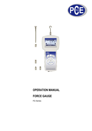
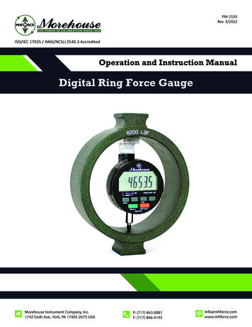
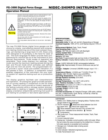
NIDEC-SHIMPO INSTRUMENTSFG-3000 Digital Force GaugeOperation ManualOperators should wear protection such as a mask and gloves in casepieces or components break away from the unit under test.Whether the unit is ON or OFF, DO NOT exceed the capacity of thegauge. NEVER exceed 150% of the rated capacity, or the load cell willbe damaged. At 110% of the rated capacity, the display will flash awarning.When mounting FG-3000 Series Digital Force Gauges, use M6 mounting screws with a maximum insertion depth of 7 mm into the gauge.Hand tighten mounting screws, DO NOT use tools. Do not use damaged clamp.Measure in line tension and compression forces only. DO NOT attemptto measure forces at an angle to the measuring shaft – damage to loadcell and/or shaft may result.Do not attempt to repair or alter this instrument. Warranty will be voidedand damage to the unit may result.Use and store within the stated temperature and humidity ranges, ordamage and failure may result.When using adapter measuring heads, do not use tools. Hand tightenonly.The ne w F G - 3 0 0 0 S e r i e s d i g i t a l f o r c e g a u g e s are thechoice f o r s i m p l e , c o s t- e f f e c t i v e t e n s i o n a n d compres sion te s t i n g . C o m b i n i n g o n e o f t h e m o s t c o m p act hous ings, y e t m a i n t a i n i n g a l a r g e b a c k- l i t L C D, t h ese unitswere d e s i g n e d t o fi t p e r f e c t l y i n t h e h a n d f o r ease ofuse. T h e m u l t i - l a n g u a g e F G - 3 0 0 0 ’ s p r o v i d e menu programm i n g f o r i n t u i ti v e s e t- u p o f t h e i n s t r u m e nt to yourdesire d r e q u i r e m e n t s . T h r e e m o d e s o f o p e r ation areselect a b l e : Tr a c k m o d e d i s p l a y s l i v e r e a d i n gs, Peakmode r e c o r d s t h e m a x i m u m r e a d i n g s e n s e d d uring thetest, a n d P r e - s e t m o d e w h i c h a c t i v a t e s u s e r definedhigh a n d l o w l i m i t s e t p o i n t s . T h e p r o g r a m m able limits pro v i d e a q u i c k v i s u a l a n d a u d i b l e i n d i c ation if atest pa s s e s o r f a i l s. I n a d d i t i o n , a c o m p a r a t or outputenable s i n t e g r a t i o n o f t h e i n s t r u m e n t i n t o y our quality sys t e m f o r r e p e t i t i v e t e s t i n g s u c h a s o n p r oductionlines.The d i s p l a y g r a p hi c s f a c i l i t a t e u s e r c o m p r ehensionand op e r a t i o n . A n a n a l o g b a r g r a p h p r o v i d e s perspec tive of c u r r e n t r e a d i n g i n c o m p a r i s o n t o t h e full scalerange. Pa s s / Fa i l i c o n s p r o v i d e a n i n s t a n t r e s ponse ofthe tes t i n g o u t c o m e w h i l e a s t o r a g e s y m b o l acknowledges w h e n a r e a d i n g i s l o g g e d . A m e n u - s electabledispla y o r i e n t a t i o n s t r e a m l i n e s s w i t c h i n g f r o m push topull te s t i n g f o r p o r t a b l e o r t e s t s t a n d a p p l i c a tions.41325967108SPECIFICATIONSAccuracy: 0.3% F.S.Selectable Units: N, kgf, ozf, and lbf. (Depending on Range)Overload Capacity: 150% of F.S. (LCD flashes beyond 110% ofF.S.)Measurement Method: Peak, Track, PresetData Sampling Rate: 1000 HzDisplay: 160*128 dot matrix LCD with BacklightDisplay Update Rate: 10 times/secondResolution: (See chart)Memory: 500 dataSet Point: Programmable high and low limits in Preset ModeBattery Indicator: Display flashes battery icon when battery islowPower: 3.6VDC 800mAH Ni-MH rechargeable batteriesBattery Life: Approximately 16 hours continuous use per fullchargeCharger / Adaptor: Universal USB/BM charger, Input: 110 240VACTemperature Effects: 0.054% per F (0.03% FS per C)Outputs: USB, RS-232; High & Low Limit NPN’sOperating Temperature: 14 to 104 F (-10 to 40 C)Storage Relative Humidity: 20 to 80%Housing: AluminumStorage Temperature: -4 to 122 F (-20 to 50 C)Oper. Relative Humidity: 5 to 95%Dimensions: 5.5 x 2.8 x 1.4” (140 x 71 x 35.5 mm)Product Weight: 0.9 lb (0.4 kg)Package Weight: 2.25 lb (1 kg)Warranty: 1 yearIncluded Accessories: AC Adaptor/Charger, USB cable, calibration cert., 6 attachments: hook, flat tip, conical tip, chisel tip,notched tip, extension shaft.LCD Screen1. Battery icon: Battery level or charging status. Flashes whengauge needs to be recharged.2. OK/OV Indicator:Measured value between low limitand upper limit;Value over upper limitValue between lower limit and 75% of lower limit3. Force icon: Indicates force direction.TensionCompression4. Test mode icon: Three measurement modes: Track, Peakand Preset5. Current meaured value6. Analog bar: Indicates current position within full scale. Whenthe bar enters the area enclosed by the dotted line, it meansfull scale capacity is exceeded and overload.7. Storage icon: Indicates data is being saved.8. System time9. Units Indicator: Selected engineering unit.10. Data Transmission icon
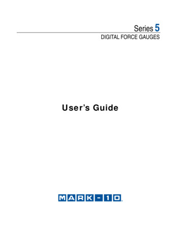
2. PREPARATION1. OPERATION1.1 Key FunctionsAll keys are capacitive touch.ON/OFF: Push for 1 second to power On or OffDuring Measurement: Store data.In Menus: Back or quit.2.1 Confirm the modelThis series force gauge has 5 ranges available, each model corresponding to the capacity and resolution shown on the last page ofthis manual. Select the appropriate model you need before use.2.2 Choose the adapterTo fit your application, this series force gauge is equipped with avariety of measuring head adapters. Select the appropriate measuring adapter prior to testing.During Measurement: Enter the menus.In Menus: Select or EnterDuring Measurement: Track mode, tares weight ofattachment. In Peak modes, resets thepeak value.In Menus: Moves selection up or increases the value.During Measurement: Changes the measure mode fromTrack, Peak or PresetIn Menus: Moves selection down or decreases thevalue.1.2 ModesTrack: Real time, live measuring mode.Peak: Peak readings will not change until a higher value is measured.Preset: User-defined set points GO/NG testing with available andvisual indicators.1.3 Menu StructureThe FG-3000 Series Force Gauge has multi-level menu interface(Table 1-3) that enables simple navigation and programming.MENUSMeasurementSUBMENUSTo mount the measuring adapter, install the adapter on thegauge’s measurement shaft. Tighten by hand. Do not tighten withany tool.NOTE: Do not use tools to tighten the adapter to the gaugeshaft. Damage to the force gauge will occur.3. Setup3.1 MeasurementThe Measurement menu contains the Unit of measure and Measurement Mode sub-menus, as shown in Fig. 3-1.SELECTIONSUnitN, kgf, lb, ozfTest ModeTrack, Peak, PresetBrowseSystemPrintSelected, AllDelete AllYes, NoDisplayObverse, ReverseAuto PowerOn, OffBacklightOn, OffKey SoundOn, OffDate/TimeCalibrationYes, NoDefaultYes, NoLanguageEnglish, Chinese,Japanese, GermanInformationModel, SN, VersionFig. 3-13.2 Select UnitsThe measuring units can be selected under this menu. Differentrange models may have different unit selection capabilities. Touch“ZERO” or “MODE” keys to shift to the next selection. Press “LOG”to cancel or touch “MENU” to confirm and exit. (Fig. 3-2)Table 1-3Fig. 3-22
3.3 Select Test Mode4.1 MemoryThe FG-3000 has 3 types of Test Modes.Track: The real time measuring mode. Under this mode, press theZERO key to tare any initial reading being displayed.Peak: In Peak mode, the maximum force will be recorded anddisplayed. Press the ZERO key to reset the peak value.Preset: Enables the setting of an upper and lower limit to compare to the measured force value. A simple GO/NG analysis isdisplayed on screen via icon indicators for quick pass/fail testing.To guarantee an accurate test, make sure to zero the display andtare any small force being displayed before beginning the test.There are two means to select your appropriate Test Mode. At thehome screen simply press the MODE key to scroll through thethree measuring modes.Fig. 4-1Memory menu contains three submenus: Browse, Print, Deleteall, as shown in Fig. 4-1.You can browse stored data or print all the data via the FG-PRINTmini-printer (sold separately). You may also delete all the recordsin the Delete all sub-menu.You can also select the mode under the Measurement menu inthe Test Mode sub-menu. See Fig. 3-3(a)4.2 BrowseIn the Browse sub-menu. The data in memory can be reviewed inthe order saved which is oldest to newest. See Fig. 4-2(a)If the Preset is selected, a new screen will pop up where you canset the Upper and Lower limits. See Fig 3-3(b)Press ZERO/UP or MODE/DOWN to scroll.Press ZERO to adjust the number and press MODE to move tothe next digit.Press MENU. A small window will pop out. Here you can selectDelete or Print. See Fig. 4-2(b).If you select Delete, a confirm window will appear asking you toconfirm. Press MENU to confirm or LOG to exit.Fig. 3-3(a)Fig. 3-3(b)Note:1) The upper limit can not exceed 110% capacity of the forcegauge.2) The lower limit must not be less than 10% of capacity.3) The upper limit must exceed the lower limitFig. 4-2(a)Fig. 4-2(b)4.3 PrintYou can print the data in memory. Enter Print. (Fig. 4-3) ChooseSelected or All.4. Saving the Measured ValueMeasured results can be stored in the force gauge’s memory. Youcan review or print the stored data at a later time.At the home screen press the LOG key to store a value. The storage icon will be displayed.The data stored is the current displayed force value in Track andPreset modes. In Peak mode it is the peak value shown on thedisplay.Fig. 4-3If Selected is chosen, the total Range of available data points willbe indicated. Adjust the value points to be printed to the right ofSelect. Fig. 4-3(a)If All is selected, a confirm window will appear asking you to confirm. See Fig. 4-3(b).3
Fig. 4-3(a)Fig. 5-1(a)ReverseObverseFig. 4-3(b)Fig. 5-1(b)4.4 Delete AllAll data points can be cleared from memory under the Delete allsub-menu (Fig. 4-4). A confirm window will appear asking you toconfirm. See Browse for details on deleting individual points oneat a time.5.2 Auto PowerThe FG-3000 has an automatic power off function. With Auto Power on, if there is no operation performed within five minutes it willpower off automatically. (Fig. 5-2)Fig. 5-25.3 BacklightThe backlight can be set to turn on or off. See Fig.5-3. Choosingthe backlight to be off will reduce the consumption of the battery.Fig. 4-45. SYSTEMUnder the System menu, the Display, Auto Power, Backlight, KeySound, Date/Time, Calibration and Default sub menus are present.Fig. 5-35.4 Key SoundThe Key Sound can be turned on or off as shown in Fig. 5-4.Fig. 55.1 DisplayThere are two display modes: Obverse and Reverse (Fig. 5-1(a)).Obverse will allow the display to be up-right with the keypad underneath, while Reverse will allow the display to be up-right withthe keypad above. Fig. 5-1(b)Fig. 5-45.5 Date/timeDate and time can be adjusted under this menu. Press ZERO toadjust the number and press MODE to move to the next digit. Fig.5-5Fig. 5-54
5.6 CalibrationBecause of the sensor material performance or the influence ofexternal factors, there may be errors of a certain level aftera period of usage.It is recommended to send the force gauge to a specialized testing organization for calibration.If you have standard force weights or other standard load and atest stand, you may utilize this function and procedure to calbratethe sensor.Fig. 5-6(d)Fig. 5-6(e)5.7 DefaultWith this function, the force gauge can be restored back to theoriginal factory settings. Only perform this function when all othertroubleshooting tactics have first been attempted.6. LanguageThe force gauge can display in various languages. Set the language as desired. See Fig. 6.Fig. 5-6(a)1) Mount the force gauge.2) Use the tare by use of the ZERO key.3) Enter Calibration sub-menu as in Fig. 5-6(a).The calibration interface is shown in Fig. 5-6(b).Fig. 67. InfoInformation about the force gauge such as model, version andserial number is provided in this menu. Fig. 7Fig. 5-6(b)4) Load a standard force. Now the value in the standard input areais just equal to the current measured value. Wait a moment for theforce to stabilize.Fig. 78. Communication PortThe force gauge has a USB for recharging and communicatingwith a PC, plus an 8 pin connection for printer connection and setpoint output. Fig. 8-1Fig. 5-6(c)5) Press ZERO and MODE to input the standard force value.6) Press MENU to enter the next calibration. Press LOG to interrupt the calibration.When 3 calibration points have been finished, a confirm windowwill pop up asking to “Save and Exit”(YES)/(NO). Fig. 5-6(d)Press ZERO or MODE to select, then press MENU.Fig. 8-1If “YES” is selected, Calibration is complete. Fig. 5-6(e)5
The RS232 serial port is used to connect the mini-printer to printthe memory data stored on the gauge.RS-232 Specifications:-Hardware Flow Control: None-Data word length: 8 bits-Stop bit: 1bit-Parity: None-Baud rate: 38400Fig. 8-28.2 Setpoint OutputTwo NPN open collector setpoint outputs are available.The internal circuit of the setpoint output is shown as Fig 8-2.Pin7 with Pin6 will be connected when an overload alarm occurs.In Preset Mode, Pin7 to Pin6 is connected when the measuredvalue exceeds the upper limit. Pin4 to Pin6 is connected when themeasured value passes below the lower limit.CAUTION: Maximum permissible voltage: pin 7 to 6, pin 4 to6 must be lower than 35V ; pin 6 to 7, pin 6 to 4 must be lowerthan 6V .Remember to remove the load after measurement. Applying aload for a long time period may affect the accuracy of the instrument.9. Maintenance9.1 MaintenanceAfter use, please keep the instrument body clean. Do not let oiland other substances persist on the body and screen so as notto damage the instrument. Remember to remove the load aftermeasurement. Applying a load for a long time period may affectthe accuracy of the instrument.9.2 ChargingWhen the battery is low, the icon “” will be displayed. Thebatteries should be charged immediately.Connect the gauge and the charger with the USB cable. Thenconnect the charger with AC socket to start charging.610. TroubleshootingAccording to the following table, review possilbe solutions forproblems encountered. Do not disassemble the gauge by yourself or attempt to repair. If you cannot resolve the fault yourself,please contact Nidec-Shimpo.FailurePossible CausesPotential SolutionsUnit will notturn onLow batteryRecharge and then reboot. If after 3-4 hours ofcharging time the batterydoes not properly hold acharge, the battery needsto be replaced. ContactNidec-Shimpo.No keysoundKey sound isturned offTurn on the key sound inmenuNo backlightBacklight is turnedoffTurn on the backlight inmenuError is toolargeThe gauge is notcalibratedCalibration of force gaugeis required. After calibration if the error remainsoutside of the specifications, sensor may bedamaged. Contact NidecShimpo to get RMA forreturn.
11. Capacity and 057
71. 2 9 7-t'[13 . 8M6P l. 04.0751 30.3.O-- - ,)3 5. 5Depth Max Bll ni L ;mm
gauge's measurement shaft. Tighten by hand. Do not tighten with any tool. NOTE: Do not use tools to tighten the adapter to the gauge shaft. Damage to the force gauge will occur. 3. SETUP 3.1 Measurement The Measurement menu contains the Unit of measure and Mea-surement Mode sub-menus, as shown in Fig. 3-1. Fig. 3-1 3.2 Select Units