Transcription
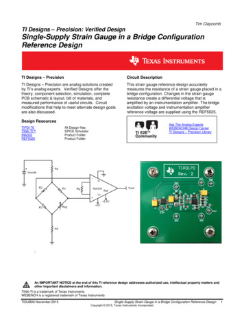
OPERATION MANUALFORCE GAUGEFG Series
2OPERATION MANUALContents:1. Introduction 32. Set 33. Safety instructions 44. Rules for handling a worn force gauge 45. Technical data 56. Keys and indicators 67. Preparing the force gauge for operation 78. General rules for use 89. Turning on the gauge 910. Description of measurement methods 1010.1 Measuring actual and peak value of a pressure/pull force 1010.2 Measurement of the mass – using the gauge as scales 1111. Connecting external devices 1412. User’s Menu 1513. Applications 1513.1 Data memory 1613.2 Comparison with threshold values MIN / OK / MAX 1914. Units 2015. Configuration 2115.1 Speed of measurement 2115.2 Auto-reset 2215.3 Print settings 2315.4 Setting parameters for the RS-232C serial connector 2415.5 LCD settings 2515.6 Selecting the menu language 2615.7 Setting date and time 2615.7 Setting date and time 2715.8 Turning the sound ON/OFF when using the keypad (buzzer) 2815.9 Automatic power OFF (Auto-OFF) 2815.9 Automatic power OFF (Auto-OFF) 2915.10 Monitoring the batteries’ charge level (Battery) 2915.10 Monitoring the batteries’ charge level (Battery) 3015.11 Reset settings 3116. Calibration 3116. Calibration 3217. Maintenance, troubleshooting and repairing minor types of damage 33
OPERATION MANUAL31. IntroductionThe FG series force gauges are designed for measuring pressure or pulling force inlaboratory, manufacturing and quality control applications.The gauge can be held in hand or mounted on a stand (using the four threadedholes at the bottom of the enclosure).The RS232C serial connector allows the measurement results to be transmitted to acomputer or a printer for further analysis or recording.2. SetThe basic set includes the following elements:1. Force gauge,2. Push tips – 4 pcs, 1 hook tip, 1 extension piece3. Power supply unit 230 V 50 Hz / 12 V; 1.25 A,5. SK-1 cord (dynamometer – computer),6. SK-1 cable,7. CD containing an operation manual and software,8. Warranty.
OPERATION MANUAL43. Safety instructionsRead carefully the safety instructions included below.Observe these instructions to avoid electrocution ordamage to the force gauge itself or other devicesconnected to the force gauge. Repairs and any necessary adjustments may only be conducted byqualified personnel. Do not use the force gauge when any part of the enclosure has beenremoved. Do not use the force gauge in potentially explosive atmospheres. Do not use the force gauge in areas with a high humidity. In the case of suspected damage to the force gauge, turn off the gauge anddo not use it until it is examined by a specialised servicing facility.4. Rules for handling a worn force gaugeAccording to the applicable regulations on theprotection of the environment, do not put wornelectronic devices in containers for common waste. When put out of operation, a worn force gauge can be delivered to bodiesauthorised to collect old electronic equipment or to the point of purchase.
OPERATION MANUAL55. Technical dataTypeMaximum force measuredReading graduation (d)AccuracyMeasurement unitsMaximum overloadOperating temperatureInterfaceAssistance softwareDisplayMeasurement functionsFG50FG20050 N (5kg)200 N (20kg)0.01 N (1 g)0.1 N (10 g) 0.4% 0.4%N, g, lb, oz, kg 120%-10 40 CRS-232CProcell Excel spreadsheetgraphic LCD 61 x 34 mmPower supplyNiMH R3 batteries (AAA size) – 6 pcs power supply unit 230 V 50 Hz / 12 V 1.2 AGauge plungerDimensionsWeight11 mm (thread M6 x 9 mm)210 x 110 x 40 mm700 g
OPERATION MANUAL66. Keys and indicatorsMain keys:ON/OFF- ON / OFF key (standby),UNIT/CLEAR - Change units / cancel selection or change a parameter value,BACKLIGHT - Turn on illumination (ECO mode),ENTER- Confirm / select an option or a digit, T - Taring / resetting (entering the current reference value to be subtracted from themeasured values in each consecutive measurement)( 0 )MENU PEAKMEMPRINTNavigation keys:- Confirm the entered parameter or select a highlighted option,- Move cursor up or increase the digit marked by the cursor,- Move cursor down or decrease the digit marked by the cursor,- Move to the next menu level or display the next option,- Move to the previous menu level or display the previous option.Function Keys:- Measure the maximum value,- Save the result to the memory, press and hold – save to memory menu,- Print result (transmission via RS-232C connector).Indicators:OFFSLW/FSTACQ-Indicates that the weighing result has stabilised,Appears after turning off the gauge using the ON/OFF key (standby),Slow/fast measurement mode,Automatically acquire measurement results.Note:Numbers are entered using the navigation keys. First, the cursor is placed in the right digit position.
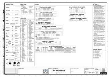
OPERATION MANUAL77. Preparing the force gauge for operationIf the force gauge has been transported from an area with lowtemperature to an area with a higher temperature, e.g. duringwinter, water may condensate on the gauge’s enclosure. In such acase, do not turn on the gauge’s power supply, as it may lead todamage to the gauge or improper operation. Before turning on thegauge, leave it for 1 hour to acclimatise.1. Take the gauge out of the case.2. Fit a measurement tip suitable for the measurements to be conducted on thegauge plunger.Tip ATip E(hook)Tip BTip CExtensionpiece FTip DIntended use of the individual tips:- tip A – measurement of surface pressure force,- tip B – measurement of point pressure force,- tip C – measurement of pressure on an axis or an edge,- tip D – measurement of edge pressure force,- tip E – hook for measuring pull force or suspending and weighing an object,- tip F – extension piece suitable for all types of above-mentioned tips.
OPERATION MANUAL88. General rules for useWhen transporting the force gauge, unscrew the measurement tip andput the gauge in the case to protect it against accidental pressure onthe gauge plunger.1. When conducting measurements by hand, make sure that the direction of themeasured force is identical with the gauge’s axis (axis of the gauge plunger).Otherwise, only a component force along the gauge’s axis will be measured.2. The gauge allows for resetting in the entire measurement range (this operation iscalled taring in the case of measuring the mass) by pressing the T(0) key.Resetting/taring does not extend the measurement range but only subtracts theentered reference value from the measured value.3. The measurement mechanism is a precision device and is sensitive to shocks andvibrations. It is not allowed to hit the measurement tip against any objects.4. Do not overload the gauge above the maximum overload value (20%).
OPERATION MANUAL99. Turning on the gaugePCE Groupwww-pce-group-europ.comPlace the gauge in the operatingposition, e.g. horizontal position (bylaying it on a table). Turn on thegauge by pressing the ON/OFF key.When necessary, plug the gauge’spower supply unit to a 230 V/50 Hzsocket and connect the power supplyunit’s plug to the gauge’s 12 Vsocket.RESETTINGThe gauge automatically tests theelectronic subassemblies and thenresets. During this operation, thegauge should remain stationary andits sensor should not be affected byany forces.CONTINUOUS MEASUREMENT0.00NAfter the resetting has beensuccessfully completed, the gaugeindicates zero.Unsuccessful resetting is signalled byan appropriate message. -- Note:It is possible to accelerate the resetting process by pressing the MENU key, whichwill recall the results from the previous resetting.If the batteries are low, leave the gauge’s external power supply unit ON until theyare fully recharged. The batteries’ charge level is signalled by an indicator in theupper section of the display.
OPERATION MANUAL1010. Description of measurement methodsThe gauge can be used to measure pressure and pull forces. In addition, whenmounted properly, it can be used as suspension scales to measure the mass.10.1 Measuring actual and peak value of a pressure/pull forceMeasuring pressure forceMeasuring pull forceBefore starting the measurement,choose a suitable measurement tip,screw it to the gauge plunger andreset the gauge in the operatingposition, e.g. horizontal position(laying the gauge on a table). Theresetting process starts automaticallyafter turning on the gauge or bypressing the T(0) key.RESETTINGCONTINUOUS MEASUREMENT0.00N -- PEAK MEASUREMENT0.10N -- To perform the measurement,indicate the force direction using anarrow in the display’s lower barsection and “ ” (pressure) or “-” (pullforce) symbol.To change the measurement from theactualvalue(continuousmeasurement) to the maximum value(peak measurement), use the PEAKkey.When measuring a force whosedirectionchanges,thegaugeindicates the value of the forceexerted in the direction in which themaximum value was last exceeded.
OPERATION MANUAL1110.2 Measurement of the mass – using the gauge as scalesWhen using an additional element (bowl, basket, etc.) for suspending an object tobe weighed, the gauge can be used to measure the mass. In the case ofmeasurements which do not require a high level of precision, the gauge can behand-held. To ensure maximum precision of the measurement, the gauge should bemounted on a stand using the four threaded holes at the bottom of the enclosure orit can be suspended using a special suspension element (option available onrequest).Since the value of the gravity force used to calculate the mass depends on thegravitational acceleration in the location where the gauge is used, the device iscalibrated for a specific value of the gravitational acceleration. The factory presetvalue is the gravitational acceleration in Gdańsk (gR 9.81415 m/s2). In the case ofsignificant differences, see the value applicable for the gauge’s shipment address.When transporting the gauge to a location where the gravitational accelerationdiffers significantly, recalibrate the gauge.The values of the gravitational acceleration for some of the Polish cities arepresented in the table below.Gravitational acceleration for selected EłkGliwiceGorzów ona 3709.810059.813139.812409.812889.811319.81190
12OPERATION MANUALMeasurementusing a hand-held gaugeMeasurement using a gaugemounted on a stand(stand available on request)Suspended weight measurement(suspension element available on request)
OPERATION MANUAL13Screw the hook tip to the gaugeplunger, suspend a bowl on thehook and place the gauge in theoperating position (as shown in thefigure). The display’s indicationswill rotate by 180o.USER’s MENU1.2.3.4.5.To change force units to massunits, press the UNIT/CLEAR orMENU key several times. Whenusing the MENU key, move thecursor to Units and press tUNITS Kilogram Gram Pound Ounce NewtonExit[kg][g][lb][oz]Move the cursor to a mass unit(kilogram or gram) and pressENTER.[N]RESETTINGReset the gauge in the operatingposition by pressing the T(0) key.Place the object to be weighed onthe bowl.CONTINUOUS MEASUREMENT0.2kg - Read the mass.
OPERATION MANUAL1411. Connecting external devicesThe force gauge is equipped with a socket for an external power supply unit andRS232C serial connector for a printer or a computer.ZASILACZRS232C1 - RxD2 - masa3 - TxD4 - NCPLZASILACZmasaENPOWER SUPPLY UNITearthDescription of the data transmission protocol when working with a computer(LonG):The scales transmit the result as follows (8 bits, 1 stop, no parity, 4,800 bps):Computer Gauge: initiating signal S I CR LF (53 h 49 h 0Dh 0 Ah),Gauge Computer: gauge indication according to the following format (16 bytes).Description of individual 123 45 910111213141516- “-“ or space- space- digit or space- digit, comma or space- digit- space- k, l, c, p or space- g, b, t, c or %- space- CR- LF
OPERATION MANUAL1512. User’s MenuThe User’s Menu includes all functions and options necessary to operate the gaugeor extend its functionalities.USER’s ationExitTo use the options of the USER’sMENU, use the MENU key. Move thecursor to the desired option andpress ENTER.The menu includes:1. Applications – advanced measurement functions,2. Units – select measurement units,3. Configuration – set the gauge’s mode of operation,4. Calibration – adjust the measurement accuracy using an external standard ofmass.5. Exit.13. ApplicationsThis selection includes the following functions to effectively assist you with themeasurement:- memory operations and data analysis,- comparison with two threshold values (MIN / MAX).USER’s ationExitAPPLICATIONS Data memory Threshold valuesExitMove the cursor to Applications andpress ENTER.Move the cursor to the desiredapplication and press ENTER.
OPERATION MANUAL1613.1 Data memoryThe Data memory application allows for the following:- presentation of the collected measurements, saving, reading, erasing memory(Statistics),- selecting the mode for collecting data,- exit.USER’s ationExitMove the cursor to Applications andpress ENTER.APPLICATIONS Data memory Threshold valuesExitMove the cursor to Data memoryand press ENTER.APPLICATIONS1.2.3.4.5.StatisticsMode MANUAL AUTO Number of samples100Sampling time0.1 secExit ENTERSetting the mode for collectingdata:- MANUAL – each time after MEM ispressed,- AUTO – automatically at specifiedintervals.APPLICATIONS1. Statistics2. Mode MANUAL AUTO 3. Number of samples1004. Sampling time0.1 sec5. ExitAfter selecting AUTO, enter thenumber of samples (max 100) andsampling time (0.1 99.9 s.).APPLICATIONS1.2.3.4.5.StatisticsModeNumber of samplesSampling timeExitAUTO1000.1 sec ENTERTo start the collection ofmeasurements, exit the menu andpress MEM several times or pressMEM for automatic save. When inthe automatic save mode, press andhold MEM to go to the data savemenu.
OPERATION MANUAL17Presentation of collected measurements (Statistics)The Statistics option allows for the following forms of presentation of the collecteddata: PRINT – transmission to a printer, HISTOGRAM – bar graph, GRAPH – graph with a time axis.USER’s ationExitMove the cursor to Applications andpress ENTER.APPLICATIONS Data memory Threshold valuesExitMove the cursor to Data memoryand press ENTER.DATA MEMORY1.2.3.4.StatisticsModeNumber of samplesSampling time6. ExitMove the cursor to Statistics andpress ENTER.AUTO1000.1 secSelect one of the options from thelower menu bar:- PRINT – transmission to a printer,- HISTOGRAM – bar graph,- GRAPH – graph with a time axis.- RESET – erases the entire memory,- DELETE – deletes a selectedmemory file.StatisticsQuantitySumAverageMAXMIN100990 g9g12 g8g PRINT HISTOGRAM GRAPH SAVE READ RESET DELETE EXIT HISTOGRAMIndicators L. . provide thesize of the bar indicated by the arrow.To move the arrow (scroll thegraph), use the and keys.MINMAX L01 8 ENTER
OPERATION MANUAL18Save, read, erase memory (Statistics)The Statistics option allows for the following: SAVE – saves the data currently presented, READ – reads a file from the memory, RESET – erases the data currently presented, DELETE – deletes a selected data file.USER’s ationExitMove the cursor to Applications andpress ENTER.APPLICATIONS Data memory Threshold valuesExitMove the cursor to Data memoryand press ENTER.DATA MEMORY1.2.3.4.5.StatisticsModeNumber of samplesSampling timeExitStatisticsQuantity100Sum990 gAverageMAXMINMove the cursor to Statistics andpress ENTER. AUTO 1000.1 secThe following options (lower bar)will appear:- .- SAVE – saves the measurementscurrently presented,- READ – reads a measurementfile,- RESET – erases the memory,- EXIT – exits the option.Select the SAVE option.9g12 g8g PRINT . SAVE READ RESET EXIT SAVE DATA FILE01 FILE02 .FILE08 Select a file (FILE) to be saved. ENTERThe default file name includesdate and time. Confirm thedefault file name or enter anothername using the , , and keys.SAVE DATA2009-12-17 10:00 FILE02 . FILE08 ENTER
OPERATION MANUAL1913.2 Comparison with threshold values MIN / OK / MAXThis selection includes the following functions to effectively assist you with themeasurement:- memory operations and data analysis,- comparison with two threshold values (MIN / MAX).USER’s ationExitMove the cursor to Applications andpress ENTER.APPLICATIONS Data memory Threshold valuesExitMove the cursor to Threshold valuesand press ENTER.THRESHOLD VALUES1. Status2. MIN3. MAX4. Buzzer5. Exit ON OFF 1.000kg2.000kgMODE1 ENTERActivate the comparison by settingStatus to ON:- enter the MIN value – lowerthreshold,- enter the MAX value – upperthreshold.Select the option for soundsignalling (Buzzer):- MODE1 – short signal uponexceeding MIN, long signal uponexceeding MAX,- MODE2 – interrupted signalbelow MIN, above MAX –continuous signal, for OK – nosignal.CONTINUOUS MEASUREMENTOK0.00N -- Exit the menu, start themeasurement and observe the MIN,OK and MAX indicators on thegauge’s display.
OPERATION MANUAL2014. UnitsThe following units are available to the user:- kilogram (kg)- gram (g)- Pound: 1 lb 453.592374 g- ounce: 1 oz 28.349523 g- Newton: 1 N 0.10197 kgTo change the units, press the UNIT/CLEAR or MENU key several times.USER’s ationExitPress the MENU key, move thecursor to Units and press ENTER.UNITS Kilogram Gram Pound Ounce NewtonExitMove the cursor to the desired unitand press ENTER.[kg][g][lb][oz][N]ENTER
OPERATION MANUAL2115. ConfigurationThis selection includes all options for setting the gauge’s modes of operation.USER’s ationExitMove the cursor to Configurationand press ENTER.CONFIGURATION1. Speed of measurement2. Auto-reset3. Print settings4. RS-232C settings5. LCD settings6. Language7. Date and time8. Auto-OFF9. Battery10. Default settings11. ExitMove the cursor to the desiredoption and press ENTER.15.1 Speed of measurementTo obtain clear measurement results, it is recommended to adjust the speed ofmeasurement to the dynamic properties of the measured object.USER’s ationExit1.2.3.4.5.Press ENTER to select one of theoptions:- SLOW – slow measurement,- FAST – fast measurement.CONFIGURATIONSpeed of measurementAuto-resetPrint settingsRS-232C settingsLCD settingsSPEED OF MEASUREMENT SLOW FASTExitENTER
OPERATION MANUAL2215.2 Auto-resetWhen activated, this option automatically maintains zero indications on the gauge,if the gauge’s sensor is not affected by any external force or if the zero indicationwas produced by pressing the T(0) key. The range of values (calculated in thegauge’s reading graduation near zero) subject to the reset must be entered underthe Range option (3 digits).USER’s MENU1.2.3.4.5.Use the navigation keys andENTER to select Status and one ofthe following options:- ON – auto-reset ON,- OFF – auto-reset ONFIGURATION1.2.3.4.5.Speed of measurementAuto-resetPrint settingsRS-232C settingsLCD settingsNext, select Range and use , , , and ENTER to enter theauto-reset range (in readinggraduation).AUTO-RESET1. Status2. Range3. Exit OFF 002d ENTERAUTO-RESET1. Status2. Range3. Exit ON OFF 2 d ENTER
OPERATION MANUAL2315.3 Print settingsAccording to the requirements of GLP procedures, it is possible use an externalprinter to produce print-outs from the gauge including text information.USER’s ationExitUse the navigation keys andENTER to select Print settings andthe suitable print components.CONFIGURATION1. Speed of measurement2. Auto-reset3. Print settings4. RS-232C settingsPRINT SETTINGSID1, ID2, ID2 – text strings (up to Heading Date Time ID1 ID2 ID3 Number20 characters) forming the lines ofthe print-out, entered using thegauge’s navigation keys. ENTERTo enter the characters, select IDusing ENTER and press . Thecharacters are entered using thenavigation keys and . To movethe cursor to the consecutivepositions, use and . Toconfirm the entered string, pressENTER. To delete a character,enter space.PRINT SETTINGS Heading Date Time ABCD ID2 ID3 ENTER
OPERATION MANUAL2415.4 Setting parameters for the RS-232C serial connectorThe parameters of the serial connector must be suitable for the device receiving thesignal.USER’s ationExit1.2.3.4.5.Parameters to be set:CONFIGURATIONSpeed of measurementAuto-resetPrint settingsRS-232C settingsLCD settingsRS-232C1. Baudrate2. Bits3. Parity4. Sending5. Exit48008-bitnoneNORMAL ENTERRS-232C1. Baudrate48002. Bits8-bit3. Paritynone4. Sending NORMAL NO STB AUTOSTB CONTIN. 5. Exit ENTER- Baudrate – transmission andreceiving rate (4,800 115,200bps),- Bits – number of bits whichconstitute a character (7 or 8 bits),- Parity – control of parity (nocontrol, even – confirmation ofparity, or odd – confirmation ofodd parity),- Sending – transmission methodduring measurement:- NOCAL – after using the PRINTkey, with stable result,- NOSTB – after using the PRINTkey, irrespectively of the resultstability,- AUTOSTB – automatically afterthe result has stabilised,- CONTIN.–continuoustransmission, approx. every 0.1s.
OPERATION MANUAL2515.5 LCD settingsThis option adjusts the gauge’s display to external lighting conditions.USER’s MENU1. Applications2. Units3. Configuration4. Calibration2. ExitUse the navigation keys andENTER to select LCD settings.Next, use , and ENTER to setthe contrast at which the display isbest legible.CONFIGURATION1.2.3.4.5.Speed of measurementAuto-resetPrint settingsRS-232C settingsLCD settingsSETTINGS1. Contrast2. Illumination3. Direction4. LCD time5. Exit ON OFF ENTERSETTINGS1. Contrast 2. Illumination ON OFF ECO BAT 3. Direction4. LCD timeOFF5. Exit ENTERSETTINGS1. Contrast2. Illumination3. Direction4. LCD time5. Exit ECO AUTO UP DOMN OFF ENTERWhen setting Illumination, selectone of the following options:- OFF – illumination OFF,- ON – illumination continuouslyON,- ECO – to illuminate, use theBACKLIGHT key,- BAT – illumination is turned offafter 30 seconds to save thebatteries.The DIRECTION option is used forselecting the display’s direction:- AUTO – automatic rotation of thedisplayed image,- UP – standard direction,- DOMN – inverted image.The LCD TIME option displays thedate and time during measurementin the display’s upper bar.
OPERATION MANUAL2615.6 Selecting the menu languageThree menu languages are available: PL – Polish, ENG – English, DE – German.USER’s MENU1.2.3.4.5.Use the navigation keys andENTER to select Language. Toselect one of the available menulanguages, use the , keys TER.CONFIGURATION.4. RS-232C settings5. LCD settings6. Language7. Date and time8. Auto-OFFTo enter a new code (NEW), selectthe PIN option. When entering anew code, type in the same numbertwice (message: REP.).LANGUAGE1. Language2. Exit PL ENG DE ENTER
OPERATION MANUAL2715.7 Setting date and timeThis option is used for entering the current date and time. Access to this setting issecured by the PIN code.USER’s MENU1.2.3.4.5.Use the navigation keys andENTER to select Date and time. If aPIN has already been entered(other than 0), after selecting Timeor Date, the cursor will move to thePIN option, where a correct 4-digitPIN has to be entered. To enter thecorrect digits, use the , , , keys and tCONFIGURATION3. Print settings4. RS-232C settings5. LCD settings6. Language7. Date and time8. Auto-OFFTo enter a new code (NEW), selectthe PIN option. When entering anew code, type in the same numbertwice (message: REP.).DATE AND TIME1. Time2. Date3. PIN4. Format5. Exithh:mm:ssyyyy-mm-dd0 EU USA The FORMAT option allows for theselection of the date format onprint-outs.ENTER
OPERATION MANUAL2815.8 Turning the sound ON/OFF when using the keypad (buzzer)This options turns ON or OFF the sound signalling that a key on the keypad hasbeen pressed. When the sound is turned on, the user usually does not applyexcessive force when pushing the keys.USER’s MENU1.2.3.4.5.Use the navigation keys andENTER to select Keypad andBuzzer, and one of the followingoptions:- ON – sound ON,- OFF – sound ONFIGURATION3. Print settings4. RS-232C settings5. LCD settings6. Date and time7. KeypadAUTO-OFF1. Buzzer2. Exit ON OFF ENTERAUTO-OFF1. Buzzer2. Exit ON ENTER
OPERATION MANUAL2915.9 Automatic power OFF (Auto-OFF)This option allows for an automatic cut-off of the gauge’s power supply to save thebattery’s energy.USER’s MENU1.2.3.4.5.Use the navigation keys andENTER to select Auto-OFF andStatus, and one of the followingoptions:- ON – the power is turned off after5 minutes, the indications remainunchanged,- BAT – the power is turned offwhen the battery is low,- OFF – the power is not nExitCONFIGURATION3. Print settings4. RS-232C settings5. LCD settings6. Date and time7. Auto-OFFAUTO-OFF1. Status2. ExitOFF ENTERAUTO-OFF1. Status:2. Exit OFF BAT ON ENTER
OPERATION MANUAL3015.10 Monitoring the batteries’ charge level (Battery)This option is used for reading the charge level of the batteries and allows for thecharging to be turned off to protect ordinary batteries, if such batteries are usedinstead of rechargeable batteries.Charging ordinary batteries used instead of rechargeable batteriesmay lead to major damage to the gauge.USER’s MENU1.2.3.4.5.Use the navigation keys andENTER to select Battery andCharging, and one of the followingoptions:- ON – charging ON,- OFF – charging ONFIGURATION5. LCD settings6. Language7. Date and time8. Auto-OFF9. BatteryBATTERY1. Charging2. Charge level3. ExitOFF80% ENTERBATTERY1. Charging2. Charge level3. Exit OFF ON 80% ENTER
OPERATION MANUAL3115.11 Reset settingsThis option restores factory settings (default settings) for all options.USER’s MENU3.4.5.6.7.Use the navigation keys andENTER to select Reset settings andthe option s a result of restoring factorysettings, the gauge will reset andstart continuous measurement.CONFIGURATION.7. Date and time8. Auto-OFF9. Battery10. Reset settingsRESET SETTINGSRestore default settings?NOYES ENTER
OPERATION MANUAL3216. CalibrationTo calibrate the gauge, select the method of applying load. For this purpose, use astand or suspend a standard of mass on the gauge.Reset the gauge without load usingthe T(0) key.Use the navigation keys andENTER to select Calibration andUSER’s MENULoad.6. Applications7. Units8. Configuration9. Calibration10. ExitSelect the load depending on thestandard of mass. The . optionallows for entering any value.CALIBRATION1.2.3.4.5.CalibrationLoad 5kg 20kg 10kg . g 9.81416m/s2Geographical locationExit ENTEREnter the gravitational accelerationto correctly convert mass (kg) intoforce (N).If the exact “g” value is notknown, enter the parameters of thegeographical location (latitude andabove mean sea level). The “g”valuewillbecalculatedautomatically.Apply the standard of mass to thegauge.Use the navigation keys andENTER to select Calibration andwait until the calibration process iscompleted.CALIBRATION1.2.3.4.5.CalibrationLoadg 9.81416m/s2Geographical locationExit 5kg ENTER
OPERATION MANUAL3317. Maintenance, troubleshooting and repairing minor types of damage1. Keep the gauge clean.2. When using the force gauge, make sure that no contamination gets between thegauge plung
connected to the force gauge. Repairs and any necessary adjustments may only be conducted by qualified personnel. Do not use the force gauge when any part of the enclosure has been removed. Do not use the force gauge in potentially explosive atmospheres. Do not use the force gauge in areas with a high humidity.