Transcription
GC 15100WarningForw ard this manual to the person responsiblefor Installation, Operation and Maintenance ofthe product described herein. Without accessto this information, faulty Installation, Operationor Maintenance may result in personal injury orequipment damage.Installation, Operationand Maintenance ofEaton/Geislinger Damping TorsionalFlexible CouplingCaution:Use Only Genuine Airflex Replacement PartsThe Airflex Division of Eaton Corporat ion recommends the useof genuine Airflex replacement parts. The use of non-genuineAirflex replacement parts could result in subst andard productperf ormance, and may void your Eaton w arranty. For optimumperformance, contact Airflex:Phone: 216-281-2211Toll Free: 800-233-5926FAX: 216-281-3890September, 1994204041PDF Format Copyright Eaton Corp. 1994 All rights reserved.
Table of Contents1.0 INTRODUCTION. . . . . . . . . . . . . . . . . . . . . . . . . . .31.1 Description . . . . . . . . . . . . . . . . . . . . . . . . . . . .1.2 How it Works . . . . . . . . . . . . . . . . . . . . . . . . . . .1.3 Alignment . . . . . . . . . . . . . . . . . . . . . . . . . . . . .3342.0 INSTALLATION . . . . . . . . . . . . . . . . . . . . . . . . . . . .62.12.22.32.42.52.6Preparation . . . . . . . .Machinery Alignment . . . .Coupling Installation . . . .Oil Filling/Vent ing/PressurizedOil Filling/Prefilled . . . . .Basic Mark . . . . . . . .3.0 OPERATION.667788. . . . . . . . . . . . . . . . . . . . . . . . . . . . .93.1 Start Up . . . . . . . . . . . . . . . . . . . . . . . . . . . . . . 93.2 Post Trial Checks . . . . . . . . . . . . . . . . . . . . . . . . . 93.3 Inspection . . . . . . . . . . . . . . . . . . . . . . . . . . . . . 104.0 DISASSEMBLY . . . . . . . . . . . . . . . . . . . . . . . . . . . . 104.14.24.34.44.54.64.7Preparation . . . . . . . . . . . .Splined Hub Removal and Inspect ionSpring Packs . . . . . . . . . . .Mount ing Flange and Side Plat es . .Disassembly of the Out er Member .Circularit y Adjust ment . . . . . . .Coupling Assembly . . . . . . . . .5.0 ORDERING INFORMATION AND TECHNICAL ASSISTANCEGC 15100 (PDF Format)September, 1994.10101112121212. . . . . . . 14 Copyright Eat on Corp., 1994. All right s reserved.
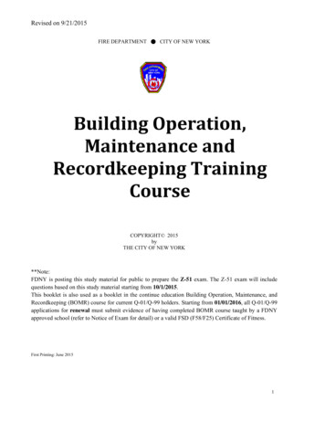
Prefilled Geislinger Torsional CouplingItem1DescriptionMounting FlangeItem11DescriptionHex Head ScrewItem20Description" O" Ring2" O" Ring12Belleville Washer21" O" Ring Carrier3Cover13Side Plat e22" O" Ring4" O" Ring14Hex Head Screw23" O" Ring5End Cover15Retainer Ring24Splined Hub6Hex Head Screw16Hex Head Screw25Dip St ick7Belleville Washer17Belleville Washer26Copper Washer89Hex Head ScrewBelleville Washer1819" O" RingEnd Plat e2728Hex Head ScrewBelleville Washer10Tensioning Ring Sub-assemblyFigure 1GC 15100 (PDF Format)September, 19941 Copyright Eat on Corp. 1994 All right s reserved
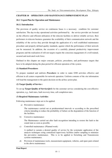
Pressurized Geislinger Torsional ion1Mount ing Flange9Belleville Washer17Washer2End Cover10Tensioning Ring S/A18Socket Head Screw34Oil InletSnap Ring1112Hex Head ScrewBelleville Washer1920WasherCover5" O" Ring13Side Plate21Splined Hub6" O" Ring14Oil Pipe22Side Plate7" O" Ring15Compression Spring28Hex Head Screw8Hex Head Screw16Socket Head Screw29" O" -RingFigure 2GC 15100 (PDF Format)September, 19942 Copyright Eat on Corp. 1994 All right s reserved
INTRODUCTIONThroughout this manual there are a numberof HAZARD WARNINGS that must be readand adhered to in order to prevent possiblepersonal injury and/or damage to the equipment.Three signal w ords " DANGER" , " WARNING" ,and " CAUTION" are used to indicate theseverity of the hazard, and are preceded bythe safety alert symbol.Denotes the most serious injuryhazard, and is used w hen seriousinjury or death WILL result frommisuse or failure to follow specificinstructions.1.1.2Eaton/Geislinger Couplings meet t hedemands not only of the internalcombust ion engines but ot her machinerysuch as pumps, compressors and turbines.1.1.3The characteristics of t he coupling, w ithrespect to damping and elast icity, can beadapted to meet t he needs of mostinst allations. The coupling has axialclearance up to t he limits show n on thedraw ing. Axial vibrations are not t ransmitted from t he prime mover t o the drivenmachine. The coupling also permits paralleland angular misalignment s w it hin specifiedlimits.1.1.4Currently there are t hree different couplingdesigns. They are designat ed Type " N" ," H" , " U" . Type " N" is t he design t ype usedw ith non reversible engines. Type " H" isthe semi reversible type, capable ofcontinuously t ransmitt ing one half of thecoupling’ s rated torque in t he reversedirection. Type " U" is t he reversible t ype,capable of transmitting t he coupling’ s rat edtorque in either direction of rot ation.1.2How It Works1.2.1The coupling is designed so that a w idevariety of adaptations can be provided tobot h a pow er source, such as a dieselengine, and to t he load, such as a gearreducer. In all cases, t he f unct ioning of thecoupling remains the same.1.2.2The entire coupling is made of st eel exceptfor the o-rings w hich seal the oil. Ref er toFigures 1 and 2 for the major componentsof a st andard design. Figure 2 is apressurized oil t ype. Figure 1 a pre-filled oilcoupling. NOTE: The follow ing numberreferences are f rom Figure 1. The mountingflange (1) and the splined hub (24) serve asthe interface members betw een a pow ersource and a load. The orientation of t heseitems in ref erence to " input " and " output"can vary w ith t he specif ic application.1.2.3The heart of the coupling is t he spring pack(10). This elast ic component consist s oftw o or more springs, w hich can bedesigned to yield various stiff ness. Thespring packs are arranged radially w it hinthe torsion ring subassembly. The outerends of the pack are clamped betw eenthe spring spacers. Clamping force isprovided by pressing a tensioning ring overthe assembly of spring packs and springspacers.Used when serious injury or deathMAY result from misuse or failure tofollow specific instructions.Used when injury or product/equipment damage may result from misuse orfailure to follow specific instructions.It is the responsibility and the duty of all personnel involved in the installation, operationand maintenance of the equipment on w hichthis device is used to fully understand the,andproceduresby w hich hazards are to be avoided.1.1Description1.1.1The Eaton/Geislinger Torsional Couplinghas been designed to economically solvet orsional vibration problems in enginedrives. The combination of highly elast icleaf springs w ith viscous damping by oildisplacement ensures t hat crit ical speedsare moved out side of the engine speedrange and that remaining torsionalvibrations are eff ectively damped. Thew idest engine speed range free of vibrationperiods and dangerous resonances ist hus obtained. Furthermore, use of t hesecouplings w ith their high dampingcharacterist ics result in low er st resses int he engine driven shafts and gears as w ellas in the crankshaf t.GC 15100 (PDF Format)September, 19943 Copyright Eat on Corp. 1994 All right s reserved
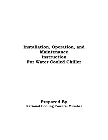
TensioningRingFigure 3The Eaton/Geislinger coupling ismanufactured in t he categories of" prefilled" Fig. 1, and " pressurized" Fig. 2.This descript ion refers to the type of oilsupply that is used in the operation of thecoupling. It is important to note t he style ofthe unit f or a specific application, becauseof the dif ferent installation and maintinanceprocedures that may be required.September, 1994If no continuous oil supply is available, aprefilled type coupling Fig. 1, can be used.1.3ALIGNMENT1.3.1Axial changes in length caused by thermalexpansion of adjoining machinery areabsorbed by the amount of allow able axialmovement that is show n on the couplingsassembly draw ing.Ambient operating temperature limitsare: -4 oF to 212 oF (-20 oC to 100 oC)When the tensioning ring subassembly isrotated relative to the splined hub, t he leafsprings in t he spring packs w ill flex, forcingthe oil t o flow . By this action, the relativemovement is " braked" and t he movement(such as vibration) is damped. The springspacers also serve as stops to preventoverstress of the leaf springs. Therefore thecouplings can be approved for ice classcertification f or marine applications w ithoutany modif ication.GC 15100 (PDF Format)1.2.7Oil filledcavit ies1.2.3.1 The tension ring subassembly(10), consisting of the spring packs, spring spacers, sideplate, spacer ring and tensioning ring, isbolt ed t o the mounting flange (1). The tipsof the spring packs’ longest leaves areretained in the spline grooves of the splinedhub (24). Betw een the spring packs, springspacers, and splined hub, cavities existw hich are f illed w ith oil See Figure 3.1.2.5A pressurized oil supply at the coupling inletis required to provide proper lubrication andfunction of the coupling. The oil supply cancome from either an " input" or " output"connection, according to the designrequirement. Any engine or gearbox oilgrade SAE30 or SAE40 can be used. SeeFig. 2.Spacer RingSpringSpacer1.2.41.2.641.3.2The coupling can also w ithstand paralleland angular misalignment. Maximumangular misalignment for the standardcoupling is /- .200 degrees (3,5 mrad),how ever refer to t he specif ic draw ing toverif y t he actual angular misalignment forthat part icular coupling. If both parallel andangular misalignment exist betw eenadjoining shaft s, capabilities w ill be reducedproportionally t o one anot her.1.3.3If ext reme misalignment capacit ies arerequired or if the corresponding reactionforces should be a minimum, the couplingcan be combined w ith a Geislinger flexiblelink. Contact Eaton/Airf lex for exact details.1.3.4The draw ing f or a typical coupling show smaximum parallel misalignment (show n asradial misalignment), maximum angularmisalignment. See Figure 4 f or a typicaldraw ing example, how ever, actualmisalignment capabilities are show n eachparticular draw ing for individual applicat ions.1.3.5A combination of vertical and horizontalparallel alignment readings and maximumangular alignment readings are used t o plota specific location on a triangle graph. SeeFigure 5. These readings must f all w ithinthe triangle to be w ithin t he capability athat part icular coupling. Copyright Eat on Corp. 1994 All right s reserved
1.3.6The follow ing formula applies for maximumparallel (radial) misalignment:2Angularreadingsrecorded at 20"diameter2V HMax. off set .020" Parallel readingsrecorded from sideplate rim.Example: (Reference Fig.4.)Max. off set .020"Horizontal offset reading 0.0025" (0.005)TIRVertical offset reading 0.003" (0.006)TIR0.003"0.0025"2.003 .00252 .0039"Plot .0039" on parallel side oftriangle(Fig.5).1.3.7Figure 4The typical maximum angular misalignmentcapability is /-0.2 or 1" x TAN0.2 .0035" /inch x dia. measured.Example: Maximum gap.0035x20" dia. .070" max.20" dia.faceUse misalignment tolerances fromdraw ing for that individual couplingonly.0"MAX. offsetfrom angularcalculat ion0.070" .006" .005"Combinationfalls w it hintriangleAngular .011"Maximum gap is .011" , plot on triangle.Airflex/Geislinger Couplings are notdesigned for intentional misalignment.The above examples are for checkingexsisting installations only. For newapplication it is imperative to achievethe best alignment possible formaximum coupling service life andperformance.011"0.000"Parallel0.000".0039"MAX. off set.020" (0.040" TIR)see draw ingFigure 5GC 15100 (PDF Format)September, 19945 Copyright Eat on Corp. 1994 All right s reserved
2.0INSTALLATION2.2Machinery AlignmentNote: Refer to section 1.3 for alignmentinst ruction.Only qualified maintenance personnelshould install, adjust or repair thesecouplings. Faulty workmanship willresult in unreasonable exposure tohazardous conditions, injury or severedamage to the mechanism.Before performing any w ork, studythis manual and assembly drawingspertaining to your specific model.DO NOT RISK INJURY - FOLLOW THEINSTRUCTIONS.2.1Preparation2.1.1.1 Check all oil f eed and return holes in thecomponents of pressurized couplings. Theseholes must be free of dirt or any foreignmaterial to ensure free oil flow .2.2.1.4 Thoroughly clean the O.D. and flange faceof the side plate of the coupling. Alignmentreadings w ill be t aken on these surfaces.Check the rubber seals to be used in matingf langes if used. These seals must not bedamaged t o ensure that t here w ill be no oilleakage. For ease of assembly, t hese sealsshould be coated w ith grade SAE30 orSAE40 engine or gearbox oil.2.2.1.5 Parallel Alignment: Rot ate the shaft w it hthe mount ed indicat or assembly and takeparallel alignment readings off t he O.D. ofthe movable shaft. If both shaft s can bemat ch-marked and rotated together, thealignment readings are less influenced byany surface irregularities or hub eccentricity.Check the mat ing hub and mounting f langesf or match marks that may be used. Thesemarks must be matched w hen the flangesare assembled to each other. Remove allnicks and burrs and clean mating surf aces.September, 1994Thermal grow th of t he driving and drivenmachinery and the foundations to w hichthey are mounted, should be considered inthe running condit ion. The suppliers’ ofthese component s should be consultedfor recommended alignment procedures.Compensation should be made so that t heshafts run t rue to each other underoperat ing condit ions w ithin t he capacitiesof the coupling w hich are show n on theassembly draw ing.2.2.1.3 Fabricate a rigid bracket for supporting adial indicator and attach to the shaft w hichis easiest to rotate.2.1.1.2 Grade SAE 15W-40 oil should be used in allprefilled unit s, filled to the level on dipst ick.GC 15100 (PDF Format)2.2.22.2.1.2 One shaft w ill be considered fixed oranchored, and w ill not be moved or shiftedfor alignment. The shaf t to be adjusted oraligned is called the moveable shaft . Checkfor any axial movement of both shaf tsbefore starting the alignment procedure.Water, especially seawater, must notbe mixed with oil to avoid damage tothe coupling.2.1.3The misalignment of t he adjoining shafts(parallel, axial, or angular) must not, at anyoperat ing condit ion, exceed the valuesshow n on the assembly draw ing, for thespecific coupling. It is VERY desirable tokeep misalignment to a minimum under alloperat ing condit ions and temperatures.2.2.1.1 In most cases, parallel and angularmisalignment are present. This requiresthat tw o sets of measurements must beobt ained(see section 1.3). One f or parallelland t he other for angular. The combinat ionof these readings must fall w ithin thetriangle (see figure 4).The coupling must not be operatedw ithout being oil filled to avoiddamage to the components.2.1.22.2.16 Copyright Eat on Corp. 1994 All right s reserved
Angular Alignment: Measure the gapbetw een t he f ace of the flange on the fixedshaft and t he f ace of the flange on themovable shaft w ith an inside micrometer.The readings should be takenat an approximat ely equal distance f rom the shaftcenter, measuring as close to the out side ofthe flanges as possible. Take 4 readingsominimum 90 apart .Axial positioning: The actual dimension ofthe gap measured betw een t he f langes inthe angular alignment procedure mustmat ch t he length over the coupling flangesas specified on the assembly draw ing. Thisspecification must be verif ied t o a toleranceof .039" ( 1mm) -.000. An out oftolerance dimension could cause damage t othe " O" ring (20) or End Cover (5).Note: A machined spacer may be includedto compensate for axial diff erences2.2.2Figure 6Shim and shift the base of t he moveableshaft to correct the misalignment. Aftertightening the base, recheck the alignmentand correct if necessary. Dow el the baseinto position af ter sat isf actory alignmenthas been achieved.2.3Coupling Installation2.3.1To accommodate lif ting devices (eye bolts,slings) t hreaded holes are provided in themount ing flange (1), and splined hub (24).The oil vent holes in the side plat e may beused to aid lifting f or couplings up t o size" 72" .2.3.2To gain additional clearance for installat ionand removal of the coupling betw eenadjoining shaf ts, the hub may be pushedinw ard. This must be done carefully toavoid damage to t he " O" rings (20) on thesplined hub (24).2.3.3Check t he initial alignment accuracy bymeasuring the radial clearance " S" betw eenthe splined hub (24), and t he side plate(13). Several readings should be takenaround t he ent ire circumference of the hub,see Figure 6. The specific couplingassembly draw ing show s the upper andlow er limits of the clearance.The coupling must not be operatedwithout being filled with oil or damageor excessive wear to the internal partswill occur.September, 1994Oil Filling/Venting/Pressurized2.4.1A pressurized oil supply at the coupling inletis required to provide proper lubrication andfunction of the coupling. The oil supply cancome from either an " input" or " output"connection, according to the designrequirement. Any engine or gearbox oilgrade SAE30 or SAE40 can be used. SeeFig. 2.A minimum oil supply pressure isrequired to transmit the maximumdamping torque in the couplingwithout cavitation. This is acalculated value for an individualcoupling. Refer to the exact Airflexdrawing for this value.Note: O-ring carriers (21) if applicable,should be concentric w ith retainer ring (15)prior to checking clearance " S" .GC 15100 (PDF Format)2.4Oil inlet temperature should notexceed 140 oF ( 60 oC) to avoidcoupling overheating and damage toseals.7 Copyright Eat on Corp. 1994 All right s reserved
2.4.2To f ill t he coupling w it h oil, rotate t hecoupling until one of t he vent screw s (27)in t he side plate (13) is in t he up position.Remove the screw and w asher.2.4.3Use the engine or gearbox lubrication pumpto pump oil into the coupling. The couplingis properly vented and filled w hen oil beginsto flow from the vent hole.2.4.4Reinstall the vent screw w ith the Belleville w asher (4) w ith Loctite #680 applied tobot h sides of the w asher for sealing. Checkthe coupling for any oil leaks.2.5Oil Filling/Prefilled2.5.1Prefilled couplings are f urnished w ith aninitial charge of oil by the factory. Theproper oil level must be verified before thecoupling is put int o service.2.5.2To check the oil level, bring the oil dipstick, (25) on Figure 1, rod int o the topposition. The correct reading is obtained byplacing t he rod into the oil reading cavityw ithout engaging the screw t hreads.2.5.32.6.2For the purpose of marking and latermeasuring, a marking bracket (21) ismounted to the side plat e (15) and reachesover the splined hub flange. See Figure 7.The t w o parallel faces of t he t ip of thebracket are the marking and measuringedges.2.6.3Bring t he system into a slow rotation by using the turning gear and mark t he splinedhub flange w ith a marking tool (see Figure7), using the tip of the bracket (21) as aguide, w hile the coupling is turning.SplinedHub FlangeThe dip stick maximum oil level mark is theline w hich represent s 90% of the fullcapacity. A minimum oil level mark is theline w hich represent s 75% of full capactity.Figure 72.6.3.1 Stop t he rotation and reverse. Mark thesplined hub flange using the opposit e sideof the tip of the bracket as a guide, w hilethe coupling is turning. This effectivlymeasures t he backlash or clearancebetw een t he spring tips and hub grooves.Do not overfill prefilled couplings.2.5.4Add SAE 15W-40 oil as necessary unt il t hemaximum mark is reached. Remove thevent screw (27) to assist in this process.Screw the oil rod w it h sealing w asher intothe threaded hole to form an oil t ight fit .Check t he coupling for any oil leaks.2.6.4These marks must be especially durable,as every mark obtained later is t o becompared w ith t he f irst or " basic mark" .Check t he " basic mark" by repeating theabove procedure of Sect ions 2.6.3 and2.6.3.12.6Basic Mark2.6.52.6.1Whenever a coupling is being installed,w hether new , repaired or reconditioned, itmust be marked w ith a " basic mark" w hichrepresents the torsional amplitude. The " basic mark" is used as a reference point fordetermining w ear of the springs and/orspline grooves. See Figures 7 and 8.Eventual w ear at the ends of the longspring leaves or at the splined hub grooveflanks w ill likely appear in the forw arddirection. The angular amplitudes in thisdirection can, therefore, increase aft erhours of service. The difference bet w eenthe latest mark obtained and t he " basicmark" is proportional to the existing w ear.Refer to Figure 8.GC 15100 (PDF Format)September, 19948 Copyright Eat on Corp. 1994 All right s reserved
2.6.7Couplings w hich have already been inservice can be f itted w ith a w ear gauge(21) if not currently installed. How ever, thecoupling must be dismounted and furnishedw ith new spring packs (19) The grooveflanks of the splined hub (13) must notshow any w ear for the " amax " value to beaccurate.2.6.8Note that w henever the hub and springpacks have been replaced, the " basic mark"must be obtained again.3.0OPERATION3.1Start Up3.1.1After init ial installation or after installationof any rew orked coupling, the coupling isto be operated through a run-in period.Rated or operating torque should not beapplied bef ore or during the run-in period.The coupling should be run-in forapproximat ely 30 minutes under no loadand at engine idle speed.3.1.2After the run-in period, t he load should begradually increased up to t he operatingtorque condit ions.3.2Post Trial Checks3.2.1After the first run under operating torquecondit ions, make the follow ing checks. dBasicMarksFigure 8Markobtainedafter Xnumber ofhours2.6.5.1 The actual amount of t he w ear can becalculat ed by the follow ing formula:" a" existing d.* r/RR Radius of t he markr Radius of the spring contact d Difference of marks betw een t he " basic mark" and the latest measurement . SeeFigure 8.The values for " r/R" , in addition t o " amax "are stamped on the marking bracket (21).2.6.6As the general conditions can be differentfor every measurement taken, the abovementioned method is not very exact .How ever, taken every 1,000-2,000 hoursof service (per table 1) and recorded, aw ear trend w ill be noticed about theclearance at t he spring ends.3.2.1.1 Check f or the evidence of oil leakage.Radial traces of oil on t he side plate forexample, w ould indicat e possible damageto the Spline Shaft " O" ring (7) Figure 1 or(20) Figure 2.TABLE 1Kind of inspectionIntervals in hours of service500-10001000-2000Check oil level of prefilledXcoupling. See sec. 2.2.7.Visual inspection for oil leakage.Vent ilate pressurized couplings.Check for w ear increase.Disassemble coupling, clean allparts, replace all " O" -rings.Service or replacement of springpacks, if required by w ear limit .† Oil should be changed in prefilled couplings.GC 15100 (PDF Format)September, 199418-2000040-60000†XXX9 Copyright Eat on Corp. 1994 All right s reserved
4.03.2.1.2 Check t he alignment of the adjoining shaftsat w orking temperatures to ensure that thevalues for the specific coupling are notexceeded. The misalignment capacities areshow n on the assembly draw ing for theunit . See section 2.2 Machinery Alignment .3.3Only qualified maintenance personnelshould disassemble or assemble thecoupling. Faulty workmanship willresult in unreasonable exposure tohazardous conditions or injury.Inspection3.3.1Table 1 indicates int ervals of recommendedinspections. Regular inspection allow forplanning and procurement of spare parts.Only genuine Airf lex or Geislingerreplacement parts should be used.3.3.2A visual inspection of the coupling for oilleaks should be performed every 1,0002,000 hours of service. Radial oil t races onthe side plat e indicates " O" ring sealleakage. Check oil level on pref illedcouplings or vent ilate prefilled couplingby performing step 2.2.6. Check for w earincrease as indicat ed in section 2.3.6Note: The regular inspection int ervals of thecoupling are imperative. All maint enanceplans must allow a sufficient amount oftime to secure spare parts f rom the factory.For example, as a minimum, splined hub" O" rings, (20) on figures 1 and 2, shouldbe on hand.4.1Preparation4.1.1To perform any repair or f ull inspection it isnecessary to drain t he oil from t he couplingand remove t he coupling from service.4.1.1.1 Provide a tray or pan for oil that w ill remainin the cavities of the coupling.3.3.2.1 The oil level f or prefilled type couplingsshould be checked w ith every 500-1,000hours of service and changed every18-20,000 hours of service. Add oil asnecessary t o maint ain t he f luid level to amaximum reading. Ref er to section 2.2.7.3.3.3Even though the coupling is drainedof oil, some oil w ill remain in thecoupling. Take precautions to avoidany spillage.A f ull inspection of the coupling, as w ell asservice, is recommended to be carried outaft er every 18,000-20,000 hours of service.Note: ABS or other local agencies orclassification societies may require morefrequent inspection int ervals of driveline ormain propulsion componants. Contact localagency for verification.Any disassembly and assembly mustbe done in a clean work place.Coupling operation depends oncleanliness.4.2Genuine Airflex or Geislinger partsmust be used in the service of thecoupling.3.3.4September, 1994Splined Hub Removal and InspectionNOTE: Number references are for Figure 1only. Ref er to your draw ing for excactcomponant locations.A f ull inspection of the coupling requiresdisassembly of the coupling. To perf ormthis operation, the coupling must beremoved f rom service.GC 15100 (PDF Format)DISASSEMBLY4.2.110Turn the coupling so that the cover (3) isaccessible and remove screw s (8) andw ashers (9). Remove the cover. Copyright Eat on Corp. 1994 All right s reserved
Remove the screw s (6) and w ashers (7)f rom the end cover (5). Install tw o screw sin the tw o threaded holes in the seal ring orend cover and tighten to gradually andevenly back the seal ring or end cover (5)out of the inner diameter of the mountingf lange (1).4.2.3Posit ion the coupling w ith the mountingf lange f acing dow n. Carefully w ithdraw thesplined hub (24) from the outer assembly.4.2.4Inspect the spline grooves. These groovesare surface hardened. Wear must notexceed .020" (0,5mm) measured as show nin Figure 9. Record the specific amount ofw ear f rom each of the spline grooves.5% of ø4.2.2øFigure 100.020"" S".5" S"Figure 94.2.54.2.6Wear traces on t he O.D. of the splinedportion of the hub (24) indicat e that it hasbeen cont acting the spring spacers or theside plat e. This indicates excessivemisalignment of the coupling and theconnecting shaft . The alignment should bechecked and correct ed.Total w ear of the " O" rings (20) must notexceed 5% of t he as new cord diameter,see Figure 10. How ever, the " O" ringsshould be replaced w henever the couplingis disassembled. Use Airf lex or Geislingergenuine replacement parts only.4.3Spring Packs4.3.1Wit h the splined hub removed, w ear of thespring packs’ long leaves may be observed.The maximum w ear of the tips of the longleaves must not exceed 1/2 t he t hicknessof a single spring leaf. See Figure 11.GC 15100 (PDF Format)September, 1994Figure 114.3.1.1 If the spring packs of the specific unit aresymmetrical, it is possible to reverse thetensioning ring subassembly (10), bringingthe less used " reverse" side of the longleaves into contact w ith t he splined hub (24)groove flanks in t he " forw ard direction" . Todo t his, the outer assembly must bedisassembled. Ref er to section 4.5.4.3.1.2 Wear or def ormat ion of the bronze shimsbetw een the spring leaves is normal. Springpack replacement is not neccesary due t othis condition.11 Copyright Eat on Corp. 1994 All right s reserved
Spring pack assembly removal is notreccomended for field repair. ContactAirflex factory for further instructions.4.4Mounting Flange and Side Plate4.4.1Wit h the splined hub removed, w ear of theinner diamet er of bot h the side plate (13)and t he mounting f lange (1) may beobserved. Wear of either diameter must notexceed 5% of t he " O" ring cord diamet er.Polish t hese surf aces prior to reassembly.4.4.2Genuine Airflex or Geislinger Partsmust be used in the service of thecoupling.At this point a complete inspectionof the coupling can be done. Furtherdisassembly of the tension ringsubassembly (10) requires specialequipment, and therefore should becarried out at the factory or by anAirflex service specialist.Note: Loosen the main screw s (11) only ifabsolutely necessary! The t ension ringsub-assembly (10) w ill lose t he concent ricity relationship that is required betw een t hemount ing flange (1) and the side plate (13)w hen the main screw s (11) are relaxed.4.5Disassembly of the Outer Assembly4.5.1Turn the coupling so that the main screw s(11) are accessible and remove t he screw sand w ashers (12).4.5.2Remove the side plate (15). To aid inremoval, t he t hreaded vent holes may beused to back the plate off . These holes alsomay be used for lif ting devices (eye bolts).4.5.3Remove the tensioning ring subassembly(10) from the mounting plate. There arethreaded holes in the spring spacer locatedoapproximat ely 180 f rom each other. Thesemay be used to lift the subassembly.4.5.5The variance is measured betw een opposedspring ends or opposed spring spacers. Thedifference bet w een the high and lowmeasurement s must be corrected to lessthan the values show n in Table 2.4.6.1.1 Adjustment can be achieved on largercouplings by using a hydraulic cylinderplaced at the ends of opposed springspacers. Smaller couplings can be correct edw ith radial strikes onto the out side of thetensioning ri
1 Mounting Flange 9 Belleville Washer 17 Washer 2 End Cover 10 Tensioning Ring S/A 18 Socket Head Screw 3 Oil Inlet 11 Hex Head Screw 19 Washer 4 Snap Ring 12 Belleville Washer 20 Cover 5 "O" Ring 13 Side Plate 21 Splined Hub 6 "O" Ring 14 Oil Pipe 22 Side Plate 7 "O" Ring 15 Compression Spring 28 Hex Head Screw