Transcription
BIM Building Performance AnalysisUsing Revit 2014 and IES Virtual EnvironmentINTEGRATED ENVIRONMENTAL SOLUTIONS LIMITEDInternational Sustainability ConsultingDevelopers of the IES Virtual EnvironmentDouglas Bell2014BIM Building Performance Analysis Using Revit 2014 and IES Virtual Environment
Contents1.1 Introduction . 21.2 Basic gbXML Information . 31.3 Data Exchange gbXML . 41.4 Adjacencies . 41.5 Checklist for Translating Revit to IESVE . 51.6 Work Flow Example Revit to IESVirtual Environment . 61.7 Area & Volume Computation . 71.7.1 Levels . 71.8 Project Information. 81.8.1 Export Settings – Architecture v MEP . 101.9 Rooms & Spaces. 131.9.1 Zone-Based Modelling . 151.9.2 Room-Based Modelling. 161.10 Shading Surfaces . 171.11 Rooms vs Shading Surfaces. 181.12 Surfaces. 191.12.1 Walls . 211.12.2 Walls – Basic modelling . 211.12.3 Floors . 241.12.4 Roofs . 251.12.5 Ceilings & Columns . 261.12.6 Curtain Walls. 271.12.7 Room Separation Lines . 271.13 Openings . 271.13.1 Doors. 281.13.1.1 Elevator Doors . 281.13.1.2 Glass Doors . 281.13.2 Windows . 281.14 Defining the Upper and Lower Boundary . 281.15 Room Volume Computations. 291.16 Linked RVT Files . 301.17 Design Options . 301.18 Families . 301.18.1 Building Constructions . 301.18.2 Lighting Data . 311.18.3 Furniture . 311.19 Cleaning Out Existing Revit Models . 311.20 Import Enhancements – Virtual Environment . 311.21 BIM Import Report . 32BIM Building Performance Analysis Using Revit 2014 and IES Virtual Environment1
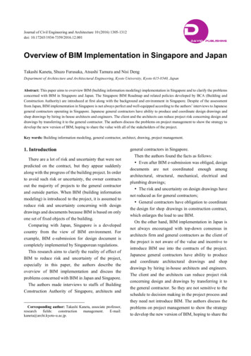
1.1 IntroductionIntegrated Building Performance Analysis (IBPA) can be a powerful tool to evaluate and inform decisionsthroughout the design process, starting at the earliest stages. In order to design a high-performance building andimplement an integrated process, the traditional design process needs to change. No longer can the design teamleave the analysis too late in design development, it needs to start early. By working holistically from conceptstage, the project team can analyse a number of options and make informed decisions on the associated pros andcons.The Virtual Environment (VE-Pro) is an integrated analysis platform developed by Integrated EnvironmentalSolutions (IES). It is a collection of building performance modelling and analysis modules leveraging a singleintegrated data model. The intent is to provide the high quality information required to design, build and operatebetter performing, more sustainable buildings without having to build a different model for each type of analysis(e.g. energy, daylighting, etc.). The VE is linked to Revit Architecture and Revit MEP through plug-ins that allowusers to build models in Revit and then analyse them using a range of products with the Virtual Environmentfamily. Integration with other BIM tools is achieved by importing data in a gbXML format into the VirtualEnvironment. The analysis tools include annual energy/carbon consumption, building loads, daylighting and electriclighting, climate, water, air flow and LEED/BREEAM/Greenstar credits. The Virtual Environment can be appliedfrom the earliest stages of the design process, when greatest opportunity often exists for making improvements,right through to detailed design and even into operation of the building.A key issue to understand is that there are fundamental differences between an energy model and an architecturalmodel used to generate construction documents and the ability to cycle through design options in a timely mannerrequires understanding of both. From the Engineers perspective they require only information pertinent to thequestion at hand, reducing variables will reduce analysis time. From the Architects perspective, the visualcharacter of the overall model is important to convey the design intent as well as the detail to express the layeringof ideas. gbXML (refer to section 1.4 - Basic gbXML information) is used to streamline the data flow from Revit toIES Virtual Environment. It is important to note that no exchange format is perfect and there are still limitations onwhat can be transferred between BIM and energy simulation software. An important point to note is that, manyBIM elements do not support information exchange identifying the thermal performance characteristics that areneeded to run energy analysis. Therefore, the users are required to specify these values at the point of translation,so the analysis can be performed with the appropriate characteristics. Architects tend to want to analyse their‘specific’ wall design with specific layers’, when, at an early stage, identifying the wall as an R-24 (thermal value)may be sufficient to develop comparative analysis between cases. When carrying out design exploration atdifferent stages of the process, it is advisable to utilise the appropriate level of detail for the analysis, making iteasier to focus on outputs that can inform the design. Too much detail at the early stages can cloud thefundamental design decisions.In order to take advantage of the ability to integrate BIM Building Performance Analysis, the BIM model needs tobe developed with this work flow considered. The usefulness and accuracy of the analysis results depend greatlyon the quality of the input data. The intent of this white paper is to provide guidance on best practice whencreating BIM models in order to successfully export to the VE for Building Performance Analysis and to leverage theability to do analysis cycles informing the design and testing ideas as the design evolves. This paper focusses on theRevit integration, however the principles are the same regardless of which BIM tool is being implemented.BIM Building Performance Analysis Using Revit 2014 and IES Virtual Environment2
1.2Basic gbXML InformationGreen Building XML schema, referred to as “gbXML”, was developed to facilitate the transfer of information frombuilding information models to performance (predominantly energy) analysis tools.When the user clicks on ‘Set Model Properties’ within Revit using the IES toolbar, in the background a gbXML fileis being read and exported. The 3D model the user sees is a gbXML model. This shows what will be exported foranalysis, so it’s important to look at this model to see what elements will translate correctly and what won’t.XML is a web-based, standards-compliant specification that can be used to store and transport virtually any kindof data. It is based on a relatively simple text-based syntax similar to HTML. Green Buildings XML (gbXML) wasdeveloped to facilitate interoperability between myriad building design and development modelling tools. IES isinvolved in development of the gbXML schema to enhance the translation and have included a number offeatures in the import function to smooth the gbXML import process.(Refer to www.gbxml.org for more detail information regarding gbXML documentation.)In order to facilitate a smooth translation from 3D modelling software (e.g. Revit) to the Virtual Environment thereare a number of considerations users should be aware of when creating their BIM (Revit) model.Like any type of analysis, the usefulness and accuracy of the results depend greatly on the quality of the inputs. Inorder to take advantage of this advanced workflow between the platforms, the Revit model must be properlyprepared for analysis. Under normal circumstances there will be a Revit model for documentation and a separate,stripped down version of the Revit model for export to the VE.All bounding elements from the model, i.e. the walls that make up a room, its floor and ceiling, (See section 1.12Surfaces) will translate as 2D surfaces which represents ‘enclosed’ geometry i.e. the 3D zone. (Rooms or spacesdepending on what version of Revit is being used).BIM Building Performance Analysis Using Revit 2014 and IES Virtual Environment3
1.3 Data Exchange gbXMLA gbXML document organizes information according to the following hierarchy: Location, Building, Space, Surfaceand Opening.Figure 1: gbXML structure1.4 AdjacenciesIn order for the building performance model to understand whether a surface is exterior or interior, placingRooms (refer to Section 1.9 - Rooms) accurately is critical. If there is no Room adjacent to another space, then thevertical wall is considered as an Exterior wall and the associated construction profile will be assigned. If Rooms areplaced on both sides of walls, then it is considered as Interior. Even if the space is a shaft or an unoccupied space,where a room might not typically be placed, it is important in this case that a Room is inserted otherwise therooms surrounding the shaft or unoccupied space will be read as exterior spaces. Refer to the diagrams belowwhich illustrate how gbXML determines surfaces. (Figures 2 – Adjacency Diagrams)Figure 2: Adjacency DiagramsBIM Building Performance Analysis Using Revit 2014 and IES Virtual Environment4
1.5Checklist for Translating Revit to IESVEThe following checklists/tips summarise the process users should go through in the Revit model beforeattempting to export the VE. . Each item is described in more detail in subsequent pages of this document.1.Rooms (refer to Section 1.9 - Rooms)Make sure all rooms/spaces are place in every area of the building to create a fully enclosed buildingenvelope, and adjacencies of Rooms are correct.2.Room Bounding Elements (refer to Section 1.12)Check or uncheck room bounding elements that are necessary for design / building Performancemodel. If an interior space has many ½ walls or jogs (that protrude into but do not divide spaces),these walls can often be made non-room bounding leaving a simple room perimeter to bound thespace.3. Define all Upper and Lower Boundary (refer to Section 1.14 - Defining the Upper & Lower Boundary)Make sure all the Upper and Lower Limits and Offsets are correct4.Project Information (refer to Section 1.8 - Project Information)Make sure the Energy Data parameter in the Project Information is filled out correctly5.Room Volume Computations (refer to Section 1.15 - Room Volume Computations)Make sure Room Volume Computations is checked6.If it’s a central model, detach from central.Clean up views, elements that are not related to energy analysis (casework, railings, etc.), andpurge unused. This will help reduce the size of the file.7.Try to keep the model as lean as possible in Revit,This will be worth it when trying to run analysis and will impact runtime greatly. Only keepelements essential to the gbXML. It is common to maintain separate Revit construction documentmodels and Revit analysis models, though in the future hopefully that will change. For analysis,simplicity of the model is paramount. For example, use a single wall from ground floor level to theroof instead of stacked or layered complex wall. Use actual window families instead of a curtainwall embedded in opaque walls. Use simple, generic families if possible. Always use the appropriatefamily type for any custom components.BIM Building Performance Analysis Using Revit 2014 and IES Virtual Environment5
1.6 Work Flow Example Revit to IESVirtual EnvironmentThis diagram illustrates a typical work flow using Revit.1. Design2. Translate3. Analyse4. Carry furtherFigure 3: Typical Workflow DiagramBIM Building Performance Analysis Using Revit 2014 and IES Virtual Environment6
1.7 Area & Volume ComputationThis has to be set to ‘Areas and Volumes’ for the successful creation of a gbXML file. (See section 1.15 - how to setthis)Figure 4: Area and Volume Computations1.7.1 LevelsIn addition a room or a space has to be placed everywhere in the model to create a fully enclosed buildingenvelope. These rooms/spaces (see section 1.9 Rooms and Spaces) should be tied to the levels within the model.This is best practice in the event that there are later updates to the floor levels which will in turn adjust theroom/space heights automatically if they are tied.Figure 5: Section through Revit ModelAt this stage the ‘Visibility Graphics’ can be turned on to check if the room or space placed is filling the model asrequired.Figure 6: Visibility Graphics Dialogue within RevitBIM Building Performance Analysis Using Revit 2014 and IES Virtual Environment7
1.8 Project InformationDefining the location of the project is very important for design / energy performance analysis because thisdetermines what weather data is used for the analysis. Location and associated climate play an important role inthe performance of the building and should be used to inform the design. This information can be set in Revit or inthe Virtual Environment plug-in.In Revit go to Manage LocationFigure 6: Setting Project Location in RevitThis can also be set within the ‘Energy Analysis’ Instance within the ‘Project Information’. (Figure 7- ProjectInformation Energy Analysis Energy Settings) In addition to the buildings location there is additional informationthat can be exported with the gbXML from Revit for building performance analysis. This information can also be setin the VE plugin. Details of this information are given below.Figure 7: Project Information - Project PropertiesBIM Building Performance Analysis Using Revit 2014 and IES Virtual Environment8
NB: There are a few differences between the Architecture & MEP settings (Figures 9/10 onthe following page), but the basic information is the same. In addition, there are othermethods to set project information. Location can be set on its own in the Manage Location.The same information as shown above can also be set in the Analyze Energy Settings or onexport when it is a manual gbXML export using the Revit gbXML function. When using the Virtual Environment Plugin, this information will be extracted automatically.Building Type:Specifies the type of building according to the gbXML schema 0.37("http://www.gbxml.org/schema" version "0.37") and Building Type spaces similar to ASHRAE Standard 90.1building categories.Postal Code: Location and climate should be set correctly as this will affect analysis results. Postal Code canbe used to determine the location of the building.Ground Plane: Specifies the level that serves as the ground level reference for the building. Spaces belowthis level are considered below ground. The default ground level in the Virtual Environment is zero.Project Phase: Specifies the stage of construction (Existing, New Construction). Make sure the Rooms thatare being placed in the Revit model are in the same phase as the Project Information. If the phase selectedin this dialog is different than the room property specified the user will see the warning dialogue shown inFigure 8 below.Figure 8: Project Information - Project Phase - Error DialogSliver Space Tolerance:Specifies the tolerance between surfaces within the model. Within the VirtualEnvironment this is referred to as the adjacency separation distance. Best practice is to leave the default that isdefined within the Revit dialog box. If the default is increased this could result in larger ‘sliver spaces’ which mayallow light, solar radiation, air flow and thermal transfer between zones that in reality do not exist.BIM Building Performance Analysis Using Revit 2014 and IES Virtual Environment9
Figure 9: Energy Settings - Revit Architecture 2014Figure 10: Energy Settings - Revit MEP 20141.8.1 Export Settings – Architecture v MEPBIM Building Performance Analysis Using Revit 2014 and IES Virtual Environment10
Export Complexity: To set this go to the Settings & Info Setting and select the gbXML Export tab. The user canselect from five different options ranging between Simple to Complex with Mullions and Shading Surfaces. Anexplanation of the 5 options is given below. The main advantage of this setting is that export time is reduced whenusing the simple options.Figure 11: VE plugin Settings & InfoFigure 12: VE plugin gbXML Export TabNB: There is one key difference between Revit MEP and Architecture in the ‘User Settings’ Dialogue. MEP has anoverride transfer option which allows the user to export settings for rooms such as lighting loads and occupancyinformation which have been set up within Revit.Figure 13: MEP Space Data – Space PropertiesThere are five levels of complexity for export, seeFigure 14 – gbXML Complexity:BIM Building Performance Analysis Using Revit 2014 and IES Virtual Environment11
1. Simple: Simple means that curtain walls and curtain systems are exported with one “large” opening withthe total opening area equal to all openings; a curtain wall with 50 panels gets exported as 1 opening. This isappropriate for thermal simulation, particularly early stage analysis.2. Simple with Shading Surfaces: Export with simple glazing type and shading surfaces3. Complex: Complex means that curtain walls and curtain systems are exported with several openings, panelby panel; a curtain wall with 50 panels will be exported as 50 openings4. Complex with Shading Surfaces: This will export with a complex glazing type and include shading surfaces5. Complex with Mullions and Shading Surfaces: This export option is the most complex type, includingshading surfaces and mullions. ‘With mullions’ means that mullions in curtain walls and systems are exportedas shading surfaces. A “simplified” analytical shading surface is produce from a mullion based on itscentreline, thickness and offset. Remember that this is the most complex type of export, and will createhundreds, even thousands of shading surfaces. Use the level necessary for the analysis required. This isappropriate for Radiance calculations where the user will want to see the effect of the mullions.Figure 14: gbXML ComplexityBIM Building Performance Analysis Using Revit 2014 and IES Virtual Environment12
1.9 Rooms & SpacesRooms are the most fundamental element for design/building performance analysis. They are elements thatdetermine the accuracy of analysis from a Revit model. There are two different ways to model these within Revitwhich is determined by what Autodesk product the user is running.Revit Architecture 2014Revit MEP 2014In Revit Architecture the user defines ROOMS in the model which the gbXML will recognise on export. In RevitMEP the user defines SPACES and can do so using an automatic SPACE placement tool. If these are not set thecorrect way round there is a warning that will pop up. (P10: Figure 8 - Project Information - Project Phase - ErrorDialog)If this does occur then the user can define within Revit weather to export Rooms or Spaces. To alter this go to theenergy settings in the project information (P9 Section 1.8 Project Information) or go to File Export gbXML andopen up the ‘Export gbXML’ settings dialogue. In the ‘Export Category either can be defined for export.Figure 15: Export gbXML Settings – RevitNOTE: Within the gbXML schema the Space is the analogy for a Room. For the purposes of clarity in this paper wewill refer to these elements as Rooms in all cases.BIM Building Performance Analysis Using Revit 2014 and IES Virtual Environment13
“Room inside a Room”The VE does translate the “room inside a room” or “donut” condition shown below, (Figure 16: Room inside aRoom condition) but a cleaner geometry can be achieved by modelling the outer room as two parts utilising roomseparation lines.Figure 16: Room inside a Room conditionWhere do we see this condition?Elevator ShaftsChasesClosetsCore and Shell style buildingsAVOID floor openings. Add these in VE if necessaryAnother issue to consider when creating the Revit model are the two different ways to model and define roomswithin the Revit model; one is Zone-Based Modelling and the other is Room-Based Modelling.BIM Building Performance Analysis Using Revit 2014 and IES Virtual Environment14
1.9.1 Zone-Based ModellingZone-Based modeling is the concept of modeling and defining the Room by the thermal zone. A thermal zone is anindividual space or group of interior spaces with the same thermal conditioning requirements.Zone-Based modeling is especially useful when the project is in early design stage, since the internal layout mightnot be certain, it is best to simplify elements as much as possible.The best way to defined Zone-Based modeling is to group all Rooms with similar thermal and space characteristicssuch as solar orientation, occupancy, lighting, and equipment loads into one Room. For example, in an officebuilding, perimeter offices that are facing a similar orientation could be combined into one ‘Room’ (Figure 18:Zone-Based Modeling - Floor Plan).When choosing any of these options the key is to carefully consider what outputs are required from the analysis.Figure 17: Zone-Based Modeling - Floor Plan - Perimeter vs CoreFigure 18: Zone-Based Modeling - Floor PlanBIM Building Performance Analysis Using Revit 2014 and IES Virtual Environment15
1.9.2 Room-Based ModellingRoom-Based Modeling is the concept of modeling and defining each Room as its own thermal zone. There arecases where this might occur, for example, a hotel, even though the hotel suites might be all facing similarorientation, but since each room can be thermal controlled separately, it might be useful to use Room-BasedModeling method rather than Zone-Based modeling.For Room-Based Modeling, or any thermal modelling, it is important to place a “Room” in every space of themodel, even if the space volume is a shaft.For example in Figure 20, the two rooms highlighted in red could beoverlooked because the user does not want to analyse the results of these rooms. However in order for the modelto be translated correctly these must be defined as rooms otherwise the model will come through with holes andinternal surfaces represented as external in the geometry which will affect the results. The end goal is to achieve afully enclosed building enevelope.Figure 19: Room-Based Modeling - Floor PlanFigure 20: Placing RoomsBIM Building Performance Analysis Using Revit 2014 and IES Virtual Environment16
1.10 Shading SurfacesWhen surface are created that are not room bounding these are interpreted as shading elements in the VirtualEnvironment when Room bounding elements are not bound by a Room. Roof Overhangs, balconies, or evensurrounding buildings can be defined in this way and should all be considered when running building analysisbecause they will shade the building; however they should not be considered as rooms for analysis.Shading devices need to be created as an obstruction with wall, roof or mullion families (Figure 22 - Curtain WallMullions Translation). The massing tool can also be used to build shading and then apply walls, floors and roofs byface.Floor families and in-place systems will not translate as shading.NOTE: Within the Virtual Environment, Shading surfaces, shading devices, surround buildings are known asobstructions. For the purpose of clarity here, these items are referred to as shading surfaces throughout.Figure 21: Shading Surfaces TranslationFigure 22: Curtain Wall Mullions TranslationBIM Building Performance Analysis Using Revit 2014 and IES Virtual Environment17
1.11 Rooms vs Shading SurfacesThe best way to check if the elements are translating as Rooms or Shading Surfaces is to go to IES Set ModelProperties dialog (Figure 23 - IES Set Model Properties). Elements that are in blue will be treated as Rooms (Figure24 - Set Model Properties - Model Translation - Room), and elements that are in yellow will be treated as ShadingSurfaces (Figure 25 - IES Set Model Properties - Model Translation - Room with Shading Surfaces)Figure 23: IES Set Model PropertiesFigure 24: Set Model Properties - Model Translation – RoomFigure 25: Set Model Properties - Model Translation - Room with Shading SurfacesBIM Building Performance Analysis Using Revit 2014 and IES Virtual Environment18
1.12 SurfacesRooms are defined by bound volumes for gbXML translation from a Revit model to a building performance model.During the translation of the Revit model, these bounding elements are translated into 2D surfaces that enclosethe 3D spaces (rooms). (See Figure 26 - Revit Model Translation to Virtual Environment)The following elements are room bounding elements for Room Area a
Revit integration, however the principles are the same regardless of which BIM tool is being implemented. BIM Building Performance Analysis Using Revit 2014 and IES Virtual Environment 3 1.2 Basic gbXML Information Green uilding XML schema, referred to as “gbXML”, was dev