Transcription
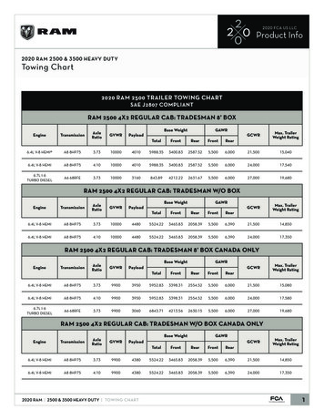
Instruction Manual2500 and 2503 Controllers/TransmittersD200124X012June 2022Fisher 2500 and 2503 Controllers and TransmittersContentsIntroduction . . . . . . . . . . . . . . . . . . . . . . . . . . . . . . . . . 2Scope of Manual . . . . . . . . . . . . . . . . . . . . . . . . . . . . . 2Description . . . . . . . . . . . . . . . . . . . . . . . . . . . . . . . . . 2Specifications . . . . . . . . . . . . . . . . . . . . . . . . . . . . . . . 2Educational Services . . . . . . . . . . . . . . . . . . . . . . . . . 2Installation . . . . . . . . . . . . . . . . . . . . . . . . . . . . . . . . . . . . 5Sensor Assembly . . . . . . . . . . . . . . . . . . . . . . . . . . . . 6Uncrating . . . . . . . . . . . . . . . . . . . . . . . . . . . . . . . . . . 6Controller/Transmitter Orientation . . . . . . . . . . . . . 7Mounting Caged Sensor . . . . . . . . . . . . . . . . . . . . . . 8Mounting Cageless Sensor . . . . . . . . . . . . . . . . . . . 10Side‐Mounted Sensor . . . . . . . . . . . . . . . . . . . . 10Top‐Mounted Sensor . . . . . . . . . . . . . . . . . . . . 12Supply and Output Pressure Connection . . . . . . . . 12Supply Pressure . . . . . . . . . . . . . . . . . . . . . . . . . 12Controller/Transmitter Output Connection . . 13Vent Assembly . . . . . . . . . . . . . . . . . . . . . . . . . . . . . 13Prestartup Checks . . . . . . . . . . . . . . . . . . . . . . . . . . . 142500 Controller or 2500T Transmitter . . . . . . . . . . 172500S Controller . . . . . . . . . . . . . . . . . . . . . . . . . . . 182503 Controller . . . . . . . . . . . . . . . . . . . . . . . . . . . . 18Adjustments . . . . . . . . . . . . . . . . . . . . . . . . . . . . . . . 19Control Action . . . . . . . . . . . . . . . . . . . . . . . . . . 19Level Adjustment (Controllers Only) . . . . . . . . 19Zero Adjustment (Transmitters Only) . . . . . . . 20Proportional Band Adjustment(Except Transmitters and 2503Controllers) . . . . . . . . . . . . . . . . . . . . . . . . . . 20Specific Gravity Adjustment(Transmitters Only) . . . . . . . . . . . . . . . . . . . 20Calibration . . . . . . . . . . . . . . . . . . . . . . . . . . . . . . . . . . . 20Precalibration Requirements . . . . . . . . . . . . . . . . . 20Wet Calibration . . . . . . . . . . . . . . . . . . . . . . . . . 20Dry Calibration . . . . . . . . . . . . . . . . . . . . . . . . . 21Controller/Transmitter and Torque Tube ArmDisassembly . . . . . . . . . . . . . . . . . . . . . . . . . 21Determining the Amount ofSuspended Weight . . . . . . . . . . . . . . . . . . . . 21Calibration Procedure . . . . . . . . . . . . . . . . . . . . . . . 222500 Controller and 2500T Transmitter . . . . . 232500S and 2503 Controllers . . . . . . . . . . . . . . 25Startup . . . . . . . . . . . . . . . . . . . . . . . . . . . . . . . . . . . . . . 272500 Controller . . . . . . . . . . . . . . . . . . . . . . . . . . . . 272500T Transmitter . . . . . . . . . . . . . . . . . . . . . . . . . . 272500S Controller . . . . . . . . . . . . . . . . . . . . . . . . . . . 272503 Controller . . . . . . . . . . . . . . . . . . . . . . . . . . . . 27www.Fisher.comFigure 1. Fisher 2500 or 2503 Controller/Transmitteron 249 Caged Sensor2500 OR 2503CONTROLLER/TRANSMITTER249 SENSORW8334Principle of Operation . . . . . . . . . . . . . . . . . . . . . . . .2500 Controller or 2500T Transmitter . . . . . . . . . .Proportional Valve . . . . . . . . . . . . . . . . . . . . . . . . . .2500S Controller . . . . . . . . . . . . . . . . . . . . . . . . . . .2503 Controller . . . . . . . . . . . . . . . . . . . . . . . . . . . .Maintenance . . . . . . . . . . . . . . . . . . . . . . . . . . . . . . . .Troubleshooting . . . . . . . . . . . . . . . . . . . . . . . . . . . .Removing Controller/Transmitter from Sensor . .Changing Mounting Methods . . . . . . . . . . . . . . . . .Installing Controller/Transmitter on Sensor . . . . .Replacing the Bourdon Tube . . . . . . . . . . . . . . . . . .Changing Action . . . . . . . . . . . . . . . . . . . . . . . . . . . .Relay Deadband Testing (2500 Controlleror 2500T Transmitter Only) . . . . . . . . . . . . . . . .Replacing the Proportional Valve . . . . . . . . . . . . . .Changing Relay . . . . . . . . . . . . . . . . . . . . . . . . . . . . .Parts Ordering . . . . . . . . . . . . . . . . . . . . . . . . . . . . . . .Parts List . . . . . . . . . . . . . . . . . . . . . . . . . . . . . . . . . . .2728282829303132333435353637373738
2500 and 2503 Controllers/TransmittersInstruction ManualD200124X012June 2022IntroductionScope of ManualThis manual provides installation, operating, calibration, maintenance, and parts ordering information for 2500 and2503 pneumatic controllers and transmitters used in combination with 249 displacer sensors.NoteThis manual does not include installation or maintenance procedures for the supply pressure regulator, sensor, or other devices.For that information, refer to the appropriate instruction manual for the other device.Do not install, operate, or maintain a 2500 or 2503 pneumatic controller/transmitter without being fullytrained and qualified in valve, actuator, and accessory installation, operation, and maintenance. To avoidpersonal injury or property damage, it is important to carefully read, understand, and follow all contentsof this quick start guide, including all safety cautions and warnings. If you have any questions aboutthese instructions, contact your Emerson sales office before proceeding.DescriptionThese instruments control or transmit the fluid level, the level of interface between two fluids, or the density (specificgravity). Each unit consists of a 249 displacer‐type fluid level sensor and a 2500 or 2503 pneumatic controller ortransmitter. Figure 1 shows a typical controller‐sensor combination.SpecificationsRefer to table 1 for specifications.Educational ServicesEmerson Automation SolutionsEducational Services - RegistrationPhone: 1-800-338-8158E-mail: education@emerson.comemerson.com/mytraining2
Instruction Manual2500 and 2503 Controllers/TransmittersD200124X012June 2022Table 1. SpecificationsAvailable Configurations(1)Per ISO 8573-1Maximum particle density size: Class 7Oil content: Class 3Pressure Dew Point: Class 3 or at least 10 C less thanthe lowest ambient temperature expectedFisher 2500 Series controllers and transmittersinclude the following models:2500—Proportional‐only controller2500C—Proportional‐only controller with indicator(see figure 10)2500R—Reverse acting proportional‐only controller2500S—Differential gap (snap acting) controller. Seechanging controller action procedure and figure 152500T—Transmitter2503—Differential gap controller withoutproportional valve; for applications requiring verylittle adjustmentMaximum Supply Pressure(2,3)3 bar (45 psig) to the controller or transmitter. Ifcontroller or transmitter is equipped with anintegrally mounted 67CFR filter/regulator, typicalsupply pressure to the regulator is from 2.5 bar (35psig) to 17 bar (250 psig), maximum. For supplypressures to the filter/regulator, refer to theappropriate regulator instruction manual.Input SignalFluid Level or Fluid‐to‐Fluid Interface Level: From 0 to100% of displacer length—standard lengths for allsensors are 356 mm or 812 mm(14 inches or 32 inches). Other lengths availabledepending on sensor construction.Steady‐State Air Consumption2500 Controllers and Transmitters (2500, 2500C,2500R, 2500S, and 2500T): See table 32503 Controller: Vents only when relay is exhaustingFluid Density: From 0 to 100% of displacement forcechange obtained with given displacer volume.Standard volume for displacers are listed in table 2.Proportional Band Adjustment (Proportional‐OnlyControllers)Output SignalFull output pressure change adjustable over 10 to100% of displacer length(4)2500 Controller and 2500T Transmitter: 0.2 to 1 bar(3 to 15 psig) or 0.4 to 2 bar (6 to 30 psig)Differential Gap Adjustment (Differential GapControllers)2500S and 2503 Differential Gap Controllers: 0 bar (0psig) when switched off and full supply [1.4 or 2.4 bar(20 or 35 psig) nominal depending on controlleroutput pressure range] when switched on.2500S Controller: Full output pressure changeadjustable from 20 to 100% of displacer length.(4)2503 Controller: Full output pressure changeadjustable over approximately 25 to 40% of displacerlength(4)Area Ratio of Relay Diaphragms3:1Supply Pressure DataSpan Adjustment (2500T Transmitter)See table 3(2)Full output pressure change adjustable from 20 to100% of displacer length(4)Supply MediumAir or Natural GasSet Point (controllers only) or Zero (transmittersonly) AdjustmentSupply medium must be clean, dry, and noncorrosivePer ISA Standard 7.0.01A maximum 40 micrometer particle size in the airsystem is acceptable. Further filtration down to 5micrometer particle size is recommended. Lubricantcontent is not to exceed 1 ppm weight (w/w) orvolume (v/v) basis. Condensation in the air supplyshould be minimizedFor proportional‐only controllers or transmitters,level adjustment positions the set point or zero forthe fluid level, interface level, or displacer forcechange (density) within the displacer length.For differential gap controllers, level adjustmentsimultaneously positions both ends of the gap withinthe displacer length.(continued)3
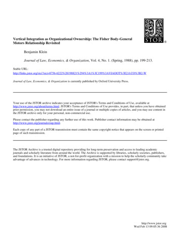
Instruction Manual2500 and 2503 Controllers/TransmittersD200124X012June 2022Table 1. Specifications (Continued)PerformanceTypical Ambient Temperature Operating InfluenceOutput pressure changes 1.5% per 10 C (50 F)change in temperature at 100% proportional bandwhen using a standard wall torque tube with 249sensorsIndependent Linearity (transmitters only): 1% ofoutput pressure change for 100% span.Hysteresis: 0.6% of output pressure change at 100%proportional band, differential gap, or spanHazardous Area ClassificationRepeatability: 0.2% of displacer length ordisplacement force change2500 and 2503 controllers/transmitters comply withthe requirements of ATEX Group II Category 2 Gasand DustDeadband (except differential gap controllers(5)):0.05% of proportional band or spanEx h IIC Tx GbEx h IIIC Tx DbTypical Frequency Response: 4 Hz and 90 degreephase shift at 100% proportional band with outputpiped to typical instrument bellows using 6.1 meters(20 feet) of 1/4‐inch tubingMaximum surface temperature (Tx) depends onoperating conditionsGas: T4, T5, T6Dust: T85.T104Ambient Operating Temperature Limits(3)For ambient temperature ranges and guidelines foruse of the optional heat insulator assembly, see figure2. Relay temperature limits are:Standard Construction: ‐40 to 71 C (‐40 to 160 F)High‐Temperature Construction: ‐18 to 104 C(0 to 220 F)Supply and Output Connections1/4 NPT internalMaximum Working Pressure (sensors only)Refer to the appropriate sensor instruction manualNOTE: Specialized instrument terms are defined in ANSI/ISA Standard 51.1 - Process Instrument Terminology.1. Controllers are field adjustable between direct or reverse action. The letter R in the type number indicates that the controller/transmitter shipped from the factory set for reverse action (see chang ing controller action procedures). The letter C in the type number indicates that a pointer is attached to the torque tube shaft providing visual monitoring of torque tube motion.2. Control and stability may be impaired if the maximum pressures are exceeded.3. The pressure/temperature limits in this document, and any applicable standard or code limitation should not be exceeded.4. These statements apply only to units sized to produce a full output change for a 100% level change at the maximum proportional band dial setting.5. Adjusting the span of the differential gap controller is equivalent to adjusting the deadband.Table 2. Standard Displacer VolumesSensorStandard VolumeLitersStandard VolumeCubic Inches1.61.01.91.3(3)100(1) 60(2)120 80(3)249, 249B, 249BF, 249BP, 249K, 249P, 249W249C, 249CP, 249W249L249VS1. For 249W, with standard 812 mm (32‐inch) displacer.2. For 249W, with standard 356 mm (14‐inch) displacer.3. With standard 305 mm (12‐inch) flange‐face‐to‐displacer centerline dimension only.Table 3. Supply Pressure DataOUTPUT SIGNAL RANGESTANDARD SUPPLY ANDOUTPUTPRESSURE GAUGEINDICATIONS(1)0.2 to 1 bar (3 to 15 psig)0 to 30 psig0.4 to 2 bar (6 to 30 psig)1.2.3.4.5.40 to 60 psigNORMAL OPERATINGSUPPLY PRESSURE(2)AIR CONSUMPTION ATNORMAL OPERATINGSUPPLY PRESSUREMinimum(3)Maximum(4)MAXIMUMSUPPLY PRESSUREBarPsig1.4204.2 scfh(5)27 scfh(5)3 bar (45 psig)357 scfh(5)42 scfh(5)3 bar (45 psig)2.4Consult your Emerson sales office about gauges in other units.Control and stability may be impaired if this pressure is exceeded.At zero or maximum proportional band or specific gravity setting.At setting in middle of proportional band or specific gravity range.If air consumption is desired in normal m3/hr at 0 C and 1.01325 bar, multiply scfh by 0.0258.
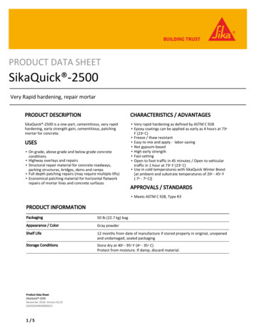
Instruction Manual2500 and 2503 Controllers/TransmittersD200124X012June 2022Figure 2. Guidelines for Use of Optional Heat Insulator AssemblyAMBIENT TEMPERATURE ( C)102030405060 18 101100593800TOOHOTHEAT INSULATORREQUIRED0 18NO INSULATOR NECESSARY 20 29USE INSULATOR (CAUTION! IF AMBIENT DEWPOINT IS ABOVEPROCESS TEMPERATURE, ICE FORMATION MAY CAUSE INSTRUMENTMALFUNCTION AND REDUCE INSULATOR EFFECTIVENESS.)0204060500400300200100400 40717080100120140 40010AMBIENT TEMPERATURE ( C)20304050607080100 10590HEAT INSULATORREQUIRED800593500TOOHOT400300200400100NO INSULATOR NECESSARY00USE INSULATOR (CAUTION! IF AMBIENT DEWPOINT IS ABOVE PROCESSTEMPERATURE, ICE FORMATION MAY CAUSE INSTRUMENT MALFUNCTION ANDREDUCE INSULATOR EFFECTIVENESS.)PROCESS TEMPERATURE ( C)0PROCESS TEMPERATURE ( C)PROCESS TEMPERATURE ( F) 10PROCESS TEMPERATURE ( F) 181100 201600AMBIENT TEMPERATURE ( F)20406080100120140160180200220AMBIENT TEMPERATURE ( F)STANDARD CONTROLLER OR TRANSMITTERHIGH‐TEMPERATURE CONTROLLER OR TRANSMITTERNOTE:FOR APPLICATIONS BELOW -29 C (-20 F), BE SURE THE SENSOR MATERIALS OF CONSTRUCTIONARE APPROPRIATE FOR THE SERVICE TEMPERATURE.CV6190-EB1413‐3Table 4. Displacer and Torque Tube MaterialsPartStandard MaterialOther MaterialsDisplacer304 Stainless Steel316 Stainless Steel, N10276, N04400, Plastic, and Special AlloysDisplacer Stem, Driver Bearing,Displacer Rod and Driver316 Stainless SteelN10276, N04400, other Austenitic Stainless Steels, and Special AlloysTorque TubeN05500(1)316 Stainless Steel, N06600, N102761. N05500 is not recommended for spring applications above 232 C (450 F). Contact your Emerson sales office or application engineer if temperatures exceeding this limit are required.Installation2500 and 2503 controller/transmitters work in combination with 249 displacer‐type sensors. The factory attaches thecontroller/transmitter to the sensor, unless it is ordered separately.If using natural gas as the pneumatic supply medium, natural gas will be used in the pressure connections of the unitto any connected equipment. The unit will vent natural gas into the surrounding atmosphere.WARNINGAlways wear protective clothing, gloves, and eyewear when performing any installation operations to avoid personalinjury.Check with your process or safety engineer for any additional measures that must be taken to protect against processmedia.If installing into an existing application, also refer to the WARNING at the beginning of the Maintenance section in thisinstruction manual.NOTICEDo not use sealing tape on pneumatic connections. This instrument contains small passages that may become obstructedby detached sealing tape. Thread sealant paste should be used to seal and lubricate pneumatic threaded connections.5
2500 and 2503 Controllers/TransmittersJune 2022Instruction ManualD200124X012WARNINGPersonal injury or property damage may result from fire or explosion if natural gas is used as the supply medium andpreventive measures are not taken. Preventive measures may include, but are not limited to, one or more of the following:Remote venting of the unit, re‐evaluating the hazardous area classification, ensuring adequate ventilation, and theremoval of any ignition sources. For information on remote venting of this controller refer to page 13.Sensor AssemblyTable 2 lists sensors recommended for use with controller/transmitters. Table 4 contains displacer and torque tubematerials. For sensor installation and maintenance, refer to the appropriate sensor instruction manual.WARNINGWhen replacing the sensor assembly, the displacer may retain process fluid or pressure. Personal injury or propertydamage may occur due to sudden release of the pressure. Contact with hazardous fluid, fire, or explosion can be caused bypuncturing, heating, or repairing a displacer retaining process pressure or fluid. This danger may not be readily apparentwhen disassembling the sensor assembly or removing the displacer. Before disassembling the sensor or removing thedisplacer, observe the more specific warning provided in the sensor instruction manual.UncratingUnless ordered separately, the controller/transmitter is attached to the sensor when shipped. Carefully uncrate theassembly.NOTICESensors used for interface or density control may be so large and heavy that the torque tube cannot fully support theirweight in air. On the 249VS, a travel stop is used to prevent damage. Do not remove this travel stop assembly without firstremoving the displacer from the displacer rod. Refer to the appropriate instruction manual for 249 cageless sensors.NoteCaged sensors have rods and blocks installed at each end of the displacers to protect the displacers in shipping. Remove theseparts before you install the sensor to allow the displacer to function properly.Caged sensors come with the displacer installed in the cage. If a tubular gauge glass is ordered with the sensor, thegauge glass is crated separately and must be installed at the site. A damping plate is installed in the lower screwed orflanged connection (see figure 3) to provide more stable operation. Be certain that the cage equalizing connectionsand the damping plate are not plugged by foreign material.6
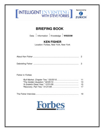
Instruction Manual2500 and 2503 Controllers/TransmittersD200124X012June 2022Figure 3. Damping Plate ING PLATEFLANGEDCONNECTIONW0144-1A cageless sensor comes with its displacer separated from the sensor assembly. Displacers longer than 813 mm (32inches) come in a separate crate. Shorter displacers come in the same crate as the sensor, but are not attached to theirdisplacer rods. Inspect the displacer to ensure it is not dented. A dent may reduce the pressure rating of the displacer.If a displacer is dented, replace it.Controller/Transmitter OrientationThe controller/transmitter attaches to the sensor in one of the mounting positions shown in figure 4. Right‐handmounting is with the controller or transmitter case to the right of the displacer when you look at the front of the case;left‐hand mounting is with the case to the left of the displacer. The mounting position can be changed in the field.Changing this mounting position changes the control action from direct to reverse, or vice versa.All caged sensors have a rotatable head. That is, the controller/transmitter may be positioned at any of eight alternatepositions around the cage as indicated by the numbers 1 through 8 in figure 4. To rotate the head, remove the headflange bolts and nuts and position the head as desired.7
2500 and 2503 Controllers/TransmittersInstruction ManualD200124X012June 2022Figure 4. Cage Head Mounting PositionsRIGHT‐HAND MOUNTINGLEFT‐HAND MOUNTING1 67CFR FILTER/REGULATOR.AH9150-AA2613-2Mounting Caged SensorNoteInstall the cage so that it is plumb; the displacer must not touch the cage wall. If the displacer touches the cage wall, the unit willtransmit an erroneous output signal.NoteIf the controller/transmitter is not mounted on the sensor, refer to the Installing Controller/Transmitter on Sensor procedures inthe Maintenance section. This section also provides instructions for adding a heat insulator to a unit.Cage connections normally are either NPS 1‐1/2 or 2, screwed or flanged. Figure 5 shows the combinations. Withflanged connections, use standard gaskets or other flat‐sheet gaskets compatible with the process fluid. Spiral‐woundgaskets without compression‐controlling centering rings cannot be used for flange connections.8
Instruction Manual2500 and 2503 Controllers/TransmittersD200124X012June 2022Figure 5. Cage Connection StylesSTYLE 1: TOPAND BOTTOMSCREWED: S1FLANGED: F1STYLE 2: TOPAND LOWER SIDESTYLE 3: UPPERAND LOWER SIDESCREWED: S2FLANGED: F2SCREWED: S3FLANGED: F3STYLE 4: UPPERSIDE AND BOTTOMSCREWED: S4FLANGED: F4A1271-2As shown in figure 6, mount the cage by running equalizing lines between the cage connections and the vessel. Ashutoff or hand valve with a 1‐1/2 inch diameter or larger port should be installed in each of the equalizing lines. Alsoinstall a drain between the cage and shutoff or hand valve whenever the bottom cage line has a fluid‐trapping lowpoint.Figure 6. Caged Sensor MountingEQUALIZING LINECENTER OF LIQUIDOR INTERFACE LEVELSHUTOFFVALVESDRAIN VALVEEQUALIZING LINEDF5379‐AA1883‐29
2500 and 2503 Controllers/TransmittersInstruction ManualJune 2022D200124X012On fluid or interface level applications, position the sensor so that the center line on the cage (see figure 6) is as closeas possible to the center of the fluid level or interface level range being measured. Also consider installing a gaugeglass on the vessel, or on the sensor cage (if the cage is tapped for a gauge).Mounting Cageless SensorNoteIf a stillwell is used, install it plumb so that the displacer does not touch the wall of the stillwell. If the displacer touches the wall,the unit will transmit an erroneous output signal.Since the displacer hangs inside the vessel, provide a stillwell around the displacer if the fluid is in a state of continuousagitation to avoid excessive turbulence around the displacer.NoteDisplacers used in an interface level application must be completely submerged during operation. If displacers aren't completelysubmerged, they will not calibrate or perform properly. To obtain the desired controller or transmitter sensitivity may requireusing either a thin‐wall torque tube, an oversized displacer, or both.NoteIf the controller/transmitter is not mounted on the sensor, refer to the Installing Controller/Transmitter on Sensor procedures inthe Maintenance section. This section also provides instructions for adding a heat insulator to a unit.Attach a cageless sensor to a flanged connection on the vessel as shown in figure 7. For interface or fluid levelapplications, install a gauge glass on the vessel.Side‐Mounted SensorIf a stillwell is required (see figure 7), attach the displacer to the displacer rod from inside the vessel.Connect the displacer as shown in figure 8, locking the assembly with the cotter spring provided. If a stillwell is notrequired, attach the displacer rod before mounting the sensor on the vessel. Then, you can swing the displacer outhorizontally for insertion into the vessel. However, once the sensor is installed and the displacer drops to a verticalposition, the displacer may not be capable of being withdrawn for servicing later. Be sure there is another access to thedisplacer to permit swinging it to a horizontal position or to permit disconnecting it from the displacer rod.If an extension is used between the displacer spud and the displacer stem end piece, make sure the nuts are tight ateach end of the displacer stem extension. Install and tighten suitable bolting or cap screws in the flanged connectionto complete the installation.10
Instruction Manual2500 and 2503 Controllers/TransmittersD200124X012June 2022Figure 7. Cageless Sensor MountingTOP MOUNTEDSIDE MOUNTEDW9517‐1SIDE VIEW (SHOWING STILLWELL)CF5380‐AA3893SIDE VIEW (WITHOUT STILLWELL)Figure 8. Displacer and Displacer Rod ConnectionsCOTTER SPRINGDISPLACER RODCOTTER SPRINGDISPLACERSPUDDISPLACERSTEM EXTENSIONLOCKING NUTSDISPLACER SPUDW0228‐1ADISPLACER RODALL OTHER TYPESW9357249VS11
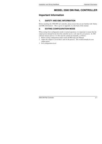
2500 and 2503 Controllers/TransmittersJune 2022Instruction ManualD200124X012Top‐Mounted SensorNOTICEIf inserting the displacer into the vessel before attaching to the displacer rod, provide a means of supporting the displacerto prevent it from dropping into the vessel and suffering damage.Figure 7 shows an example of a top‐mounted cageless sensor. You may attach the displacer to the displacer rod beforeinstalling the sensor on the vessel. If the displacer diameter is small enough, you may install a long or sectionalizeddisplacer through the sensor head access hole after the sensor is installed on the vessel. Connect the displacer asshown in figure 8, locking the assembly with the cotter springs provided. If a stem extension is used between thedisplacer spud and the stem end piece, make sure the nuts are tight at each end of the stem. Install and tightensuitable cap screws in the flanged connection to complete the installation.A special travel stop may be provided on top‐mounted sensors to aid in servicing of the sensor. This option preventsdropping the displacer and stem when the displacer rod is disconnected.Supply and Output Pressure ConnectionsWARNINGTo avoid personal injury or property damage resulting from the sudden release of pressure, do not install any systemcomponent where service conditions could exceed the limits given in this manual. Use pressure‐relieving devices asrequired by government or accepted industry codes and good engineering practices.NOTICEDo not use sealing tape on pneumatic connections. This instrument contains small passages that may become obstructedby detached sealing tape. Thread sealant paste should be used to seal and lubricate pneumatic threaded connections.Figure 9 shows dimensions, locations, and connections for controller/transmitter installation. All pressure connectionsto the controller/transmitter are 1/4 NPT internal.Supply PressureWARNINGPersonal injury or property damage may occur from an uncontrolled process if the supply medium is not clean, dry, oil‐freeair, or noncorrosive gas. While use and regular maintenance of a filter that removes particles larger than 40 micrometers indiameter will suffice in most applications, check with an Emerson Automation Solutions field office and industryinstrument air quality standards for use with corrosive air or if you are unsure about the proper amount or method of airfiltration or filter maintenance.Supply pressure medium must be clean, dry, and noncorrosive and meet the requirements of ISA Standard 7.0.01 orISO 8573-1. A maximum 40 micrometer particle size in the air system is acceptable. Further filtration down to 512
Instruction Manual2500 and 2503 Controllers/TransmittersD200124X012June 2022micrometer particle size is recommended. Lubricant content is not to exceed 1 ppm weight (w/w) or volume (v/v)basis. Condensation in the air supply should be minimized.Figure 9. Controller/Transmitter Dimensions and ConnectionsOPTIONAL 6.94)5/6‐18 UNC‐2B4 MOUNTING HOLESONj 95.3/3.75 DBC58.7(2.31)123.7(4.87)239.0(9.41)231.6(9.12)TOP VIEW1/4‐18 NPTOUTPUT CONN255.5(10.06)VENT1/4‐18 NPTOUTLET CONNPLUGGED67CFR1/4‐18 NPTSUPPLY CONNBACK VIEWFRONT VIEWAP4158‐DE0859mm(INCH)Use a suitable supply pressure regulator to reduce the supply pressure to the normal operating supply pressure shownin table 3. As shown in figure 9, a 67CFR filter/regulator mounts on the back of the controller/transmitter case andmates with the supply pressure connection on the controller/transmitter case. Pipe the supply pressure to the INconnection of the regulator. Typically, the 67CFR filter/regulator accepts supply pressures between 2.5 and 17 bar(35 and 250 psig). For specific regulator limits, refer to the appropriate regulator instruction manual.If operating the controller or transmitter from a high pressure source [up to 138 bar (2000 psig)], use a high pressureregulator system, such as the 1367 High Pressure Instrument Supply System. For 1367 system installation,adjustment, and maintenance information, see the separate instruction manual.Controller/Transmitter Output ConnectionAs shown in figure 9, the output pressure connection is on the back of the controller/transmitter case. Afterconnecting the output pressure line, turn on the supply pressure, adjust the filter/regulator to the appropriate supplypressure required for the controller/transmitter and check all connections for leaks.Vent AssemblyWARNINGPersonal injury or property damage could result from fire or explosion of accumulated gas, or from contact with hazardousgas, if a flammable or hazardous gas is used as the supply pressure medium. Because the instrument case and cover13
2500 and 2503 Controllers/TransmittersInstruction ManualJune 2022D200124X012assembly do not form a gas‐tight seal when the assembly is enclosed, a remote vent line, adequate ventilation, andnecessary safety measures should be used to prevent the accumulation of flammable or hazardous gas. However, a remotevent pipe alone cannot be relied upon to remove all flammable and hazardous gas. Vent line piping should comply withlocal and regional codes, and should be be as short as possible with adequate inside diameter and few bends to reduce casepressure buildup.NOTICEWhen installing a remote vent pipe, take care not to overtighten the pipe in the vent connection. Excessive torque willdamage the threads in the connection.The vent assembly (see figure 9) or the end of a remote vent pipe must be protected against the entrance of all foreignmatter that could plug the vent. Use 13 mm (1/2-inch) pipe for the remote vent pipe, if one is required. Check the ventperiodically to be certain it has not become plugged.Prestartup ChecksAdjustments are shown in figure 10 unless otherwise indicated. Open‐loop conditions must exist when performing theprestartup checks. To obtain open‐loop conditions:D make sure there
2500 Controller and 2500T Transmitter: 0.2 to 1 bar (3 to 15 psig) or 0.4 to 2 bar (6 to 30 psig) 2500S and 2503 Differential Gap Controllers: 0 bar (0 psig) when switched off and full supply [1.4 or 2.4 bar (20 or 35 psig) nominal depending on controller output pressure range] when switched on.