Transcription
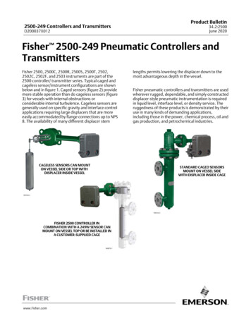
Product Bulletin2500-249 Controllers and Transmitters34.2:2500June 2020D200037X012Fisher 2500‐249 Pneumatic Controllers andTransmittersFisher 2500, 2500C, 2500R, 2500S, 2500T, 2502,2502C, 2502F, and 2503 instruments are part of the2500 controller/ transmitter series. Typical caged andcageless sensor/instrument configurations are shownbelow and in figure 1. Caged sensors (figure 2) providemore stable operation than do cageless sensors (figure3) for vessels with internal obstructions orconsiderable internal turbulence. Cageless sensors aregenerally used on specific gravity and interface controlapplications requiring large displacers that are moreeasily accommodated by flange connections up to NPS8. The availability of many different displacer stemlengths permits lowering the displacer down to themost advantageous depth in the vessel.Fisher pneumatic controllers and transmitters are usedwherever rugged, dependable, and simply constructeddisplacer‐style pneumatic instrumentation is requiredin liquid level, interface level, or density service. Theruggedness of these products is demonstrated by theiruse in many kinds of demanding applications,including those in the power, chemical process, oil andgas production, and petrochemical industries.CAGELESS SENSORS CAN MOUNTON VESSEL SIDE OR TOP WITHDISPLACER INSIDE VESSELSTANDARD CAGED SENSORSMOUNT ON VESSEL SIDEWITH DISPLACER INSIDE CAGEW9354‐2W8334-2FISHER 2500 CONTROLLER INCOMBINATION WITH A 249W SENSOR CANMOUNT ON VESSEL TOP OR BE INSTALLED INA CUSTOMER‐SUPPLIED CAGEW8679-1www.Fisher.com
Product Bulletin2500-249 Controllers and Transmitters34.2:2500June 2020D200037X012SpecificationsSteady‐State Air ConsumptionAvailable ConfigurationsSee tables 1, 5, and 6See table 4Input SignalFluid Level or Fluid‐to‐Fluid Interface Level: From 0 to100 percent of displacer length—standard lengths forall sensors are J 356 mm (14 inches) or J 813 mm(32 inches); other lengths available depending onsensor constructionFluid Density: From 0 to 100 percent of displacementforce change obtained with given displacervolume—standard volumes areJ 980 cm3 (60 inches3) for 249C and 249CP sensorsor J 1640 cm3 (100 inches3) for most other sensors;other volumes available depending upon sensorconstructionAllowable Specific GravitySpecific gravity with standard volume displacers andstandard wall torque tubes:Fluid Level and Fluid‐to‐Fluid Interface2500 Controllers, except 2503 and 2503R: Specificgravity range, 0.20 to 1.102503 and 2503R: Specific gravity range, 0.25 to 1.10Fluid Density2500 Controllers, except 2503 and 2503R: Minimumchange in specific gravity, 0.202503 and 2503R: Minimum change in specific gravity,0.25Contact your Emerson sales office for information onnon‐standard applicationsOutput SignalSee table 1Output ActionJ Direct (increasing fluid or interface level or specificgravity increases output pressure) orJ Reverse (increasing fluid or interface level orspecific gravity decreases output pressure)Area Ratio of Relay Diaphragms3:1Supply Pressure(1)Normal Operation: See table 4.Maximum to Prevent Internal Part Rupture(2):3 bar (45 psig)‐continued‐2Proportional Band, Differential Gap, or SpanSee table 1Set Point (Controllers Only)Continuously adjustable to position control point ordifferential gap of less than 100 percent anywherewithin displacer length (fluid or interface level) ordisplacement force change (density)Zero Adjustment (Transmitters Only)Continuously adjustable to position span of less than100 percent anywhere within displacer length (fluidor interface level) or displacement force change(density)PerformanceIndependent Linearity (Transmitters Only):1 percent of output pressure change at span of 100percentHysteresis: 0.6 percent of output pressure change at100 percent of proportional band, differential gap, orspanRepeatability: 0.2 percent of displacer length ordisplacement force changeDeadband (Except Differential Gap Controllers(3)):0.05 percent of proportional band or spanTypical Frequency Response: 4 Hz and 90‐degreephase shift at 100 percent of proportional band,differential gap, or span with output piped to typicalinstrument bellows using 6.1 meters (20 feet) of 6.4mm (1/4‐inch) tubingAmbient Temperature Error: 1.5 percent of outputpressure change per 28 C (50 F) of temperaturechange at 100 percent of proportional band,differential gap, or span when using sensor withstandard wall N05500 torque tubeReset (Proportional‐Plus‐Reset Controllers Only):Continuously adjustable from 0.005 to over 0.9minutes per repeat (from 200 to under 1.1 repeatsper minute)Anti‐Reset Differential Relief (2502F and 2502FRControllers Only): Continuously adjustable from 0.14to 0.48 bar (2 to 7 psi) differential to relieve excessivedifference between proportional and reset pressures
Product Bulletin2500-249 Controllers and Transmitters34.2:2500June 2020D200037X012Specifications (Continued)Standard Tubing Connections1/4 NPT internalHazardous Area Classification2500 controllers comply with the requirements ofATEX Group II Category 2 Gas and DustSensor Connection SizesEx h IIC Tx GbEx h IIIC Tx DbSee tables 5 and 6Maximum Working Pressures (Sensors Only)(1)Consistent with applicable ASMEpressure/temperature ratings for the specific sensorconstructions shown in tables 5 and 6Operative Ambient Temperatures(1)Controller.J Standard: -40 to 71 C (-40 to 160 F)J High Temperature: -18 to 104 C (0 to 220 F)Sensor.See table 2For ambient temperature ranges, guidelines, and useof optional heat insulator, see figure 4Standard Supply and Output Pressure GaugeIndicationsSee table 4Allowable Process Temperatures(1)See table 2Maximum surface temperature (Tx) depends onoperating conditionsGas: T4, T5, T6Dust: T85.T104Meets Customs Union technical regulation TP TC012/2011 for Groups II/III Category 2 equipmentII Gb c T*XIII Db c T*XConstruction MaterialsSee tables 2, 3, and 7Mounting PositionsSee figure 9Caged Sensor Connection StylesSee figure 10OptionsSee Options sectionNOTE: Specialized instrument terms are defined in ANSI/ISA Standard 51.1 - Process Instrument Terminology.1. The pressure/temperature limits in this document and any applicable code or standard should not be exceeded.2. Also see Supply Pressure Overpressure Protection section.3. For 2500S, 2500SC, and 2503 adjusting the differential gap is equivalent to adjusting the deadband.Table of ContentsSpecifications . . . . . . . . . . . . . . . . . . . . . . . . . . . . . . . . 2Features . . . . . . . . . . . . . . . . . . . . . . . . . . . . . . . . . . . . . 5Supply Pressure Overpressure Protection . . . . . . . . 10Principle of Operation . . . . . . . . . . . . . . . . . . . . . . . . 10Proportional Controller or Transmitter . . . . . . . . . 11Proportional-Plus-Reset Controller . . . . . . . . . . . . 11Anti-Resetup Windup . . . . . . . . . . . . . . . . . . . . . . . 12On-Off Controller With Proportional Valve . . . . . .On-Off Controller Without Proportional Valve . . .Options . . . . . . . . . . . . . . . . . . . . . . . . . . . . . . . . . . . .Installation . . . . . . . . . . . . . . . . . . . . . . . . . . . . . . . . .Ordering Information . . . . . . . . . . . . . . . . . . . . . . . . .Construction . . . . . . . . . . . . . . . . . . . . . . . . . . . . . . . .1212121215153
Product Bulletin2500-249 Controllers and Transmitters34.2:2500June 2020D200037X012Table 1. Additional Specifications for Selected Fisher 2500 Controller ConfigurationsControl or Transmission ModeController(1)Full Output Signal Change Obtainable Over Input Of:Output SignalProportional band of 0 to 100 percent of displacer length ordisplacement force change (10 to 100 percent recommended)Proportional control2500, 2500C(2)Proportional‐plus‐reset control2502, 2502C(2)Proportional‐plus‐reset control withanti‐reset windup2502FProportional band of 0 to 200 percent of displacer length ordisplacement force change (20 to 200 percent recommended)2500S, 2500SC(2)Differential gap of 0 to 100 percent of displacer length0 and 1.4 bar(0 and 20 psig) or0 and 2.4 bar(0 and 35 psig)2503Differential gap of approximately 25 to 40 percent of displacerlength, when a 356 millimeter (14-inch) ideal‐volume displacer isused on 1.0 specific gravity liquid level service and a standard 1.4bar (20 psig) supply regulator setting is varied between 1.0 and 1.7bar (15 and 25 psig)(3)0 and full supplypressure(4)2500T, 2500TC(2)Span of 0 to 100 percent of displacer length or displacement forcechange (20 to 100 percent recommended)0.2 and 1.0 bar(3 to 15 psig) or0.4 to 2.0 bar(6 to 30 psig)DifferentialGap (On‐off)ControlWith proportional valveand full differentialgap adjustmentWithout proportionalvalve - has limiteddifferential gapadjustmentProportional transmission0.2 to 1.0 bar(3 to 15 psig) or0.4 to 2.0 bar(6 to 30 psig)1. The suffix R is added to the type number for reverse action, and all types have a 67CFR supply regulator mounted as standard.2. The suffix C is added to the type number for indicator assembly.3. Other displacer lengths and volumes, or service conditions, will result in other differential gaps.4. 1.4 bar (20 psig) and 2.4 bar (35 psig) are the standard factory‐set supply regulator pressures, but these values will vary whenever the supply pressure is changed toadjust the differential gap.Table 2. Allowable Process Temperatures forCommon Fisher 249 Sensor Component MaterialsMATERIALCast Iron(1)SteelPartStandard MaterialPROCESS TEMPERATUREMinimumMaximum-29 C (-20 F)232 C (450 F)-29 C (-20 F)427 C (800 F)Stainless Steel-198 C (-325 F)427 C (800 F)N04400-198 C (-325 F)427 C (800 F)Aluminum-195 C (-320 F)99 C (210 F)GasketsGraphite Laminate/SSTN04400/PTFESoft Iron Gasket-198 C (-325 F)-73 C (-100 F)-29 C (-20 F)427 C (800 F)204 C (400 F)427 C (800 F)BoltingB7 steelB7M steelB8M stainless steel-46 C (-50 F)-29 C (-20 F)-198 C (-325 F)427 C (800 F)427 C (800 F)427 C (800 F)Other MaterialDisplacer304 Stainless Steel316 Stainless Steel,N10276, N04400,Plastic, and SpecialAlloysDisplacer Stem,Driver Bearing,Displacer Rod and Driver316 Stainless SteelN10276, N04400,other AusteniticStainless Steels, andSpecial AlloysN05500(1)316 Stainless Steel,N06600, N10276Torque Tube1. Cast iron may be used to -73 C (-100 F) provided a heat insulator is usedbelow -18 C (0 F) and stainless steel studs and nuts are used below -46 C(-50 F).4Table 3. Displacer and Torque Tube Materials1. N05500 is not recommended for spring applications above 232 C(450 F). Contact your Emerson sales office or application engineer iftemperatures exceeding this limit are required.
Product Bulletin2500-249 Controllers and Transmitters34.2:2500June 2020D200037X012Table 4. Supply Pressure DataOUTPUT SIGNAL0.2 to 1.0 bar (3 to 15 psig),except 0 and 1.4 bar (0 and 20psig)(2) for on‐off controllers0.4 to 2.0 bar (6 to 30 psig),except 0 and 2.4 bar (0 and 35psig)(2) for on‐off controllersSTANDARD SUPPLY AND OUTPUTPRESSURE GAUGE INDICATIONS(1)NORMAL OPERATINGSUPPLY PRESSURE(2)AIR CONSUMPTION AT NORMALOPERATING SUPPLY PRESSURE(3)Normal m3/h(6)Scfh(6)BarPsigMin(4)Max(5)Min(4)Max(5)0 to 30 psig1.4200.110.724.2270 to 60 psig2.4350.191.17421. Consult your Emerson sales office about gauges in other units.2. Control and stability may be impaired if this pressure is exceeded (except 2503 or 2503R controller without proportional valve).3. Except 2503 or 2503R controller, which bleeds only when relay is open at exhaust position.4. At zero or maximum proportional band or span setting.5. At setting in middle of proportional band or span range.6. Normal m3/hr normal cubic meters per hour at 0 C and 1.01325 bar. Scfh standard cubic foot per hour at 60 F and 14.7 psia.FeaturesnnEasy Adjustment—Set point, proportional valveopening, and reset changes are made with simpledial‐knob controls.Simple, Durable Construction—Few moving partsare used. Knife‐edged driver bearing in sensor andplated brass instrument case ball bearing for torquetube rotary shaft help provide low‐frictionoperation. Sensors are available in ratings up toCL2500.nMounting Versatility—Caged sensors are available ina variety of orientations and connection styles, andall sensors can be either right‐ or left‐handmounted.nSensitive to Small Changes—Displacer reaction tosmall specific gravity changes allows theseinstruments to be used for density applications andin other applications where a response to low levelsof input signal change is required.nEasy Reversibility—Action is field reversible fromdirect to reverse or vice versa without additionalparts.nReduced Maintenance Costs—Spring‐out wireprovides for in‐service cleaning of relay orifice(figure 1). Torque tube can be replaced withoutremoving torque tube arm.nReduced Operating Costs—Supply pressureconservation is enhanced in all constructionsbecause relay exhaust opens only when outputpressure is being reduced.nSmaller Vessel Sizes Required for StableControl—Caged 249 sensors come standard with aliquid damping orifice in the lower equalizingconnection that helps stability where vesselcapacitance is small and permits narrowerproportional valve settings.5
Product Bulletin2500-249 Controllers and Transmitters34.2:2500June 2020D200037X012Figure 1. Typical Fisher 2500 Controller Constructions with Right‐Hand Mounting Shown3‐WAY BOURDON TUBE VALVE HAS LARGEPORTS WHICH GREATLY REDUCE CLOGGINGPIPE PLUG INSTEAD OF PROPORTIONALVALVE MEANS INTERMITTENT BLEED THATMINIMIZES FREEZE UPRESET ADJUSTMENTW0671‐1DETAIL OF REVERSE‐ACTING 2503RON‐OFF CONTROLLERW5637DETAIL OF DIRECT ACTING 2502PROPORTIONAL‐PLUS RESET CONTROLLERSPRING‐OUTCLEANING WIREPROPORTIONAL BANDADJUSTMENTPOINTERINDICATOR ANDBASE PLATESW0648‐1INDICATOR ASSEMBLY DETAIL6W0656‐1DIRECT‐ACTING 2500 CONTROLLER
Product Bulletin2500-249 Controllers and Transmitters34.2:2500June 2020D200037X012Figure 2. Fisher 249B Caged Sensor (Typicalof all Rotatable‐Head Caged Sensors)Figure 3. Typical Cageless SensorsDISPLACER RODDISPLACERSTEM ENDCONNECTOROPTIONALTRAVELSTOP PINAND PLATEW1800‐1KNIFE W0660‐1249BP MOUNTS ONTOP OF VESSELTORQUE TUBEDISPLACER RODSTANDARD TRAVELSTOP ASSEMBLYDISPLACERCAGE249W WAFER BODYNPS 3 OR 4RF FLANGEW9353249VS MOUNTS ONSIDE OF VESSELCENTER OF DISPLACERSHOULD BE LOCATIONOF LIQUID OR INTERFACELEVEL DURING NORMALOPERATIONW2141‐1STILLWELL1W8252DAMPING ORIFICE(REMOVABLE IFCLOGGING WILL OCCUR)W0144-1249W MOUNTS ON TOP OF VESSEL AS SHOWN OR CANMOUNT IN CUSTOMER FABRICATED CAGENote:1 Stillwell required around displacer if the fluid is ina state of continuous agitation7
Product Bulletin2500-249 Controllers and Transmitters34.2:2500June 2020D200037X012Table 5. Caged Displacer Sensors(1)EQUALIZING CONNECTIONSENSORStyle249(3)Screwed1‐1/2 or 2Flanged2Screwed or optional socket weldTorque tubearm rotatablewith respectto equalizingconnections249B or 249BF(4)CL125 or 2501‐1/2 or 2Raised face or optional ring‐type joint flangedScrewed249C(2)PRESSURE RATING(2)Size (NPS)CL6001‐1/2CL150, 300, or 6002CL150, 300, or 6001‐1/2 or 2Raised face249KRaised face or optional ring‐type joint flanged249LRing‐type joint flangedCL6001‐1/2CL150, 300, or 6002CL150, 300, or 6001‐1/2 or 2CL15002(5)CL25001. Standard displacer lengths for all styles (except 249) are 14, 32, 48, 60, 72, 84, 96, 108, and 120 inches. The 249 uses a displacer with a length of either 14 or 32inches.2. PN flange connections available in EMA (Europe, Middle East, and Africa).3. Not available in EMA.4. 249BF available in EMA only. Also available in EN size DN 40 with PN 10 to PN 100 flanges and size DN 50 with PN 10 to PN 63 flanges.5. Top connection is NPS 1 ring‐type joint flanged for connection styles F1 and F2.Table 6. Cageless Displacer Sensors(1)MountingSensor249BP(3)Mounts on top of vessel249CP249P(4)Mounts on top of vesselMounts on side of vessel249VSMounts on top of vessel or oncustomer supplied cagePressure Rating(2)Flange Connection (Size)249WNPS 4 raised face or optional ring‐type jointCL150, 300, or 600NPS 6 or 8 raised faceCL150 or 300NPS 3 raised faceCL150, 300, or 600NPS 4 raised face or optional ring‐type jointCL900 or 1500(EN PN 10 to DIN PN 250)NPS 6 or 8 raised faceCL150, 300, 600, 900, 1500, or 2500For NPS 4 raised face or flat faceCL125, 150, 250, 300, 600, 900, or 1500(EN PN 10 to DIN PN 160)For NPS 4 butt weld end, XXSCL2500For NPS 3 or 4 raised faceCL150, 300, or 6001. Standard displacer lengths are 14, 32, 48, 60, 72, 84, 96, 108, and 120 inches.2. PN flange connections available in EMA (Europe, Middle East, and Africa).3. Not available in EMA.4. 249P with NPS 6 and 8 flanges and PN flanges are available in EMA only.Figure 4. Guidelines for Use of Optional Heat Insulator Assembly1020304050TOOHOTHEAT INSULATOR REQUIREDAMBIENT TEMPERATURE ( C)7160 70400300200400100NO INSULATOR NECESSARY001HEAT INSULATOR REQUIREDTOOCOLD-325-40 6093708090TOOHOT400300200400100NO INSULATOR NECESSARY001-100HEAT INSULATOR REQUIRED-3250STANDARD CONTROLLERNote:If ambient dewpoint is above process temperature, ice formation might cause instrumentmalfunction and reduce insulator effectiveness.1 For process temperatures below -29 C (-20 F) and above 204 C (400 F) sensormaterials must be appropriate for the process - see table 2.810HEAT INSULATOR REQUIREDAMBIENT TEMPERATURE ( F)B1413-1A0-1020TOOCOLD406080100120140160AMBIENT TEMPERATURE ( F)HIGH‐TEMPERATURE CONTROLLER180-200-240200PROCESS TEMPERATURE ( C)0PROCESS TEMPERATURE ( C)-10PROCESS TEMPERATURE ( F)PROCESS TEMPERATURE ( F)AMBIENT TEMPERATURE ( C)-40 -30 -20800
Product Bulletin2500-249 Controllers and Transmitters34.2:2500June 2020D200037X012Table 7. Construction MaterialsPartIn contactwith processCage, head,torque tube armSensorCast iron249B, 249BF(1)Carbon steel249C and 249CP249LCF8M (316 stainless steel) standard,CF3M (316L stainless steel),CF8 (304 stainless steel), CF3 (304L stainless steel),LCC (steel), C5 (steel),LC3 (3.5 percent nickel steel), M35‐1,CN7M (Alloy 20)Steel standard, CF8, CF8M, CF3M, LCC, C5,LC3, WC1 (chrome moly steel), M35‐1, CN7M optionalSteel standard, CF8M, C5, WC1, LCC249BPCarbon Steel249PCarbon Steel249VSLCC, WCC (steel), CF8M249WWCC, CF8MLCC, CF8MN05500 standard249KWafer body,torque tube armTorque tubeDisplacerIn contact withsupply pressureOtherMaterial249NPS 3NPS 4249, 249B, 249BF(1),249K, 249L,249P, 249VS, 249W249C, 249CP,stainless steel 249VS,249WAll249, 249B, 249BF(1),249K, 249VS, 249W249C, 249CP, 249WS31600 (316 stainless steel) standardS30403 (304L stainless steel), S31603 (316L stainless steel),N06600, N08020 (Alloy 20) optionalS30400 (304 stainless steel) standardS31600 (316 stainless steel) standard249LA91100F (solid aluminum) standardAllSolid PTFE, N04400 or other special materialsStandard trim(2)AllS31600BoltingAllStandard torquetube end gasketStandard torquetube arm andcage gasket, if usedOptional trimand gasketingAllSteel grade B7 studs or cap screws and grade 2H nuts (standard),steel grade B7M studs and grade 2M nuts optional on 249B andWCC 249W sensor316 stainless steel/graphite laminate, except 304 stainless steel/graphitelaminate for 249K sensorComposition, except soft iron for the 249L sensorAllAll316 stainless steel trim with 316L stainless steel gasketingor soft iron gasketing; 317 stainless steel or N06600 trim with compositiongasketing; 304, 304L or 316L stainless steel, N04400 orN08020 trim and gasketingBourdon tube or bellowsBrass, plus SST 3‐way valve for 2503 or 2503R controllerTubingStainless steelRelay diaphragmsNitrile (standard) or polyacrylate (high‐temperature)Relay O‐ringNitrileGasketingChloroprene (standard) or rubber (high‐temperature)Seal ring O‐rings (and reset reliefvalve O‐rings if used)CaseNitrile (standard) or fluorocarbon (high‐temperature)CoverAluminum with glass gauge windows and nitrile cover gasketRetaining flangeSteelAluminum1. Available only in EMA.2. Trim parts include displacer rod, driver bearing; displacer stem parts, and stem connection parts.9
Product Bulletin2500-249 Controllers and Transmitters34.2:2500June 2020D200037X012Figure 5. Schematic of Direct‐Acting Fisher 2500‐249 Proportional Controller (or Transmitter) Shown withRight‐Hand MountingINNER BOURDONTUBE CHANNELOUTERBOURDONTUBECHANNELSETPOINT ORZERO ADJUSTMENTFLAPPERTORQUE TUBE SHAFTEXHAUSTNOZZLEFIXEDORIFICEPROPORTIONAL VALVELARGEDIAPHRAGMEXHAUSTEXHAUST ENDOF RELAY VALVESMALLDIAPHRAGMTO OTHERPNEUMATIC INSTRUMENTIF TRANSMITTERCONSTRUCTION ORAPPLICATIONSUPPLY END OFRELAY VALVESUPPLYPRESSURESUPPLY PRESSURENOZZLE PRESSUREOUTPUT PRESSUREPROPORTIONAL PRESSURECD2114‐EB2296Supply PressureOverpressure ProtectionApplying excessive pressure to any portion of acontroller, transmitter or connected equipment maycause leakage, part damage, or personal injury due tobursting of pressure‐containing parts. Although thestandard 67CFR supply regulator for 2500 instrumentshas internal relief to provide very limited overpressureprotection, complete overpressure protectionbetween the supply regulator outlet and theinstrument case is needed if a malfunctioning supplyregulator can deliver a supply pressure that exceeds3.4 bar (50 psig).10Principle of OperationAll 2500 controllers and transmitters use the samebasic pressure‐balanced relay with a yokeddouble‐diaphragm assembly. Supply pressure eitherpasses through the fixed orifice and bleeds out thenozzle (figure 5 or 6) or directly enters the Bourdontube valve (figure 7). Nozzle pressure registers on thelarge relay diaphragm, and output pressure on thesmall relay diaphragm.The following descriptions show how the variouscontroller and transmitter constructions work inconjunction with displacer action.
Product Bulletin2500-249 Controllers and Transmitters34.2:2500June 2020D200037X012Figure 6. Schematic of Direct‐Acting Proportional‐Plus‐Reset ControllerPROPORTIONALBELLOWSTORQUE TUBE SHAFTSET POINTADJUSTMENTWITH ARROW DOWN‐RELIEVES ONDECREASING OUTPUT(OUTPUT AT SUPPLYDURING SHUTDOWN)DIFFERENTIALRELIEF VALVERESETVALVEPROPORTIONALVALVEEXHAUSTTO PROPORTIONALBELLOWSTO RESET BELLOWSSUPPLY PRESSURERESETADJUSTMENTOUTPUT PRESSURENOZZLE PRESSUREPROPORTIONALPRESSURERESET PRESSURECJ4081‐AB2347‐2E0792Proportional Controller orTransmitterAs long as the process remains constant, the displacerwill hold the torque tube shaft and attached flappersteady in relation to the nozzle. The nozzle‐flapperopening will be such as to permit pressure to bleedfrom the nozzle as fast as it enters through the fixedorifice of the relay, keeping the pressure loading onthe large relay diaphragm at the amount necessary tobalance the output pressure loading on the small relaydiaphragm.A process variable change (such as a variation indownstream demand that affects liquid outflow andthus the level of the tank shown in figure 5) changesthe buoyant force acting on the displacer and movesthe flapper with respect to the nozzle. An increasingbuoyant force with direct action, or decreasingbuoyant force with reverse action, produces anozzle‐flapper restriction that increases nozzlepressure on the large relay diaphragm. This opens thesupply end of the relay valve and increases relayoutput pressure. But a decreasing buoyant force withdirect action, or increasing buoyant force with reverseFROMRELAYPROPORTIONBAND ADJUSTMENTPROPORTIONAL‐PLUS‐RESET CONTROLWITH ANTI‐RESET WINDUPaction, produces a nozzle‐flapper opening that bleedsoff nozzle pressure on the large relay diaphragm andopens the exhaust end of the relay valve to let outputpressure (and thus actuator loading pressure) bleedaway. The relay diaphragm pressure differentialequalizes and a new output pressure is maintainedaccording to the change in displacer position.Proportional‐Plus‐Reset ControllerAll 2502 controllers (figure 6) have a two‐way resetrestriction valve that channels proportional pressureinto a reset bellows to oppose proportional bellowsaction. This automatically slows the canceling effect ofany proportional action by a set amount per timeinterval, as long as there is a deviation from the controlpoint. Action of this reset pressure occurs on a delayedbasis, and the reset valve can be adjusted to vary thetime of delay.If a prolonged difference exists between the set pointand the process variable, output pressure with aproportional‐plus‐reset controller will either drop tozero or rise to the maximum delivered by the supplyregulator. This condition is called reset windup.11
Product Bulletin2500-249 Controllers and Transmitters34.2:2500June 2020Anti‐Reset Windup2502F and 2502FR controllers additionally haveanti‐reset windup to minimize the delay in returningthe controlled variable to the set point. This capabilityis provided by a reversible differential relief valve withadjustable spring. As shown in figure 6, proportionalpressure registers rapidly on the spring side of therelief valve diaphragm as well as in the proportionalbellows. Reset pressure registers slowly on theopposite side of the diaphragm. As long as the outputpressure changes are slow enough for normalproportional and reset action, the relief valve springprevents opening of the relief valve diaphragm.A large or rapid decrease in controller output pressuredecreases the pressure in the proportional system, andon the spring side of the relief diaphragm. If thedecrease on the spring side of the diaphragm is greaterthan the relief valve spring setting, the diaphragmmoves off the relief valve orifice and permits resetpressure on the opposite side of the relief valvediaphragm to bleed rapidly into the proportionalsystem. The differential relief valve can also bereversed to relieve with an increasing output pressure.On‐Off Controller With ProportionalValveThis construction has the same flapper, relay, andproportional valve responses to a level or densitychange as does a proportional 2500 controller.However, the Bourdon tube is constructed (figure 1) sothat output pressure change feedback moves thenozzle in the opposite direction from the way theflapper is moving. This reinforcement completelyopens the relay valve either to full supply pressure orto full exhaust of output pressure, allowing noin‐between throttling.On‐Off Controller WithoutProportional ValveAs long as vessel level or density remains above thelower snapping point on a direct‐acting controller (orbelow the upper snapping point on a reverse‐actingcontroller), the flapper remains far enough away tokeep the exhaust port of the Bourdon tube valveclosed and prevent any pressure escape from theBourdon tube. The relay valve remains closed at theexhaust end and open at the supply end, allowing fulloutput pressure into the control valve actuator.12D200037X012When level or density sufficiently decreases with directaction or increases with reverse action, the flapperpushes the Bourdon tube valve in enough to seal theinner Bourdon tube channel (figure 7). This opens theexhaust port of the valve and permits exhaust ofpressure from the actuator, initiating the appropriatecontrol action. This control action continues until thelevel or density change again moves the flapper awayenough to permit closing of the Bourdon tube valveexhaust port and the full application of outputpressure to the actuator.OptionsnStainless Steel Heat Insulator Assembly—Refer tofigure 8. Available for mounting between the torquetube arm of any 249 sensor and the instrument.Recommended for applications where combinationof process and environmental temperatures wouldresult in controller temperatures in excess of safelimits (figure 4).nJerguson Gages—Permit direct observation ofprocess level and other relevant characteristics.These gages are described in the Jerguson Gagessupplement (D200038X012). The 249 sensor cagecomes standard with suitable bosses that can betapped for gage installation. All other sensorsrequire the gages to be installed at the factory.When specified, the bosses will be tapped 1/2 NPTon the CL125 249 sensor, and 3/4 NPT on the CL250249.InstallationAlthough it can be shipped alone for separateinstallation, a 249 sensor usually is shipped with acontroller or transmitter installed. During shipment,displacers are detached from cageless sensors andoptional tubular gauge glasses are detached fromcaged sensors.Equalizing piping, stillwells, or other equipment maybe required for installation. Emerson AutomationSolutions does not provide this equipment.Complete dimensions and case connectioninformation for all 249 constructions can be found inFisher product bulletin 34.2:249 (D200039X012).
Product Bulletin2500-249 Controllers and Transmitters34.2:2500June 2020D200037X012Figure 7. Schematic of Reverse‐Acting Fisher 2503R ControllerINNER BOURDONTUBE CHANNELOUTER BOURDONTUBE CHANNELSWITCHING POINTADJUSTMENTSUPPLY PORT OF THREE‐WAYBOURDON TUBE VALVEEXHAUST PORT OFBOURDON TUBE VALVE(OPEN FOR RELEASEOF LOADING PRESSURE)FLAPPEREXHAUST ENDOF RELAY VALVELARGEDIAPHRAGMSUPPLY PRESSUREOUTPUT PRESSURESUPPLY END OFRELAY VALVESMALLDIAPHRAGMNOZZLE PRESSUREB04466‐EA2546‐1Figure 8. Optional Heat Insulator AssemblyTORQUE TUBEARMTORQUE TUBESHAFTTORQUE TUBESHAFTEXTENSIONSHAFTCOUPLINGW0630‐213
Product Bulletin2500-249 Controllers and Transmitters34.2:2500June 2020D200037X012Figure 9. Torque Tube Arm Mounting PositionsRIGHT-HANDSENSORLEFT-HANDCAGEDCAGELESS 1 Not available for 249C and 249K.Figure 10. Cage Connection StylesSTYLE 1: TOPAND BOTTOMA1271‐314SCREWED: S1FLANGED: F1SOCKET WELD: SW1STYLE 2: TOPAND LOWER SIDESCREWED: S2FLANGED: F2SOCKET WELD: SW2STYLE 3: UPPERAND LOWER SIDESCREWED: S3FLANGED: F3SOCKET WELD: SW3STYLE 3: UPPERSIDE AND BOTTOMSCREWED: S4FLANGED: F4SOCKET WELD: SW4
Product Bulletin2500-249 Controllers and Transmitters34.2:2500June 2020D200037X012Ordering InformationApplicationWhen ordering, specify:nControl (proportional, proportional‐plus‐reset, oron‐off), or transmission modenLiquid level service (give type, pressure,temperature and specific gravity)nInterface level service (give specific gravity of bothliquids and minimum proportional band, differentialgap, or span required)nDensity se
2500-249 Controllers and Transmitters D200037X012 Product Bulletin 34.2:2500 June 2020 4 Table 1. Additional Specifications for Selected Fisher 2500 Controller Configurations Control or Transmission Mode Controller(1) Full Output Signal Change Obtainable Over Input Of: Output Signal Proportional control 2500, 2500C(2)