Transcription
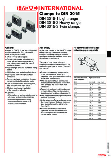
Installation and Wiring HandbookImportant InformationMODEL 2500 DIN RAIL CONTROLLERImportant Information1.SAFETY AND EMC INFORMATIONBefore installing the 2500 DIN rail controller, please ensure that you are familiar with ‘Safetyand EMC Information’. This is given in Appendix A at the back of this manual.2.EXITING CONFIGURATION MODEWhen exiting from configuration mode to normal operation, it is important to ensure that theoutput power demand levels from the controller are in a safe state for your process. In IOCsoftware releases prior to 2.21 this must be carried out manually, as follows:1. Before exiting configuration mode switch all PID loops into Manual2. Adjust the output to a level that is safe for the process. This would normally be zerooutput power.3. Exit configuration level.2500 DIN Rail Controllera-1
Important Informationa-2Installation and Wiring Handbook2500 DIN Rail Controller
2500 DIN Rail ControllerContentsMODEL 2500 DIN RAIL CONTROLLERINSTALLATION AND WIRING HANDBOOKCONTENTSChapter NoTopicImportant InformationChapter 1INTRODUCTION1-1What is 2500Before You BeginUnpacking1-11-41-4BASE 2500B2-1DescriptionIdentificationLayout and Dimensional DetailsDimensions and WeightsTo Mount The Base2-12-12-22-22-3TERMINAL UNITS 2500T3-1DescriptionTypes of Terminal UnitLabelsTo Mount Terminal UnitsTo Remove the Terminal UnitTo Fit Modules3-13-23-33-43-53-6MODBUS I/O CONTROLLER MODULE 2500C/S4-1DescriptionPosition on BaseThe Modbus IOC Terminal UnitTo Connect the 24Vdc Power SupplyTo Connect The Operator Interface UnitThe RJ45 Communications Line TerminatorThe Configuration PortTo Set The Address SwitchBaud RateStatus IndicationInitialisationPower On Self TestModes of 2Chapter 2Chapter 3Chapter 4Installation and Wiring HandbookPart No HA026178Pagea-1Issue 2.0 Aug-99i
ContentsChapter 5Chapter 6Chapter 7Chapter 8ii2500 Din Rail ControllerPROFIBUS I/O CONTROLLER MODULE 2500C/S5-1DescriptionPosition on BaseThe Profibus IOC Terminal UnitTo Connect an IOC in a Profibus DP NetworkProfibus 9 Pin D ConnectionsThe RJ45 IOC Terminal UnitTo Connect an IOC in a Profibus NetworkRJ45 Pin ConnectionsTo Connect the 24Vdc Power SupplyThe Configuration PortTo Set The Address SwitchBaud RateStatus IndicationInitialisationPower On Self TestModes of -115-115-11TWO CHANNEL ANALOGUE INPUT MODULE2500M/AI26-1DescriptionTerminal ConnectionsAnalogue Input Equivalent CircuitsStatus Indication6-16-26-46-6THREE CHANNEL ANALOGUE INPUT MODULE2500M/AI37-1DescriptionTerminal ConnectionsAnalogue Input Equivalent CircuitHart CompatibilityStatus Indication7-17-27-37-37-4TWO CHANNEL ANALOGUE OUTPUT MODULE2500M/AO28-1DescriptionTerminal ConnectionsAnalogue Output Equivalent CircuitsStatus Indication8-18-28-38-4Installation and Wiring HandbookPart No HA026178Issue 2.0 Aug-99
2500 DIN Rail ControllerChapter 9Chapter 10Chapter 11Chapter 12Chapter 13ContentsQUAD DIGITAL OUTPUT MODULE 2500M/DO49-1DescriptionTerminal ConnectionsDigital Output Equivalent CircuitsStatus Indication9-19-29-39-4QUAD DIGITAL INPUT MODULE 2500M/DI410-1DescriptionTerminal ConnectionsDigital Input Equivalent CircuitsStatus Indication10-110-210-310-4OCTAL DIGITAL INPUT MODULE 2500M/DI811-1DescriptionTerminal ConnectionsDigital Input Equivalent CircuitsStatus Indication11-111-211-311-4RELAY MODULE 2500M/RLY412-1DescriptionTerminal ConnectionsStatus Indication12-112-212-3POWER SUPPLY 2500P13-1DescriptionBrief SpecificationDimensions and WeightTo Mount The Power SupplyTo Detach From The DIN RailTerminal ConnectionsStatus Indication13-113-213-213-313-313-413-5EXAMPLES AND RECOMMENDATIONS14-1Power SupplyWire SizesExample Wiring DiagramOver Temperature Protection14-114-214-314-4Safety and EMC InformationA-1Technical SpecificationA-6Appendix BThe Ordering CodesB-1Appendix CTo Remove Snubber Circuits From The RelayModuleC-1Appendix DGlossary of TermsD-1Appendix EEurotherm Office AddressesE-1Chapter 14Appendix AInstallation and Wiring HandbookPart No HA026178Issue 2.0 Aug-99iii
Contents2500 Din Rail ControllerLIST OF FIGURES & TABLESFigure NumberFigure 1-1Figure TitleGeneral View of the 2500 DIN rail ControllerFigure 1-22500 Block Diagram1-3Figure 2-1Product Code Label2-1Figure 2-2The Base (Mounted Horizontally)2-2Table 2-1Dimensions and Weights2-2Figure 3-1General Layout of Module Base and Terminal Unit3-1Table 3-1Types of Terminal Unit3-2Figure 3-2Terminal Unit Labels3-3Figure 3-3Product Identification Labels3-3Figure 3-4IOC and AI2 ‘SHUNT’ Terminal Unit Labels3-3Figure 3-5Mounting the Terminal Units3-4Figure 3-6Module View3-6Figure 4-1Module Positions4-1Figure 4-2General View of the Modbus IOC Terminal Unit4-2Figure 4-3The Modbus RJ45 Connection System4-4Figure 4-4The Modbus RJ45 Terminator4-5Table 4-1Connections to the Modbus RJ45 Sockets4-5Table 4-2Connections to the RJ11 Sockets4-6Figure 4-5View of the Configuration RJ11 Plug and Socket4-6Figure 4-6Connection Between IOC and PC using RJ11 CableAssembly4-7Figure 4-7The Modbus Address Switch4-8Table 4-3Baud Rate4-8Figure 4-8IOC Status Indication4-9Figure 4-9Power On Self Test – LED Status Indication4-11ivInstallation and Wiring HandbookPart No HA026178Page1-1Issue 2.0 Aug-99
2500 DIN Rail ControllerContentsFigure 5-1Module Positions5-1Figure 5-2View of the 9 pin D Profibus IOC Terminal Unit5-2Figure 5-3Profibus Terminations on 9 Pin Connectors5-3Table 5-1Profibus 9 Pin D Connections5-3Figure 5-4View of the Profibus RJ45 IOC Terminal Unit5-4Figure 5-5The Profibus RJ45 Terminator5-5Table 5-2Connections to the Profibus RJ45 Sockets5-5Figure 5-6View of the Configuration RJ11 Plug and Socket5-7Table 5-3Connections to the RJ11 Sockets5-7Figure 5-7Connection Between IOC and PC using RJ11 CableAssembly5-8Figure 5-8The Profibus Address Switch5-9Figure 5-9IOC Status Indication5-10Figure 6-1aThe Dual Analogue Input Terminal Connections6-2Figure 6-1bThe Dual Analogue Input Terminal Connections6-3Figure 6-2Thermocouple Input Equivalent Circuit6-4Figure 6-33-WirePRT Input Equivalent Circuit6-4Figure 6-4Milli-Volt Input Equivalent Circuit6-5Figure 6-5Volt Input Equivalent Circuit6-5Figure 6-6Milli-Amp Input Equivalent Circuit6-5Figure 6-7Dual Analogue Input Status Indication6-4Figure 7-1Three Channel Analogue Input TerminalConnections7-2Figure 7-2mA Input Equivalent Circuit7-3Figure 7-3Three Channel Analogue Input Status Indication7-4Figure 8-1Two Channel Analogue Output TerminalConnections8-2Figure 8-2Voltage Output Equivalent Circuit8-3Figure 8-3Current Output Equivalent Circuit8-3Figure 8-4Two Channel Analogue Output Module StatusIndication8-4Installation and Wiring HandbookPart No HA026178Issue 2.0 Aug-99v
Contents2500 Din Rail ControllerFigure 9-1Quad Digital Output Module Terminal Connections9-2Figure 9-2Quad Digital Output Current Source EquivalentCircuit9-3Figure 9-3Quad Digital Output Voltage Switch EquivalentCircuit9-3Figure 9-4Quad Digital Output Module Status Indication9-4Figure 10-1Quad Digital Input Terminal Connections10-2Figure 10-2Quad Digital Input Voltage Source EquivalentCircuit10-3Figure 10-3Quad Digital Input Contact Closure EquivalentCircuit10-3Figure 10-4Quad Digital Input Module Status Indication10-4Figure 11-1Octal Digital Input Terminal Connections11-2Figure 11-2Octal Digital Input Contact Closure EquivalentCircuit11-3Figure 11-3Octal Digital Input Voltage Source EquivalentCircuit11-3Figure 11-4Octal Digital Input Module Status Indication11-4Figure 12-1Relay Module Terminal Connections12-2Figure 12-2Relay Module Status Indication12-3Figure 13-1General View of the 2500P Power Supply13-2Figure 13-2Mounting the 2500P Power Supply13-3Figure 13-3Detaching the 2500P Power Supply13-3Figure 13-42500P Power Supply Terminal Connections13-4Figure 13-52500P Power Supply Status Indication13-5Figure 14-1Example Wiring Diagram14-3Figure 14-2Over Temperature Protection14-5Figure C-1Removing the Rear Cover from the Relay ModuleC-1Figure C-2Removing the Case from the Relay ModuleC-2Figure C-3Removing Snubbers from the Relay Module PCBC-2viInstallation and Wiring HandbookPart No HA026178Issue 2.0 Aug-99
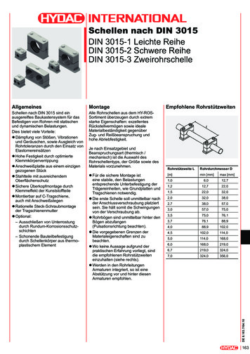
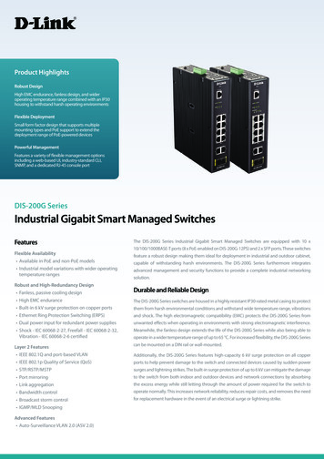
2500 DIN Rail ControllerIntroductionChapter 1 INTRODUCTIONThank you for selecting the EUROTHERM 2500 DIN Rail Controller.1.WHAT IS 2500The 2500 DIN Rail Controller is a modular I/O system with local PID control blocks and“User Wiring” allowing local computation and combinational logic. It is configured using Eurotherm “iTools” running on a personal computer under Windows 95, 98 or NT . Thestandard communications to it is Modbus RTU or Profibus DP.The 2500s are designed to work as flexible controllers in a number of possible architectures: as stand alone programmer/controllers using the Eurotherm type 2900 ¼ VGA display as front end control and data aquisition for third party PLCs and SCADA packages. as extension I/O for the 2600 and 2700 programmer/controllersThe unit is normally supplied as a number of separate parts, identified by a unique modelcode printed on labels attached to each item. These codes are explained in Appendix A.The parts can generally be classified as follows:the Base “2500B”the I/O Controller Module - “2500C”the I/O Modules “2500M”the Terminal Units “2500T”the 24V Power Supply “2500P.”2500C I/O Control Module2500B BaseUnitConfigurationport2500M Plug-inI/O ModulesDIN RailAddressswitchAI2DO4RLY4Optional Fusesor Isolator nsFigure 1-1: General View of the 2500 DIN rail ControllerportInstallation and Wiring HandbookPart No HA026178Issue 2.0 Aug-991-1
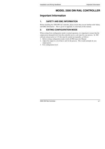
Introduction2500 DIN Rail ControllerThe 2500B Base can either be fixed onto a DIN rail or wall mounted. Three sizes of base areavailable, taking the 2500C I/O Controller Module plus 4, 8 or 16 2500M I/O Modules .The Terminal Units provide the wiring interface between the plant or machine and the I/Omodules. They can optionally be fitted with fuses or disconnects. The terminal unit alsocontains sockets into which the I/O Modules plug.Intercommunication between the I/O modules is effected by the use of the internal moduleI/O bus. The signals on this bus are transferred between modules through a series ofconnectors mounted on a printed circuit board running the full width of the base.Standard modules are:Module descriptionReferenceInput/output controller moduleIOCSee ordering codes -Universal isolated two channel analogue inputmoduleAI2Appendix B - for fullmodule and terminal unitcoding.Three channel mA analogue input withtransmitter power supplyAI3Universal two channel analogue output moduleAO2See also Table 3-1 forFour channel digital input moduleDI4a list of terminal unitsused withEight channel digital input moduleDI8each type ofFour channel digital output moduleDO4moduleFour channel relay moduleRLY4The Input Output Controller Module IOC (type 2500C), must always be fitted. It requires a24V supply and is available to provide four levels of functionality, as follows:1ACQIO23UW2LOOP42LOOPUW1-2Remote IO acquisition, makes all the I/O values available oncommunicationsAs 1 above, plus User WiringAs 1 above, plus 2 control blocks, each block may be single PID orcascade PIDs, and include self tune and gain scheduling.As 3 above, plus User WiringInstallation and Wiring HandbookPart No HA026178Issue 2.0 Aug-99
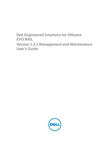
2500 DIN Rail ControllerIntroductionA diagrammatic representation of the 2500 DIN rail controller is shown in Figure 1-2.Internal I/O nit2500TModbus orProfibuscommunicationsto host PC orDisplay UnitPlant or Machine under controlFigure 1-2: 2500 Block DiagramInstallation and Wiring HandbookPart No HA026178Issue 2.0 Aug-991-3
Introduction1.1.2500 DIN Rail ControllerBefore You BeginBefore installing the 2500 DIN rail controller ensure that:All parts are of the correct type for the application. Check the advice note and/or label against the coding given in Appendix B for correct identities.The location and wiring requirements for each module is understood. Refer to the chapters covering installation for each of the hardware components. 1.2.UnpackingAll parts comprising the system are packaged in shipping containers designed to withstandreasonable transit shocks. It is suggested that each item is unpacked carefully and thecontents inspected for damage.If there is evidence of shipping damage, please notify Eurotherm within 72 hours. Thepackaging should be retained for inspection by a Eurotherm representative.All packaging contains anti-static materials to prevent the build up of static which candamage electronic assemblies.1-4Installation and Wiring HandbookPart No HA026178Issue 2.0 Aug-99
2500 DIN Rail ControllerBaseChapter 2 Base 2500B1.DESCRIPTIONThe base consists of an aluminium extrusion, the internal I/O bus and mounting supports.The internal I/O bus is a printed circuit board, mounted horizontally at the top of the base,and contains a number of sockets bussed together. It is used to carry the moduleintercommunication and power signals.The base is designed to be DIN rail mounted, using the fittings supplied, within an enclosure.If preferred, however, it can be bulkhead mounted directly on a mounting plate within theenclosure.The modules are mounted on the base using ‘Terminal Units’. These are described in moredetail in Chapter 3. Terminal Units correspond to the type of module supplied and arelocated on the base in the positions shown in Figure 2-2.Bases are available in three standard sizes to suit the number of modules required in aparticular system, and are finished with two plastic side covers. The dimensions and weightsof the three standard bases are detailed in table 2-1 overleaf.Safety earth and screen connections are made to clearly marked earth terminals at the bottomof the base.The assembly is shown in Figure 2-1.2.IDENTIFICATIONThe base may be identified by a label mounted on the rear of the unit, which shows modeltype and serial number.EUROTHERM(WORTHING - UK) 44(0) 1903 695888 (CONTROLS) 44(0) 1903 205222 (RECORDERS) 44(0) 1903 205277 (EUROTHERM PROCESS AUTOMATION)Product codeDate/cust refRatingFigure 2-1:Installation and Wiring HandbookProduct code labelPart No HA026178Issue 2.0 Aug-992-1
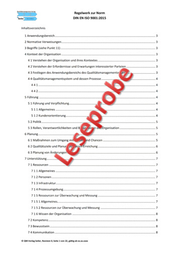
Base3.2500 DIN Rail ControllerLAYOUT AND DIMENSIONAL DETAILSModule positions. SeeI/O ‘POSITION ONBASE’ Figure ED②⑤Protective earth terminals①②Mounting screwBase retention clip③④⑤⑥⑦DIN railSide coverRetention clip for terminal unitSupport for terminal unitEMC earthing stripFigure 2-2: The Base (Mounted Horizontally)4.DIMENSIONS AND .0238.6441.8Dimensions 5.05.0Weights .12.7Table 2-1: Dimensions and Weights2-2Installation and Wiring HandbookPart No HA026178Issue 2.0 Aug-99
2500 DIN Rail Controller5.BaseTO MOUNT THE BASEThis unit is intended to be mounted within an enclosure, or in an environment suitable forIP20 rated equipment.It can be DIN rail or bulkhead mounted.For DIN rail mounting, use symmetrical DIN rail to EN50022-35 X 7.5 or 35 X 15 mountedhorizontally or vertically.! CautionDo not operate the equipment without a protective earth conductor connected to one of theearth terminals on the base unit.The earth cable should have at least the current rating of the largest power cable used toconnect to the unit.Connect the protective earth with a suitable tinned copper eyelet, and use the screw andwasher supplied with the base unit, tightened to a torque of 1.2Nm 910.5lbin).This connection also provides a ground for EMC purposes.5.1.DIN Rail Mounting (horizontal)1.Mount the DIN rail horizontally, using suitable bolts.2.Ensure that the DIN rail makes good electrical contact with the metal base of theenclosure.3.Loosen screws ① in the base, and allow them, and the associated base retention clips②, to drop to the bottom of the screw slot.4.In the back of the base is an extruded slot which locates with the DIN rail ③.5.Fit the top edge of this into the top edge of the DIN rail ③6.Slide the screws ① with the associated clips ② upwards as far as they will go towardsthe top of the screw slots The angled edge of the base retaining clip ② must locatebehind the bottom edge of the DIN rail.7.Tighten the screws ①.Installation and Wiring HandbookPart No HA026178Issue 2.0 Aug-992-3
Base2500 DIN Rail Controller5.2.DIN Rail Mounting (vertical)Caution! It is acceptable to mount the 2500 base vertically. If it is mounted vertically,however, it is advisable to fit a fan in the cubicle to ensure a free flow of air around themodules.1.Mount the DIN rail vertically, using suitable bolts.2.Ensure that the DIN rail makes good electrical contact with the metal base of theenclosure.3.Loosen screws ① in the base, and move them, and the associated base retention clips②, to the bottom of the screw slot.4.In the back of the base is an extruded slot which locates with the DIN rail ③.5.Fit the top edge of this into the top edge of the DIN rail ③6.Slide the screws ① with the associated clips ② upwards as far as they will go towardsthe top of the screw slots The angled edge of the base retaining clip ② must locatebehind the bottom edge of the DIN rail.7.Tighten the screws ①.5.3.Direct Panel Mounting1.Remove the screws ① and base retention clips ②.2.Hold the base horizontally or vertically on the panel and mark the position of the twoholes on the panel.3.Drill two 5.2 mm holes in the panel.4.Using M5 bolts secure the base to the metal panel.2-4Installation and Wiring HandbookPart No HA026178Issue 2.0 Aug-99
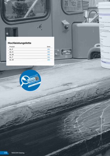
2500 DIN Rail ControllerTerminal UnitsChapter 3 Terminal Units 2500T1.DESCRIPTIONTerminal units provide the connections between the plant wiring and the I/O modules. Eachmodule has its own type of terminal unit. Some modules have more than one type of terminalunit, for example, the analogue input module has three basic types of terminal unit:1. with CJC measurement for thermocouples2. without CJC for input signals such as V, mV, PRTs, etc.3. with built in 5Ω shunt resistors for mA inputsIn addition to these variants, some terminal units can have built in fuses or isolator links. Fora full list of available terminal units see Table 3-1.I/O Module interconnection busIdentityLabelModule locking grommetAI2Terminal unitModule connectorsOptional plug in fuses orisolator links useNote:- Fuse andisolator links haveoffset connectorsLinkShows fuse or link positionsTerminal blocks to plant devicesRetention clip for terminal unitScreen and earthconnectionsFigure 3-1: General Layout of Module Base and Terminal UnitInstallation and Wiring HandbookPart No HA026178Issue 2.0 Aug-993-1
Terminal Units1.1.2500 DIN Rail ControllerIsolator links and Fuses (optional)Up to four isolator links or fuses are available as options for certain modules.Isolator links disconnect plant connections from the module (for testing and commissioning).The fuses supplied for the relay units are 2A (T type), 20mm to EN60127.Fuses of a lower rating may be fitted to suit the application.The label on the side of the fuse holder may be used to indicate the correct type of fuse.The label on the top of the fuse holder may be used to identify or tag the protected circuit. Ifisolator links or fuses are not fitted then a dummy fuse cover is fitted to provide this function.2.TYPES OF TERMINAL UNITTerminalUnit NameAI2Corresponding Module TypeIsolatorlinkNoneDual channel Analogue Input, with 4connections and common per channelDual Channel Analogue Input, with a 5Ωshunt resistor across each inputDual Channel Analogue Input, with CJCAI2SHUNTAI2TCAI33 channel mA inputAI33 individual link breakers on current i/p onthDCONNECT each loop, 4 breaks PSU for all 3 IBUSNoneNoneFunctionV, mVPRT, Hi Z, PotmA inputT/C inputmVmA inputmA inputNone4 links(only 3are used)Dual Channel Analogue Output, for volts or NoneV,mA outputmA outputsDual Channel Analogue Output, for volts or 2 x links V,mA outputmA outputs2 xblanksFour Channel Digital Input, with common NoneLogic inputand external power supply terminalsFour Channel Digital Input, with common 4 x links Logic inputand external power supply terminalsFour pairs of functionally isolated inputs,4 X links Logic inputcontact closure or 24V logic inputcontactFour pairs of functionally isolated inputs,NoneLogic inputcontact closure or 24V logic inputcontactFour Channel Digital Output, with common NoneLogic outputand external power supply terminalsFour Channel Digital Output, with common 4 x links Logic outputand external power supply terminalsFour Isolated Channels for relaysNoneRelay outputFour Isolated channels for relays4 x fuses Relay outputSpecific for IOC with Modbus; two RJ45connectors and address select switchSpecific for IOC with Profibus; one 9 wayconnector and address select switchSpecific for IOC with Profibus; two RJ45connectors and address select switchN/AIOCN/AIOCN/AIOCTable 3-1: Types of Terminal Unit3-2Installation and Wiring HandbookPart No HA026178Issue 2.0 Aug-99
2500 DIN Rail Controller3.Terminal UnitsLABELS1 2 3 4Terminal unit labels are fitted to the sloping facesof each terminal block, as shown.C C C CV V- C CFigure 3-2: Terminal Unit Labels (Example Only)On units fitted with either fuses or disconnects theproduct code label is fitted to the side of thefuse/disconnect assembly.Figure 3-3: Product Identification LabelIn the case of the AI2 DC Shunt, a label marked ‘SHUNT’ is fittedin the screen printed outline of the printed circuit board.On the IOC terminal unit the product code label is fitted in thisposition.Figure 3-4: IOC and AI2 ‘SHUNT’ Terminal Unit LabelsInstallation and Wiring HandbookPart No HA026178Issue 2.0 Aug-993-3
Terminal Units4.2500 DIN Rail ControllerTO MOUNT TERMINAL UNITSNotes:1. The far left position is always reserved for the Input/Output Controller. (IOC), and isidentified by the larger connector on the I/O module interconnection bus2. All other terminal units can be fitted in any other position on the base.3. In the event that the base is not fully populated a blank terminal unit is supplied, partnumber 026373. To maintain IP20 rating it is important that this unit is mountedimmediately to the right of the final module position.M7M8IOC2.Locate tag on printedcircuit board with slotin baseAI2EMC earthing stripBlank Terminal Unit(Part number 026373)See note 3 aboveModule support strip2.Press the bottom ofthe retention clip andsnap the terminal unitinto placeFigure 3-3: Mounting the Terminal Units3-4Installation and Wiring HandbookPart No HA026178Issue 2.0 Aug-99
2500 DIN Rail Controller5.Terminal UnitsTO REMOVE THE TERMINAL UNIT1. Remove any I/O module which is plugged into the terminal unit2. Press the retention clip at the bottom of the terminal unit3. Lift out the terminal unitInstallation and Wiring HandbookPart No HA026178Issue 2.0 Aug-993-5
Terminal Units6.2500 DIN Rail ControllerTO FIT MODULESEach I/O module is supplied as a moulded plastic enclosure with the printed circuit boardmounted internally. A polarising key is built into the printed circuit board which locates witha corresponding slot in the correct terminal unit. A row of LED indicators show the status ofthe module and are described in further detail in subsequent chapters.Module retaining lever(closed)ModuleretainingcatchLED statusindicatorsModule Label90 mmModule retaininglever openPolarisingkey position.See table 3-181 mm25 mm114 mmFigure 3-4: Module viewImportant1.2.Pull the module retaining lever forwards as shown in Figure 3-4Line up the module in the correct terminal unit. The plugs on the module PCB shouldalign with the sockets on the terminal unit and module interconnection bus. The moduleretaining catch should align with the corresponding hole in the terminal unit.Note: A polarising key is provided on the module PCB which is designed to prevent amodule from being inserted into the incorrect terminal unit.3. When the module is correctly aligned, push the module retaining lever forwards to lockthe module into place.Wiring of the 2500 can take place with only the terminal units fitted or after the moduleshave been fitted, as preferred. Wiring is described in following chapters.3-6Installation and Wiring HandbookPart No HA026178Issue 2.0 Aug-99
2500 DIN Rail ControllerChapter 4Modbus IOC ModuleModbus I/O Controller Module2500C/S1.DescriptionThe Input Output Controller (IOC) is the Central Processing Unit of the 2500 DIN railcontroller. Every base must have an IOC module. It is identified by a label on the side of themodule which gives details of model and serial number. The model number should bechecked against the Ordering Code, explained in Appendix B of this manual.This module: Communicates with the slave modules connected to the internal IO bus, using the ModuleInterconnection printed circuit board mounted along the upper edge of the base. Communicates to external devices, such as third party PLCs and SCADA packages, usingRJ45 connection cables and, optionally, using MODBUS comms. This is sometimesreferred to as the I/O network or ION. (See also section 5 of this chapter). Examples ofexternal devices are: to connect to the operator interface unit; to connect to a supervisory PC; to link further slave 2500 controllers in a system; to link further external devices such as discrete controllers, indicators, chartrecorders, drives, etc. Is used for system configuration, using the front panel RJ11 socket. Systemconfiguration uses Eurotherm iTools, and is covered in a separate manual, Eurotherm partno. HA026179.This chapter explains how connections are made to the IOC to achieve the above operation.2.Position on BaseThe IOC always occupies the slot furthest to the left hand 8IOC12345678910111213141516Figure 4-1: Module PositionsNote: The numbering used to define the physical location of each module, as shown in theabove sketch, is the same as that used when configuring the modules.Installation and Wiring HandbookPart No HA026178Issue 2.0 Aug-994-1
Modbus IOC Module3.2500 DIN Rail ControllerThe Modbus IOC Terminal UnitThis unit provides: Terminal connections for the 24V DC supply to the system RJ45 comms connectors to the Operator Interface Unit and additional plant devices An IOC communication address switch A PCB mounted socket for the IOC module connectionsThe IOC terminal blockhas two location tags,and can only be fitted inthe left most position.All other units have asingle tagMaster Operatorinterface unitor PLCor SupervisorySystem123Fit links in postions:1 - 2 for 2 (3) wireModbus (default)2 – 3 for 4 (5) wireModbusNote: Earlier units werefitted with a single link for2(3) wire or no link for4(5) wire.Suitable terminationsshould be made to bothends of the networkUnit addressswitchPolarisingslot position89.8 mmRJ45 commsconnector to PC.See note 1Furtherinstrumentsfitted withModbuscomms.RJ45 comms connectorto other system devices.See note 1.P P P-P-2 terminals each(for daisy chaining) 24V0VNote 1:The plastic cover supplied must be fitted over theRJ45 socket when the connector is not in useTermination plug on lastdevice in the chainFigure 4-2: General View of the Modbus IOC Terminal Unit4-2Installation and Wiring HandbookPart No HA026178Issue 2.0 Aug-99
2500 DIN Rail Controller4.Modbus IOC ModuleTo Connect the 24Vdc Power SupplyCaution: Before proceeding with any wiring of this unit, please read Chapter 14 Wiring,and Appendix A Safety and EMC Information. It is the responsibility of the installer toensure the safety and EMC compliance of any particular installation.The power supply to the 2500 DIN rail controller is 24V DC. This may be derived from the2500P power supply unit or from an alternative 24V DC source. Connections to the systemare through the four way terminal block mounted on the IOC terminal unit. Unless otherwisestated power is supplied to all other modules in the system via the module interconnectionbus.A suitable power supply is the 2500P described in Chapter 13 of this manual. This is a DINrail mounted unit which may be mounted adjacent to the 2500 base or remotely.Alternatively, an existing power supply may be used provided that it has a voltage output of1between 18.0 to 28.8V DC.To calculate the system current requirements an estimate of current ratings for each module isgiven in Chapter 13, Section 1.The IOC terminal unit contains a fuse and a reverse biased power diode. If the power iswired reverse polarity the fuse will blow and protect the complete 2500 base from damage.This fuse is not user replaceable. The unit should be returned to the factory for replacement.Note 1:- 18V is the absolute lower limit. The use of an 18V power supply with anyappreciable voltage drop may cause unpredictable or out of specification operation.Installation and Wiring HandbookPart No HA026178Issue 2.0 Aug-994-3
Modbus IOC Module5.2500 DIN Rail ControllerTo Connect an Operator Interface UnitTwo parallel connected RJ45 communications sockets are provided. The two sockets,therefore, have the same function.One socket is used to connect the 2500 to an Operator Interface Unit, such as type T2900 ORto a conventional SCADA system. This will also allow configuration via iTools.The second socket provides a convenient way to connect additional 2500 instruments ontothe system, OR to terminate the last instrument in the chain using a MODBUS or PROFIBUSterminator, see 4.1. The terminator may also be used to terminate the 2900 Operator InterfaceUnitThe above devices are connected using RJ45 interconnection cables. These are availablefrom Eurotherm Cont
Contents 2500 Din Rail Controller iv Installation and Wiring Handbook Part No HA026178 Issue 2.0 Aug-99 LIST OF FIGURES & TABLES Figure Number Figure Title Page Figure 1-1 General View of the 2500 DIN rail Controller 1-1 Figure 1-2 2500 Block Diagram 1-3 Figure 2-1 Product Code Label 2-1 Figure 2-2 The Base (Mounted Horizontally) 2-2