Transcription
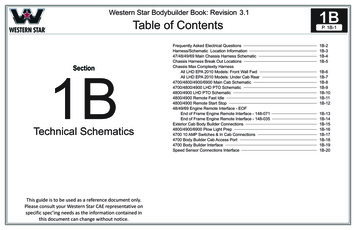
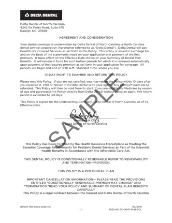
ANSI Z359.11OSHA 1926.502Delta OSHA 1910.140Full Body HarnessUSER INSTRUCTIONS5903124 Rev. G910111213141516Parachute AdjusterRevolver AdjusterTrauma StrapsSeat SlingTool LoopLanyard Keeper8Leg Pad7Belt and Hip Pad6Shoulder and Back Pads5Pass-Through Buckle4Tongue Buckle163Quick Connect Buckle122Hip6115Sternal11D-Ring B14 2 3 4 5 6 7 8 910 11 12 13 A14B15A Buckles 1AAttachmentElements Pads Other Elements 19B20 A 1718 16B B10 3M 2020
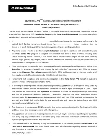
910111213141516Parachute AdjusterRevolver AdjusterTrauma StrapsSeat SlingTool LoopLanyard Keeper8Leg Pad7Belt and Hip Pad6Shoulder and Back Pads5Pass-Through Buckle4Tongue Buckle163Quick Connect Buckle122Hip6115Sternal11D-Ring ementsBuckles 22 23 24 25 26 27 28 29 30 32 33 35 36 Other Elements Pads 21319DModelGroup
2ABCDE3F4ABBFCCCFC56ABEABCDFGC7AB3C
8BACü üD91ABCLCICK!23AB10AB4
11121234565
13A14124356
15A1617A7
18ANSI/OSHA132ANSI Z359.11-2014ANSI Z359 Recognizes the use of thisharness only within the capacity range of:130-310 lbs.Model No.:Mfrd.(yr/mo):PRODUCT COMPLIANCELot:DO NOT REMOVE THIS LABELUSER IDENTIFICATIONMark label withpermanent markerINSPECTION LOG458Stds:
SAFETY INFORMATIONENPlease read, understand, and follow all safety information contained in these instructions prior to the use of thisFull Body Harness. FAILURE TO DO SO COULD RESULT IN SERIOUS INJURY OR DEATH.These instructions must be provided to the user of this equipment. Retain these instructions for future reference.Intended Use:This Full Body Harness is intended for use as part of a complete personal fall protection system.Use in any other application including, but not limited to, material handling, recreational or sports related activities, or otheractivities not described in the User Instructions, is not approved by 3M and could result in serious injury or death.This device is only to be used by trained users in workplace applications.!!WARNINGThis Full Body Harness is part of a personal fall protection system. It is expected that all users be fully trained in the safeinstallation and operation of their personal fall protection system. Misuse of this device could result in serious injuryor death. For proper selection, operation, installation, maintenance, and service, refer to these User Instructions and allmanufacturer recommendations, see your supervisor, or contact 3M Technical Service. To reduce the risks associated with working with a Full Body Harness which, if not avoided, could result inserious injury or death:-- Inspect the device before each use, at least annually, and after any fall event. Inspect in accordance with the UserInstructions.-- If inspection reveals an unsafe or defective condition, remove the device from service and destroy it.-- Any device that has been subject to fall arrest or impact force must be immediately removed from service anddestroyed.-- Ensure the harness is worn correctly, appropriately sized, and properly adjusted.-- Ensure all connecting subsystems (e.g. lanyards) are kept free from all hazards including, but not limited to,entanglement with other workers, yourself, moving machinery, or other surrounding objects.-- Ensure that fall protection systems/subsystems assembled from components made by different manufacturers arecompatible and meet the requirements of applicable standards, including the ANSI Z359 or other applicable fallprotection codes, standards, or requirements. Always consult a Competent or Qualified Person before using thesesystems. To reduce the risks associated with working at height which, if not avoided, could result in serious injury ordeath:-- Ensure your health and physical condition allow you to safely withstand all of the forces associated with working atheight. Consult with your doctor if you have any questions regarding your ability to use this equipment.-- Never exceed allowable capacity of your fall protection equipment.-- Never exceed maximum free fall distance of your fall protection equipment.-- Do not use any fall protection equipment that fails pre-use or other scheduled inspections, or if you have concerns aboutthe use or suitability of the equipment for your application. Contact 3M Technical Services with any questions.-- Some subsystem and component combinations may interfere with the operation of this equipment. Only use compatibleconnections. Consult 3M prior to using this equipment in combination with components or subsystems other than thosedescribed in the User Instructions.-- Use extra precautions when working around moving machinery (e.g. top drive of oil rigs), electrical hazards, extremetemperatures, chemical hazards, explosive or toxic gases, sharp edges, or below overhead materials that could fall ontoyou or your fall protection equipment.-- Use Arc Flash or Hot Works devices when working in high heat environments.-- Avoid surfaces and objects that can damage the user or equipment.-- Ensure there is adequate fall clearance when working at height.-- Never modify or alter your fall protection equipment. Only 3M or parties authorized in writing by 3M may make repairs tothe equipment.-- Prior to use of fall protection equipment, ensure a rescue plan is in place which allows for prompt rescue if a fall eventoccurs.-- If a fall event occurs, immediately seek medical attention for the worker who has fallen.-- Do not use a body belt for fall arrest applications. Use only a Full Body Harness.-- Minimize swing falls by working as directly below the anchorage point as possible.-- If training with this device, a secondary fall protection system must be utilized in a manner that does not expose thetrainee to an unintended fall hazard.-- Always wear appropriate personal protective equipment when installing, using, or inspecting the device/system.FORM NO: 5908245 REV: A9
;;Before using this equipment, record the product identification information from the ID label in the “Inspection andMaintenance Log” at the back of this manual.;;Always ensure you are using the latest revision of your 3M instruction manual. Visit the 3M website or contact 3MTechnical Services for updated instruction manuals.DESCRIPTIONFigure 1 defines available 3M DBI-SALA Delta Full Body Harness models. Harness models are defined by their generalconstruction and available features. Within Figure 1, “Harness Style” illustrates general construction and “Model List” groupsHarnesses by available features. For information on which Model List your Harness belongs to, see “Harness Models” on thefollowing pages.SPECIFICATIONSPerformance:Maximum Free Fall Distance1.8 m (6 ft)Maximum Arresting Force8 kN (1,800 lbs)Capacity140 kg (310 lbs) ANSI160 kg (352 lbs) CSAApproximate WeightHarness only: 3 lbs (1.4 kg)Harness with Side D-rings: Add ½ lb (.23 kg)Harness with Back Pad or Belt: Add 1 lb (.45 kg)Materials:WebbingPolyester - 27 kN (6,000 lbs) Tensile StrengthNylon - 31 kN (7,000 lbs) Tensile StrengthNomex covered Kevlar - 31 kN (7,000 lbs) Tensile StrengthPad CoversBlend of Nylon and Polyester; Nomex covered Kevlar Label CoverBlend of Nylon and Polyester; Nomex covered Kevlar ThreadPolyester Thread on Polyester WebbingNylon Thread on Nylon WebbingD-RingsAluminum Alloy - 22 kN (5,000 lbs) Tensile StrengthQuick Connect ConnectorsAluminum Alloy, Stainless Steel, and Alloy Steel - 18 kN (4,000 lbs) Tensile StrengthRevolver AdjustersAluminum Alloy, Stainless Steel, Alloy Steel, and Nylon - 18 kN (4,000 lbs) Tensile StrengthOptional Accessories: Delta Full Body Harnesses are available with different options and accessories. Below is a partial listof commonly used options and accessories. NOTE: Some options may not be available on all harnesses.Hip Pad with side D-ringArc-rated hip, leg, and back padsNomex covered Kevlar webbingPolyurethane coated, arc-rated dorsal web loopNon-sparking/non-conductive PVC coated hardwareTool belt support strapsArc FlashHarness meets the test requirements of the ASTM F887-11standard and is designed for use in environments where anarc flash (electrical explosion) could occur.Harness ModelsEach Model List corresponds to a different Harness Style, as seen in Figure 1. For a list of Harness features within each ModelList, see Figure 1.Each Harness model within the Model List is available in different sizes. To determine what size your Harness is, refer to thetopmost portion of the label strap (A), as seen in Figure 17.For a list of models within each Model List, see next page.10
Harness ModelsModel Group(Figure 1)Harness Type(Figure 1233011105861110587ABCC11
Harness ModelsModel Group(Figure 0180111018021101805110181125Harness Type(Figure 8184110251611081851108186D
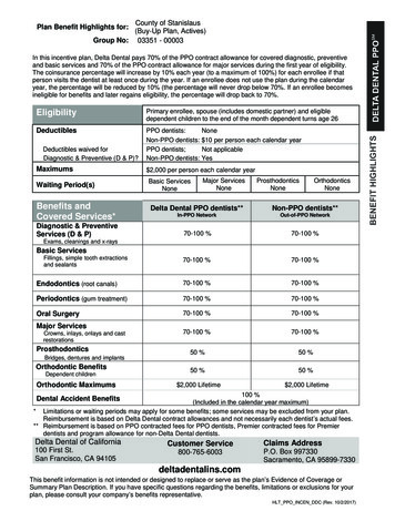
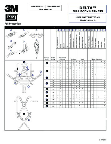
1.0APPLICATIONS1.1PURPOSE: Full Body Harnesses are to be used as components in Personal Fall Protection System designed to prevent afall or safely arrest a fall (see Figure 2). Full Body Harnesses are used in the following applications:AFall Arrest: Personal fall arrest systems typically include a Full Body Harness and a connecting subsystem (Energy Absorbing Lanyard, Self-RetractingDevice, etc.). Maximum arresting force must not exceed 1,800 lbs (8 kN).Attachment Elements: Dorsal (feet first with a 2 ft. maximum free fall when using a Self-Retracting Device or 6 ft. maximum free fall when using anEnergy Absorbing Lanyard), Sternal (feet first with a 2 ft. maximum free fall), Frontal (feet first with a 2 ft. maximum free fall).BWork Positioning: Work positioning systems typically include a Full Body Harness, positioning lanyard, and a back-up personal fall arrest system. Forwork positioning applications, connect the work positioning subsystem (example: lanyard, Y-lanyard, etc.) to the lower (hip level) side or belt mountedwork positioning attachment anchorage elements (D‑Rings). Never use these connection points for fall arrest.Attachment Elements: Frontal, Hip.CClimbing: The Full Body Harness is used as a component of a climbing system to prevent the user from falling when climbing a ladder or other climbingstructure. Climbing systems typically include a Full Body Harness, vertical cable or rail attached to the structure, and climbing sleeve. For ladder climbingapplications, harnesses equipped with a frontal D-Ring in the sternal location may be used for fall arrest on fixed ladder climbing systems.Attachment Elements: SternalDRescue: The Full Body Harness is used as a component of a rescue system. Rescue systems are configured depending on the type of rescue. For limitedaccess (confined space) applications, harnesses equipped with D-Rings on the shoulders may be used for entry and egress into confined spaces whereworker profile is an issue.Attachment Elements: Dorsal, Sternal, Frontal, ShoulderEControlled Descent: For controlled descent applications, harnesses equipped with a single sternal level D‑Ring, one or two frontal mounted D‑Rings, ora pair of connectors originating below the waist (such as a seat sling) may be used for connection to a descent or evacuation system.Attachment Elements: Dorsal Sternal, FrontalFRestraint: The Full Body Harness is used as a component of a restraint system to prevent the user from reaching a fall hazard. Restraint systemstypically include a Full Body Harness and a lanyard or restraint line.Attachment Elements: Dorsal, Sternal, Frontal, Hipapplication and work conditions require the use of Full Body Harnesses with specific attributes:;; CertainFull body harnesses with Kevlar web should be used when working with tools, materials, or environments of high temperature (foundries, chemicalmanufacturing, steel fabrication, emergency rescue services, fire services, welders, oil industry, nuclear industry, explosives). Harnesses with PVC coated hardware should be used when working in explosive or electrically conductive environments, or where surfaces must beprotected from the hardware. Harnesses with high visibility webbing should be used when increased visibility of the user is required.1.2STANDARDS: Harnesses included in this manual conform to the standard(s) identified on the front cover of this instructionand in Table 1. If this product is resold outside the original country of destination, the re-seller must provide theseinstructions in the language of the country in which the product will be used.1.3TRAINING: It is the responsibility of the user and the purchaser of this equipment to assure that they are familiar withthese instructions, trained in the correct care and use of, and are aware of the operating characteristics, application limits,and the consequences of improper use of this equipment.1.4LIMITATIONS: Always consider the following application limitations before using this equipment:1 CAPACITY: The Full Body Harness is designed for use by persons with a combined weight (clothing, tools, etc.)ranging from 130 lbs (59 kg) to 310 lbs (140 kg). Make sure all of the components in your system are rated to acapacity appropriate to your application. FREE FALL: Personal fall arrest systems used with this equipment must be rigged to limit the free fall to 6 feet (1.8m)1. Restraint systems must be rigged so that no vertical free fall is possible. Work positioning systems must berigged so that free fall is limited to 2 feet (.6 m) or less. Personnel riding systems must be rigged so that no verticalfree fall is possible. Climbing systems must be rigged so that free fall is limited to 18 in. (.46 cm) or less. Rescuesystems must be rigged so that no vertical free fall is possible. See subsystem manufacturer’s instructions for moreinformation. FALL CLEARANCE: Figure 3 illustrates the components of a Fall Arrest. There must be sufficient Fall Clearance (FC)to arrest a fall before the user strikes the ground or other obstruction. Clearance is affected by a number of factorsincluding: (A) Lanyard Length, (B) Lanyard Deceleration Distance or SRL Maximum Arrest Distance, (C) HarnessStretch and D-Ring/Connector Length and Settling (typically a Safety Factor of 1.5 ft). Refer to the instructionsincluded with your Lanyard or Self-Retracting Device for specifics regarding Fall Clearance calculation. SWING FALLS: Swing Falls occur when the anchorage point is not directly above the point where a fall occurs (see Figure4). The force of striking an object in a swing fall may cause serious injury or death. Minimize swing falls by working asdirectly below the anchorage point as possible. Do not permit a swing fall if injury could occur. Swing falls will significantlyincrease the clearance required when a Self-Retracting Device or other variable length connecting subsystem is used. EXTENDED SUSPENSION: A Full Body Harness is not intended for use in extended suspension applications. If theuser is going to be suspended for an extended length of time it is recommended that some form of seat support beused. 3M recommends a seat board, suspension work seat, seat sling, or a boatswain chair. Contact 3M for moreinformation on these items. ENVIRONMENTAL HAZARDS: Use of this equipment in areas with environmental hazards may require additionalprecautions to prevent injury to the user or damage to the equipment. Hazards may include, but are not limitedto; heat, chemicals, corrosive environments, high voltage power lines, gases, moving machinery, and sharp edges.Although PVC coated and zinc plated hardware exhibit excellent corrosion resistance in chemical, acidic, alkaline,and atmospheric conditions, frequent inspections may be required. Consult with 3M if you question the use of thisequipment in hazardous environments. HARNESSES FOR HIGH TEMPERATURE ENVIRONMENTS: Harnesses with Kevlar webbing are designed for use inhigh temperature environments, with limitations: Kevlar webbing begins to char at 800 to 900 Fahrenheit. Kevlarwebbing can withstand limited contact exposure to temperatures up to 1,000 F. Polyester webbing loses strengthat 300 to 400 F. PVC coating on hardware has a melting point of approximately 350 F. When working with tools,materials, or in high temperature environments, ensure that associated fall protection equipment can withstand highFall Arrest Free Falls: Free falls greater than 6 ft. (1.8 m) may be permitted when users are secured to the anchorage with a connecting subsystem which limits maximum arresting force to 1,800 lbs (8 kN) and is authorized for such use (i.e., DBI-SALA Force 2 Lanyards).13
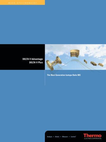
temperatures, or provide protection for those items.2.0SYSTEM USE2.1RESCUE PLAN: When using this equipment and connecting subsystem(s), the employer must have a rescue plan and themeans at hand to implement and communicate that plan to users2, authorized persons3, and rescuers4.2.2INSPECTION FREQUENCY: The Full Body Harness shall be inspected by the user before each use and by a competentperson5 other than the user at intervals of no more than one year6. Inspection procedures are described in the “Inspectionand Maintenance Log”. Results of each Competent Person inspection should be recorded on copies of the “Inspection andMaintenance Log” or tracked with a Radio Frequency Identification (RFID) system (see “Inspection”).2.3COMPATIBILITY OF COMPONENTS: 3M equipment is designed for use with 3M approved components and subsystemsonly. Substitutions or replacements made with non-approved components or subsystems may jeopardize compatibility ofequipment and may effect the safety and reliability of the complete system.2.4COMPATIBILITY OF CONNECTORS: Connectors are compatible with connecting elements when they have beendesigned to work together in such a way that their sizes and shapes do not cause their gate mechanisms to inadvertentlyopen regardless of how they become oriented. Contact Capital Safety if you have any questions about compatibility.Connectors (hooks, carabiners, and D-Rings) must be capable of supporting at least 5,000 lbs. (22.2 kN). Connectorsmust be compatible with the anchorage or other system components. Do not use equipment that is not compatible.Non-compatible connectors may unintentionally disengage (See Figure 5). Connectors must be compatible in size, shape,and strength. If the connecting element to which a snap hook (shown) or carabiner attaches is undersized or irregular inshape, a situation could occur where the connecting element applies a force to the gate of the snap hook or carabiner.This force may cause the gate (of either a self-locking or a non-locking snap hook) to open, allowing the snap hook orcarabiner to disengage from the connecting point. Self-locking snap hooks and carabiners are required.2.5MAKING CONNECTIONS: Use only self-locking snap hooks and carabiners with this equipment. Use only connectors thatare suitable for each application. Ensure all connections are compatible in size, shape and strength. Do not use equipmentthat is not compatible. Ensure all connectors are fully closed and locked.3M connectors (snap hooks and carabiners) are designed to be used only as specified in each product’s user’s instructions.See Figure 6 for inappropriate connections. 3M snap hooks and carabiners should not be connected:A. To a D-Ring to which another connector is attached.B. In a manner that would result in a load on the gate.C. In a false engagement, where features that protrude from the snap hook or carabiner catch on the anchor, andwithout visual confirmation seems to be fully engaged to the anchor point.D. To each other.E. Directly to webbing or rope lanyard or tie-back (unless the manufacturer’s instructions for both the lanyard andconnector specifically allows such a connection).F. To any object which is shaped or dimensioned such that the snap hook or carabiner will not close and lock, or thatroll-out could occur.G. In a manner that does not allow the connector to align properly while under load.2.6CONNECTING SUBSYSTEMS: Connecting subsystems (self-retracting lifeline, lanyard, rope grab and lifeline, cable sleeve,etc.) must be suitable for your application (See section 1.1). See the subsystem manufacturer’s instructions for additionalinformation. Some harness models have web loop connection points. Do not use snap hooks to connect to web loops. Usea self-locking carabiner to connect to a web loop. Ensure the carabiner cannot cross-gate load (load against the gate ratherthan along the major axis of the carabiner). Some lanyards are designed to choke onto a web loop to provide a compatibleconnection. Lanyards may be sewn directly to the web loop forming a permanent connection. Do not make multipleconnections onto one web loop, unless choking two lanyards onto a properly sized web loop. To choke the lanyard on a webloop (Figure 7): A) Insert the lanyard web loop through the web loop or D-Ring on the harness. B) Insert the appropriateend of the lanyard through the lanyard web loop. C) Pull the lanyard through the connecting web loop to secure.2.7LANYARD PARKING ATTACHMENT: Figure 8 illustrates Lanyard Parking. The Lanyard Parking Attachment is forattaching the free end of a Lanyard or harness mounted Self-Retracting Device when not connected to an AnchorageConnection Point for purposes of fall protection. Lanyard Parking Attachments must never be used as a Fall ProtectionAttachment Element on the Harness for connecting a Lanyard or Self-Retracting Device (A).When not connected to an Anchorage Connection Point, an unconnected Lanyard Leg must be properly parked on theharness (B) or secured in the user’s hand as in 100% Tie-Off applications (C). Free hanging Lanyard Legs (D) can trip theuser or catch on surrounding objects resulting in a fall.2345User: A person who performs activities at heights while protected by a personal fall protection system.Authorized Person: A person assigned by the employer to perform duties at a location where the person will be exposed to a fall hazard.Rescuer: Person or persons other than the rescue subject acting to perform an assisted rescue by operation of a rescue system.Competent Person: One who is capable of identifying existing and predictable hazards in the surroundings or working conditions which are unsanitary, hazardous, ordangerous to employees, and who has authorization to take prompt corrective measures to eliminate them.6 Inspection Frequency: Extreme working conditions (harsh environments, prolonged use, etc.) may require increasing the frequency of competent person inspections.14
3.0HARNESS USE3.1BEFORE EACH USE of this equipment inspect it according to the “Inspection and Maintenance Log” (Table 1).3.2PLAN y our system before use. Consider all factors that will affect your safety during use of this equipment. The followinglist gives important points to consider when planning your system:3.3 Anchorage: Select an anchorage capable of sustaining the Static Load requirements of the intended fall protectionapplication (see Section 1.1). The anchorage location should address Free Fall, Fall Clearance, Swing Fall, andEnvironmental limitations described in Section 1.4. Sharp Edges: Avoid working where system components may be in contact with, or abrade against, unprotectedsharp edges. After A Fall: Components which have been subjected to the forces of arresting a fall must be removed from serviceand destroyed. Rescue: The employer must have a rescue plan when using this equipment. The employer must have the ability toperform a rescue quickly and safely. Rescue Harness: Rescue Harnesses are intended to be worn during normal work activities. Before using rescueattachment elements for the first time, the user should carry out a suspension test in safe conditions to ensure theharness is sized and fitted for optimal comfort during suspension.BUCKLES: Delta Full Body Harnesses are equipped with buckles for fastening and adjusting Leg Straps and ChestStraps. Harness Body Belts have a Tongue Buckle. Figure 9 illustrates operation of each of the following buckles:1.Quick Connect Buckles:A. To fasten the Quick Connect Buckle, insert the Tab into the Receptor until a click is heard.B. To adjust the attached Web Strap: Pull the Web Strap forward or backward through the Buckle Slot to tighten orloosen.C. To release the Quick Connect Buckle: Squeeze the Lock Levers on each side of the Receptor. Pull the Tab out ofthe Receptor.3.42.Tongue Buckles: Fasten and adjust Tongue Buckles by passing the Tongue through the Buckle Frame and insertingthe Prong through the desired Grommet in the Tongue.3.Pass Through Buckles: Fasten and adjust Pass Through Buckles by passing the male buckle through the femalebuckle frame.ADJUSTMENTS: Delta Harnesses are equipped with a pair of adjusters for adjusting the Shoulder Straps. Figure10 illustrates adjustment of the adjusters:1.Parachute Style Torso Adjusters: To adjust the Shoulder Straps with the Parachute Style Torso Adjusters:A. Pull on the free strap to tighten the Shoulder Strap. To loosen the Shoulder Strap, pull on the free strap and thenback the strap through the Parachute Adjuster.B. When properly adjusted, secure the free strap in the Strap Keeper3.5DONNING AND FITTING THE Delta VEST HARNESS: Figure 11 illustrates the Delta Vest Full Body Harness. Priorto each use, inspect the harness per the checklist on the “Inspection and Maintenance Log (Table 1)”. To don and fit theharness:;;Procedures for buckling and adjusting the straps on you Delta Harness will vary with the harness model. See Sections 3.3thru 3.4 and Figures 9 thru 10 for details.3.61.Lift harness by the back D-ring and untangle the straps. Allow leg straps to hang free.2.Don the Vest Harness as you would a jacket. Do not zip the vest at this time.3.Connect chest strap by passing the male buckle through the female buckle. Pass excess webbing through the loop keepers.4.Reach between your legs and grasp the leg strap on your left side. Bring the strap up between your legs and connectto the buckle attached to the yellow strap (orange on high visibility models; black on flame resistant models).Connect right leg strap using the same procedure.5.Reach inside the vest and adjust shoulder straps to a snug fit. Left and right shoulder straps should be adjusted to thesame length. Re-adjust leg straps, chest strap, and shoulder straps as necessary for a snug fit.6.Zip the vest closed.DONNING AND FITTING THE Delta VEST-STYLE HARNESS: Figure 12 illustrates donning and fitting the DeltaVest-Style Full Body Harness. Prior to each use, inspect the harness per the checklist on the “Inspection and MaintenanceLog (Table 1)”. To don and fit the harness:;;Procedures for buckling and adjusting the straps on you Delta Harness will vary with the harness model. See Sections 3.3 thru 3.4and Figures 9 thru 10 for details.;;If your harness incorporates loops for a removable waist belt, the belt should be installed through the four loops (A) in the harnessas shown in Figure 13. The hip pad, if used, is secured to the belt by passing the belt through the hip pad loops.15
3.71.Locate back D-ring held in position by the D-ring pad. Lift up the harness using this D-ring. Ensure the straps are nottwisted.2.Grasp the shoulder straps and slip harness onto one arm. The D-ring should be located on your back side. Ensurethe straps are not tangled and hang freely. Slip free arm into the harness and posit
- Ensure there is adequate fall clearance when working at height. - Never modify or alter your fall protection equipment. Only 3M or parties authorized in writing by 3M may make repairs to the equipment. - Prior to use of fall protection equipment, ensure a rescue plan is in place which allows for prompt rescue if a fall event occurs.