Transcription
Multi-material stereolithography using curingon-demand printheadsHuachao MaoSchool of Engineering Technology, Purdue University, West Lafayette, Indiana, USAWenxuan JiaDepartment of Aerospace and Mechanical Engineering, University of Southern California, Los Angeles, California, USAYuen-Shan Leung and Jie JinEpstein Department of Industrial and Systems Engineering, University of Southern California, Los Angeles, California, USA, andYong ChenDepartment of Aerospace and Mechanical Engineering, University of Southern California, Los Angeles, California, USA and EpsteinDepartment of Industrial and Systems Engineering, University of Southern California, Los Angeles, California, USAAbstractPurpose – This paper aims to present a multi-material additive manufacturing (AM) process with a newly developed curing-on-demand method tofabricate a three-dimensional (3D) object with multiple material compositions.Design/methodology/approach – Unlike the deposition-on-demand printing method, the proposed curing-on-demand printheads use a digitallight processing (DLP) projector to selectively cure a thin layer of liquid photocurable resin and then clean the residual uncured material effectivelyusing a vacuuming and post-curing device. Each printhead can individually fabricate one type of material using digitally controlled mask imagepatterns. The proposed AM process can accurately deposit multiple materials in each layer by combining multiple curing-on-demand printheadstogether. Consequently, a three-dimensional object can be fabricated layer-by-layer using the developed curing-on-demand printing method.Findings – Effective cleaning of uncured resin is realized with reduced coated resin whose height is in the sub-millimeter level and improvedvacuum cleaning performance with the uncleaned resin less than 10 m m thick. Also, fast material swapping is achieved using the compact design ofmultiple printheads.Originality/value – The proposed multi-material stereolithography (SL) process enables 3D printing components using more viscous materials andcan achieve desired manufacturing characteristics, including high feature resolution, fast fabrication speed and low machine cost.Keywords Additive manufacturing, Stereolithography, Multi-material, Printhead, Vacuum cleaning, PrintheadPaper type Research paper1. IntroductionEnormous demands for multi-material three-dimensional (3D)printing technologies have been identified in application areas,such as research, industry, medical, education andentertainment (Bandyopadhyay and Heer, 2018; Gao et al.,2015; Singh et al., 2019), for the benefit of full-color objects(Sitthi-Amorn et al., 2015), meta-material (Chen and Zheng,2018), soft material (Truby and Lewis, 2016), compositematerial (Hamidi and Aslani, 2019; Kokkinis et al., 2015;Papon and Haque, 2019; Yang et al., 2018), functionallygraded material (Loh et al., 2018) and four-dimensional (4D)printed material (Deng and Chen, 2015; Kim et al., 2018;Tibbits, 2014). Over the years, many multi-material 3Dprinting methods have been developed. For example, themulti-jetting deposition modeling (MJM) approach (Sitthi-The current issue and full text archive of this journal is available on EmeraldInsight at: https://www.emerald.com/insight/1355-2546.htmAmorn et al., 2015) was used to fabricate 3D objects withmultiple types of polymers and polymer-derived materials. Inthe MJM process, a piezoelectric material is used in theprinthead to generate a pressure pulse in the fluid, which forcesa droplet of ink out from the micro-scale nozzles. Such adeposition-on-demand (DOD) method can jet differentmaterial droplets from an array of nozzles to fabricate a 3Dmulti-material object. This ink-jetting method has beensuccessfully adopted in the industry, such as the “Connex3”printer from Stratasys Inc. It uses the 2D ink-jetting printingtechnology to deposit droplets of different materials from alarge number of nozzles. However, the DOD-based methodshave two main drawbacks. First, these methods only apply toliquid resins with low viscosity because more viscous materials,such as oil-like materials, cannot be jetted from the micronozzles. Another drawback is the limited reliability because of alarge number of nozzles and small nozzle sizes. Also, a higherresolution of the DOD method means a smaller nozzle size,This work was partially supported by NSF grant CMMI 1151191.Rapid Prototyping Journal Emerald Publishing Limited [ISSN 1355-2546][DOI 10.1108/RPJ-05-2020-0104]Received 25 May 2020Revised 1 October 202019 January 2021Accepted 26 February 2021
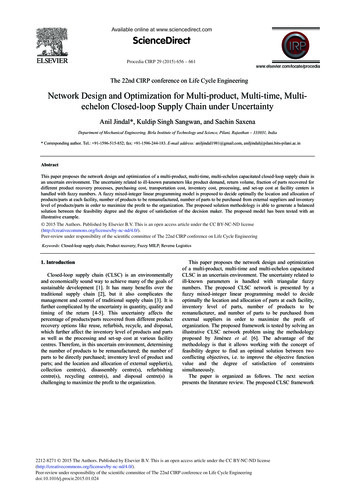
Multi-material stereolithographyRapid Prototyping JournalHuachao Mao et al.which leads to less reliability, higher cost and fewer materialchoices.Besides the multi-ink-jetting deposition method, multinozzle fusion deposition modeling (FDM) has also been widelyused because of its low cost. FDM uses multiple nozzles toextrude different filament materials and fuses them into acomponent with multiple materials. However, this multi-nozzleFDM process is applicable only to thermosensitive materials,e.g. acrylonitrile butadiene styrene and polylactic acid; itexcludes the commonly used photocurable polymers and thepolymer-derived materials (Bagheri and Jin, 2019). Also, theFDM-based 3D printers have limited fabrication speed andsurface quality (Armillotta, 2006; Nancharaiah et al., 2010). Avariant of the multi-nozzle FDM, known as multi syringesdeposition (Truby and Lewis, 2016), is a natural way to depositsoft materials, which finds a large variety of applications to printcomponents with soft matters.The aforementioned 3D printing processes share the samecharacteristics, i.e. they use nozzles with different sizes todeposit materials to the demanded area only, as summarized inFigure 1(a)–(c). The difference among these DOD processes ismainly how the material is deposited out of the nozzles.However, a user needs to make trade-offs among the materialdeposition rate, feature resolution and material choices. Incomparison, another widely used additive manufacturing (AM)method, stereolithography (SL), can cure photocurable resin atdesignated positions using controlled energy input, or “curingon-demand (COD).” The SL process has become anincreasingly used AM process since it was first introduced in1986 because of its characteristics such as high resolution, fastfabrication speed and extensive material choices (Hull, 1984;Pan et al., 2012; Pan et al., 2012; Tumbleston et al., 2015; Yanget al., 2017, 2019; Zhou et al., 2009). Unlike the DODmethods, COD methods deposit one material on a whole layerregardless of the designed shape, then selectively solidify thematerial in the area on-demand and, finally, clean theunsolidified liquid resin to prepare to switch to anothermaterial. This deposition and cleaning process is repeated foreach of the materials to be printed [Figure 1(d) and (e)].Figure 1 Schematic diagrams of representative multi-material 3Dprinting processes based on deposition-on-demand and curing-ondemandSuch a COD process, by depositing a whole layer of resin andcleaning the uncured material afterwards, presents differenttrade-offs among the material deposition rate, featureresolution and material choices. A critical challenge in theCOD multi-material SL process is to avoid mixing andcontamination between different liquid resins used in thefabrication process. Previous research on multi-material SLprocesses (Choi et al., 2010, 2011; Inamdar et al., 2006; Kimet al., 2010; Maruo et al., 2001; Wicker et al., 2004) mostlyfocused on the top-down-based projection, as shown inFigure 1(d). Because the printed part was entirely immersed inthe liquid resin, it was difficult to wash and clean the entireprinted part before switching the platform to another liquidresin vat. The whole-body cleaning process leads to a largeamount of material waste and requires a long washing time.In comparison, Zhou et al. (2013) developed a bottom-upbased multi-material SL process. They used two vats to containtwo different liquid resins, and before swapping the material,the uncured resin was cleaned using a brush and an ultrasoniccleaner. Ge et al. (2016) presented a similar multi-materialprinting process, in which two containers with different liquidresins were automatically exchanged to fabricate a part withtwo materials. Based on the bottom-up projection method,these SL processes need relatively shallower vats of liquid resin;hence, the printed part is immersed in the resin within a limiteddepth [Figure 1(f)]. Consequently, the uncured resin to becleaned was significantly reduced to only a few millimeters.Some recent work used dynamic fluidic control of multipleliquid photopolymers for micro-SL (Han, 2019). Regardless, itstill requires significant effort and a long time to clean theuncured resin. How to make the coated resin significantlyshallower (e.g. in the range of 100 m m) so a more efficient andeffective cleaning method can be devised is the main problemaddressed in this paper.To fill the gap in the multi-material SL process development,we herein present a novel 3D printing method based on a newCOD printhead, which reduces the coated resin to submillimeter level, which is comparable with the layer thickness.The new printhead uses a method of “coating, curing, cleaningand post-curing” (C3P). The core idea of the C3P method is toclean the non-cured material right after selective curing.Specifically, the liquid resin layer is uniformly coated and thenselectively photocured using the sliced mask image patternscomputed based on the input 3D model. Afterward, the noncured liquid resin is immediately cleaned up using a vacuum,and any residual resin is further photocured to avoid anypotential contamination with other materials. The developedC3P process can enable multi-material printing capability withmore material choices and achieve desired manufacturingcharacteristics such as high feature resolution, fast fabricationspeed and low machine cost. In Table 1, we compare ourmethods with other aforementioned multi-material 3D printingmethods. The proposed C3P method has a lower viscosityrequirement and is much less expensive than the droplet-ondemand method. Note the speed of “multi nozzles FDM” and“multi syringes extrusion” is dominated by the XY translationand extrusion speed, which is much slower than the maskimage-projection-based photocuring. Other COD methods canalso cure a whole layer; however, they require a long time toclean uncured liquid resin, which is addressed in the paper.
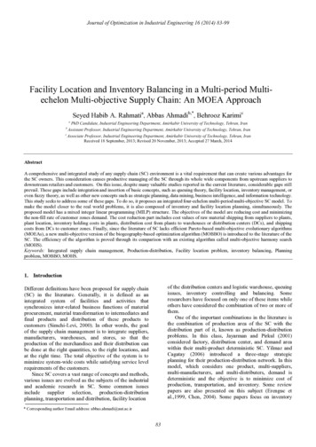
Multi-material stereolithographyRapid Prototyping JournalHuachao Mao et al.Table 1 Comparison of our method with other multi-material 3D printing ial viscosityCostReferenceInk-jettingMulti-nozzles FDMMulti-syringes extrusionTop-down SLBottom-up SLOur methodDODDODDODCODCODCOD14 m m100–200 m m20–200 m m 30 m m 47 m m30 m mFastSlowSlowSlowSlowMediumPhoto-curable resinThermo-plasticGel-like materialPhoto-curable resinPhoto-curable resinPhoto-curable resin 100 cp Sitthi-Amorn et al. (2015)Khalil et al. (2005)Truby and Lewis (2016)Choi et al. (2011)Zhou et al. (2013)This paper–– 1,000 cp 1,000 cp 1,000 cpNotes: “DOD” means deposition-on-demand, and “COD” indicates curing-on-demand. The “cost” reflects the key components’ cost in the correspondingprocess. The method “Ink jetting” refers to Stratasys J750. The resolution of “DOD” is determined by the nozzle size, whereas the resolution of “COD” isdetermined by the pixel size of the projection imageThe rest of this paper is organized as follows. Section 2describes the multi-material SL printing process and the relatedprinthead design. Methods to represent a component withmultiple materials are discussed in Section 3. Section 4experimentally characterizes the vacuum cleaning parametersand performance. Various fabrication results are shown inSection 5. Finally, Section 6 concludes the paper with futurework.Figure 2 Schematic diagrams and prototype of the multi-materialstereolithography process2. Principle of the C3P-based multi-materialstereolithography processIn this section, we present the principle and a relatedprototype of the proposed multi-material SL process. Asmentioned above, the main idea of the C3P process is toeffectively clean the non-cured resin right after the selectivephotocuring. A well-designed printhead is critical toincreasing printing efficiency, enhancing resin cleaningperformance and eliminating contamination betweendifferent materials.2.1 Process overviewA COD approach was developed in our study to address multimaterial coating, resin cleaning and eliminating potentialmaterial contamination. Figure 2(a) gives a schematic diagramof the printing system with multiple printheads. The detaileddesign of the printhead to fulfill the C3P process will bediscussed in Section 2.2. Unlike the DOD method, a wholeliquid resin layer is coated in C3P regardless of the layer’sdesigned shape. After the resin is coated, the printhead movestoward the curing section, as shown in Figure 2(a). A digitalmicromirror device (DMD) was used to project a 2D image tothe newly coated resin area and selectively cure a thin layer ofthe resin into the 2D sliced shape. Afterward, the uncuredliquid resin will be removed using a vacuum cleaning approach.After the uncured resin is cleaned, the printhead moves furthertoward the right, and a strong ultraviolet (UV) light post-curesany liquid residue on the part surface before the next printheadmoves in. Through the “coating, curing, cleaning and postcuring” process, one material can be successfully depositedonto the printed object mounted on the platform with thedesigned shape.After the first printhead finishes its C3P process, a secondprinthead moves toward the right to start the next C3Pprocess and add the second type of material to the samelayer [Figure 2(a)]. When all the printheads finish the C3Pprinting process of the layer, the printed layer was depositedwith multiple materials in controlled shapes. The platformwill raise a layer thickness. This procedure will be repeatedlayer-by-layer to create a 3D object with designed materialdepositions (refer to a video in the supplementary material).The developed prototype of the multi-material SL printer isshown in Figure 2(b). The pipes shown in the figure wereconnected to pumps and a vacuum device, which can coat andclean the resin, respectively. Figure 2(c) displays a prototype ofan assembly of four printheads, which can support the 3Dprinting with four different materials. The rightmost threeprintheads in Figure 2(c) were used to print an object with red,blue and green resins, whereas the very left printhead was usedto print a transparent supporting material. The fabricationprocess of one single layer with the red, blue and green resins isillustrated in Figure 2(d). The accordingly printed object is alsoshown in Figure 2(d) (right).
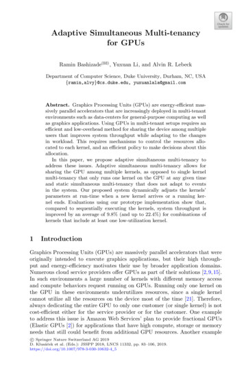
Multi-material stereolithographyRapid Prototyping JournalHuachao Mao et al.The proposed COD approach has several advantages overthe mask-image-projection-based additive manufacturingprocess described in our previous work (Zhou et al., 2013),which requires several containers with different types of liquidresins. The thorough cleaning of the fabricated parts betweendifferent resin tanks is time-consuming and challengingbecause a large amount of residual resin is left in each container(Zhou et al., 2013). In comparison, the C3P process in thiswork uses the controlled coating of a small amount of resin, sothe material cleaning is more effective and more manageable.Besides, a post-cure procedure after the cleaning step ensuresno material contamination between different printheads.2.2 A Compact printhead with coating, curing, cleaningand post-curingThe core idea of the developed multi-material SL process is toclean a small amount of uncured resin right after selectivelycuring the desired pattern, and the related printing processwould enable a compact printhead design. Consequently, asingle linear stage can be used to transport multiple printheadsefficiently during the printing process.Figure 3 shows one designed printhead to fulfill thepresented C3P process. The printhead has a flat top, which isdivided into four sections – a coating section, a curing section, avacuum-cleaning section and a post-curing section. Ourprinthead’s design goal is to pump as little resin as possible butstill sufficient to recoat the whole layer with a given layerthickness (e.g. 50 or 100 m m). Another design goal is to cleanout as much uncured resin as possible right after the layer isselectively photocured.Figure 3 Schematic diagram of a printhead (c) that fulfills the coating,curing, cleaning and post-curing (C3P) processTo ensure the printheads have a flat top surface aligned within alayer thickness, we fabricated the four printheads using a wholetransparent acrylic sheet with designed slots to pump andvacuum resin. The flat top surface and all the slots of the fourprintheads were machined together. Hence, the printheads canbe directly slid back and forth to swap the deposited resinwithout the time-consuming move-up-and-down transition(Zhou et al., 2013). The sliding of the printheads also reducesthe separation force using the shear force to separate the curedresin from the projection surface, which is smaller than thedirect pulling-up force (Pan et al., 2012; Zhou et al., 2013).Notice only the printheads are moved horizontally. The relativeposition of the projection system and the 3D-printed part arenot moved during the sliding process. Hence, the photocuringaccuracy of different materials in the layer will not be affectedby the switching of resins. Such a linearly moving printheaddesign enables us to coat the 3D-printed part with liquid resinas shallow as a single-layer thickness. We now discuss thedetails of these four sections as follows.2.2.1 CoatingThe ideal coating thickness of liquid resin is precisely equal tothe fabrication layer thickness (usually between 10 and250 m m). To achieve this design goal, we develop a novelcoating mechanism based on liquid resin’s surface tension. InFigure 3(b), a coating screen with designed small holes wasused as the coating section’s top surface. Because of the liquid’ssurface tension, the material permeates through the small holeswhen the liquid pressure reaches a certain level. When theplatform passes through the mesh screen from the above,the permeated liquid resin will be coated on the bottom of thepreviously printed layers and between the gaps. The layerthickness is controlled precisely by the linear Z stage, not by theamount of permeated liquid resin from the mesh screen. Bycontrolling the pump pressure (by adjusting the speed of astepper motor for the pump), we ensured around 0.3–0.5 mmresin permeated through the mesh screen that was then coatedon the previously built layers with a set layer thickness (e.g. 50or 100 m m). The permeated material height is determined bythe surface tension, hole size and liquid resin pressure.Increasing the fluid pressure will increase the permeated resinheight [Figure 3(b3)]. In our designed printhead, the pressurecan be dynamically controlled by a pump so that the pumpsettings can adjust the permeated resin height. Therefore, theprinthead can control the volume of the coated material, andonly a small amount of liquid resin will be coated and used inthe curing section. The extra resin will flow into the designedchannels between the coating and curing sections [shown as theblack area in Figure 3(c)] and suck back to the printhead’s resinreservoir.2.2.2 CuringAfter the platform or the previously built layers (includingdesigned supports) are coated with liquid resin slightly higherthan the layer thickness, the printhead moves to the curingsection and stops there during the curing process. A maskedimage is then projected upwards through a transparent glasswith a coated non-sticky film to the curing section. The coatedliquid resin will be photocured according to the projectedimage pattern. Hence, this photocuring can fabricate thedesired shape before the platform moves to the next section.
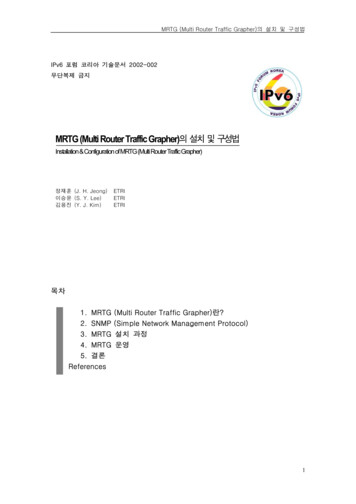
Multi-material stereolithographyRapid Prototyping JournalHuachao Mao et al.We used a DMD-based light system to generate the maskimage. The DMD contains an array of micromirrors, and eachmicromirror can be individually switched ON/OFF. Differentcombinations of the mirrors’ ON/OFF states generated themask images to allow controlled light to pass through a lensgroup and eventually generated planned projection images on afocusing plane. These focused mask images were used tophotocure the coated liquid resin.A non-sticky film-like polydimethylsiloxane (PDMS) orTeflon film was applied on the curing section’s top surface toensure the newly cured layer can be detached from theprinthead and firmly attached to the previously built layers(Chen et al., 2011). Also, because of this non-sticky film’sthickness, the curing section’s top surface is 100 m m higherthan those of the other sections. This height difference ensuresonly the curing section’s top surface directly contacts the builtlayer after the photocuring process. Other sections’ top surfacewill not directly contact the printed layers during theprintheads’ linear movement.2.2.3 CleaningBecause the printed object may have delicate features, anycontact of the photocured layers with the printheads maydestroy the newly printed features. A non-contact cleaningapproach using a vacuum pump was devised in our study. Inthe implementation, the “cleaning section” was connected witha vacuum pump via a sealing pipe [Figure 4(a)]. The vacuumpump provides a negative pressure compared to theatmospheric pressure on the section’s top surface.Consequently, this negative pressure sucks the uncured liquidresin from the photocured layers.As shown in Figure 4(a), several small slots of different sizeswere designed on the vacuum-cleaning section’s top surface.These small slots were designed to increase the vacuum force.Figure 4(b) shows the detailed design of such small slots. Thewidth of the small slots ranged from 50 m m to 1 mm. Duringthe fabrication, the first vacuum slot with a larger size suckedout most of the uncured liquid resin, and then the second andthe last slots will further clean the uncured material. Thenumber of such slots could be 1, 2 or more. In our tests,additional slots of more than five slots had little effect on furtherremoving the residual material. After the cured layers passedthrough the vacuum-cleaning section, most of the uncuredmaterial was removed, and only less than 10% residual materialwas left. The amount of the residual liquid resin on the printedFigure 4 Vacuum-cleaning section designlayers is related to the printhead’s moving speed; the gapbetween the vacuum slots and the printed layers; and thevacuum pressure. The cleaning performance of differentparameters will be discussed in Section 4.Figure 4(a) shows the uncured liquid resin is vacuumed intoa stopper. Instead of being wasted, the collected liquid resinwas recycled into the material reservoir when the stopper’smaterial reached a certain amount. In each printhead, a recyclepump was added to pump the liquid resin in the stopper intothe material reservoir. Because a majority of the coated resin isrecycled in the printing process, the C3P-based multi-materialSL process has much less material waste. It also requiressignificantly less material swapping time than the cleaningmethods of using solvents such as ethanol to wash the uncuredliquid resin (Choi et al., 2010; Zhou et al., 2013).2.2.4 Post-curingA small amount of residual liquid resin may still exist after thevacuum-cleaning section. To ensure no contaminationbetween different liquid resins when switching to anotherprinthead, we added a post-curing section in the final portion ofthe printhead. Any residual liquid resin left on the printedlayers will be fully cured before it contacts other printheadswith different types of resins. This post-curing step can usevarious kinds of light sources, such as a digital light processing(DLP) projector, a few strong light-emitting diodes and a laserscanning module (Mao et al., 2016). In our implementation ofthe post-curing section, we reused the DLP light source thatwas used in the curing section. The post-curing sectionconducts a second light exposure to the printed layers. Theexposure of the residual liquid resin may lead to an additional10% cured materials (e.g. instead of 100 m m layer thickness,the printed layer will have 110 m m thickness). However,photocuring residual liquid after vacuum-cleaning wouldensure no resin contamination between different printheads inthe layer-by-layer fabrication process.3. Data representation and process softwareThis section discusses the data representation and processsoftware developed for the multi-material SL process. We firstpresent the representation method to define a 3D multimaterial model and, accordingly, the flow chart to fabricatesuch a digital model.3.1 Methods of representing a multi-material modelThe input of the developed multi-material SL process is adigital computer-aided design (CAD) model. However, unlikea 3D printing process using a single material, some novelrepresentation methods are required to define a 3D object withmultiple material compositions (Leung et al., 2019a, 2019b;Xu et al., 2015). A valid multi-material representation methodshould uniquely define the material information at any positionin the 3D CAD model.The proposed C3P process requires one mask image for eachmaterial at each layer. For this purpose, we used two differentmodel representations in our study:1 Separate standard triangle languages (STLs) filesAn intuitive representation method is to use different STLmodels to represent each material and then plan the maskimage for each printhead accordingly. Each STL model
Multi-material stereolithographyRapid Prototyping JournalHuachao Mao et al.will be individually sliced into a set of mask images for thelayer-based fabrication process (Huang et al., 2013; Zhouet al., 2009).2 Color imagesOur process can also accept a series of color images. Theprinting process regards each color image as one layer.Given the thickness of each image and the actual size ofeach pixel, the printer can map the color image to abuilding range. Four channels of the material informationcan be extracted from one image’s RGB and alphachannels. And each channel information (i.e. red, greenand blue) was used to define the mask image for itscorresponding printhead.An example of how a model was represented in the multimaterial SL process is shown in Figure 5. For a part definedwith three STL models [Figure 5(a)], we first sliced each STLmodel and reassembled each STL’s mask images into a singlecolor image file (BMP) at each layer. These BMP imagesrepresented the material distributions and were used togenerate the mask images for each printhead. Besides slicingfrom the STL models, these digital images can also be directlycreated using any design packages.3.2 Software system and process controlWe developed a software system using C11 to control theC3P-based multi-material SL process. The software systemcontrols all the devices, including the light engine (a projectorwith a DMD chip), a vacuum device, four liquid pumps and athree-axis linear stage. The interface of the developed softwareFigure 5 An illustrative pipeline of slicing a three-material model tofabricate a multi-material objectFigure 6 System control of the C3P-based multi-material SL processsystem is shown in Figure 6(a), and the control logic of thesystem illustrated as a flow chart diagram is given in Figure 6(b). On the left side of the diagram, a set of the preparationprocesses was performed before the actual printing of a 3Dobject, including configuring the 3D printing system,initializing the platform position and turning on the vacuumand coating pumps. Afterward, the software system executes aprinting loop to fabricate the 3D object layer-by-layer, as shownin the middle of Figure 6(b), until all the layers have beenprinted. The right portion of the flow chart diagram shows thedetailed C3P processes for each printhead. And this sub-loopends when all the printheads finish the C3P process.4. Vacuum cleaning characterization and testingThe vacuum-cleaning section in the printhead recycles most ofunused liquid resin and determines the Z resolution of thedeveloped C3P-based multi-material SL process. As a criticalstep in C3P, various experiments were conducted to enhanceits cleaning performance.A vacuum pump was connected to the printheads’ vacuumcleaning sections to remove the uncured liquid resin[Figure 4(a)]. Our experiments showed that the cleaningperformance was affected by the relative moving speed betweenthe platform and the printhead; the gap between the printheadand the printed part; and the negative pressure value. Figure 7(d) and 7(f) presents our experimental results on how theseparameters affect cleaning performance. A test part withsurface area A was used in our study [Figure 7(c)]. Thecleaning performance was measured by the thickness ofthe residual resin left on the printed part. First, we measuredthe weight of a clean tissue paper (WT) using an analyticalbalance whose resolution is 1 mg. After printing a layer usingthe printhead, we thoroughly cleaned the printed part using thetissue paper to collect all the residual resin. We then measuredthe tissue paper to get its weight WR. Hence, the weight of theresidual resin can be calculated as W WR WT, and the totalvolume of the residual resin can be calculated based on theresin density r . Finally, the thickness of the residual resin ish ¼ W ð r AÞ.When the vacuum-cleaning section with opening slots movesclose to the built layers with uncured resin, the neighboring airwill be sucked into the opening slots because of the pressure
Multi-material stereolithographyRapid Prototyping JournalHuachao Mao et al.Fi
the post-curing section, we reused the DLP light source that was used in the curing section. The post-curing section conducts a second light exposure to the printed layers. The exposure of the residual liquid resin may lead to an additional 10% cured materials (e.g. instead of 100mm layer thickness,