Transcription
Operation ManualBently Nevada Asset Condition Monitoring330400 and 330425 AccelerometerPart Number 127088-01Rev. H (08/07)
330400 and 330425 Accelerometer Operation ManualCopyright 1996. Bently Nevada LLC.All rights reserved.The information contained in this document is subject to change without notice.The following are trademarks of General Electric Company in the United States and othercountries:ACM, Actionable Information, Actionable Information to the Right People at the RightTime, ADRE, Asset Condition Management, Asset Condition Monitoring, Bently ALIGN,Bently BALANCE, Bently DOCUVIEW, Bently LUBE, Bently Nevada, Bently PERFORMANCE,Bently RELIABILITY, CableLoc, ClickLoc, Data Manager, Decision Support, DemoNet,Dynamic Data Manager, Engineer Assist, FieldMonitor, flexiTIM, FluidLoc, Helping YouProtect and Manage All Your Machinery, HydroScan, HydroView, Key , Keyphasor,Machine Condition Manager 2000, MachineLibrary, Machine Manager, MicroPROX, MoveData, Not People, Move Information, Not Data, NSv, Prime Spike, PROXPAC, Proximitor,REBAM, RuleDesk, SE, Seismoprobe, Smart Monitor, Snapshot, System 1, SystemExtender, TDXnet, TDIXconnX, The Plant Asset Management Company, TipLoc, TorXimitor,Transient Data Manager, Trendmaster, TrimLoc, Velomitorii
Contact InformationThe following ways of contacting Bently Nevada are provided for those times when youcannot contact your local representative:Mailing AddressTelephoneFaxInternet1631 Bently Parkway SouthMinden, Nevada USA www.ge-energy.com/bentlyiii
330400 and 330425 Accelerometer Operation ManualAdditional InformationNotice:This manual does not contain all the information required to operate and maintainthe product. Refer to the following manuals for other required information.3300/25 Dual Accelerometer Input Monitor (Peak) Maintenance Manual(Part Number 80181-01)3300/26 Dual Accelerometer Input Monitor (RMS) Maintenance Manual(Part Number 86800-01)2201 Operation and Maintenance Manual (Part Number 100875-01)3500/42 Proximitor/Seismic Monitor Module Operation and MaintenanceManual (Part Number 129773-01)Product Disposal StatementCustomers and third parties, who are not member states of the European Union, who arein control of the product at the end of its life or at the end of its use, are solelyresponsible for the proper disposal of the product. No person, firm, corporation,association or agency that is in control of product shall dispose of it in a manner that isin violation of any applicable federal, state, local or international law. Bently Nevada LLCis not responsible for the disposal of the product at the end of its life or at the end of itsuse.iv
Contents1.Operating Information .11.11.21.32.Application .1Principle of Operation .1Compatible Monitoring Systems .2Installation .42.1Receiving Inspection .42.2Installing the Accelerometer .42.2.1 Positioning .42.2.2 Mounting .42.2.3 Routing Cable.52.2.4 Routing Conduit .52.2.5 Routing Armored Cable.52.2.6 Sealing the Interconnect Cable .62.3Power and Signal Connections .62.3.1 3300 MONITORING SYSTEM.62.3.2 2201 MONITORING SYSTEM.62.3.3 3500 MONITORING SYSTEM.72.3.4 EXTERNAL POWER SUPPLY .73.Maintenance .123.13.24.Performance Test Procedure .12Polarity Test Procedure.12Field Testing and Troubleshooting .144.14.25.Fault Indication #1 Cause/Solution.14Fault Indication #2 5.2.25.2.35.2.45.2.55.35.45.5330400 Accelerometer.16Electrical .16330425 Accelerometer.17Electrical .17Environmental for the 330400 and the 330425 Accelerometer .18Mechanical for the 330400 and 330425 Accelerometer .18Interconnect Cable for the 330400 and 330425 Accelerometer.18Standard Armored Interconnect Cable: .19Mechanical Outline .21330400 Accelerometer Frequency Response.22330425 Accelerometer Frequency Response.23v
330400 and 330425 Accelerometer Operation Manual6.Accessories and Spare Parts 400 Accelerometer Options. 24330400 Accelerometer. 24Mounting Stud: Option A . 24Agency Approvals: Option B . 24330425 Accelerometer Options. 24330425 Accelerometer. 24Mounting Stud C Option A . 24Agency Approvals C Option B . 25Transducer Housing. 25Interconnect Cable Options. 25
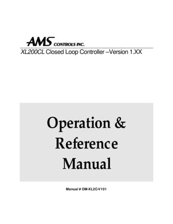
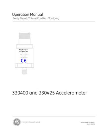
Section 1 - Operating Information1. Operating InformationThis section contains information that will help you prepare for the installation ofthe Accelerometer Systems. General information for typical applications,principles of operation, and monitoring compatibility of the Accelerometers arepresented in this section.1.1 ApplicationAccelerometers are very effective when used for the measurement of highfrequency vibrations. Supplemental high frequency casing measurements aretypically required for measuring gear mesh and blade pass frequencies. Section2 explains the proper installation of the Accelerometers.Application Advisory: If casing acceleration measurements are beingmade for the overall protection of a machine, thought should be given tothe usefulness of the measurement for each application. Most commonmachine malfunctions, such as unbalance, misalignment, etc., occur onthe rotor and originate as an increase or a change in rotor vibration. Forany casing measurement alone to be effective for overall machineprotection, a significant amount of rotor vibration must be faithfullytransmitted to the machine casing or mounting location of thetransducer. In addition, care should be exercised in the physicalinstallation of the acceleration transducer on the bearing housing ormachine casing. Improper installation may result in a decrease of thetransducer amplitude and frequency response and the generation offalse signals that do not represent vibration on that particular machine.1.2 Principle of OperationThe Accelerometer is made up of a piezoelectric shear-mode element andelectronics. When subjected to machinery vibration, this mass/spring systemexerts a force on the piezoelectric ceramic, which generates a charge proportionalto that force. The electronics converts the charge to a voltage that can be sent toa Bently Nevada monitoring system.The 330400 and 330425 Accelerometers are designed to monitor vibrationfrequencies ranging from 10 Hz to 15 kHz. The calibrated scale factor andmaximum acceleration for the Accelerometers are shown in Table 1.Table 1-1.TransducerScale FactorModel(mV/g 5%)33040033042510025MaximumAcceleration5075The 330400 and 330425 Accelerometers are three wire transducers whichrequire external power supplies. The power supply voltage is -24 Vdc. Asimplified schematic block diagram of the 330400 and 330425 Accelerometerappears in Figure 1-1.1
330400 and 330425 Accelerometer Operation ManualThe internal circuitry of the 330400 and 330425 accelerometers automaticallysets the output dc bias when power is supplied. The dc bias and ac signalappears across pin "A" and "C”.Figure 1-1 Schematic Block Diagram1.3 Compatible Monitoring SystemsCompatible Bently Nevada monitoring systems can power the 330400 and330425 Accelerometer without additional external circuitry.The flexibility of the 3300 Dual Accelerometer Monitor, the 2201 Monitor and3500/42 (or 3500/42M) Monitor makes them ideally suited for use with the 330400and 330425 Accelerometers. The Alert and Danger setpoints and filtering can beadjusted to isolate, eliminate, or emphasize specific vibration frequencies. Themonitor can also be configured to integrate each channel to provide output interms of velocity. OK circuitry continuously monitors field wiring for open andshort circuits and for Accelerometer malfunctions.The monitoring systems and full-scale range options that are compatible with the330400 and 330425 Accelerometers are shown in Table 1-1 and Table 1-2.2
Section 1 - Operating InformationTable 1-2. Compatible Full-Scale Range Options for the 330400 AccelMonitoring SystemCompatible Full-scale with No IntegrationpkrmsFull-Scale with Integrationpkrms3300/25Compatible with all full-scale range optionsCompatible with all full-scalerange options3300/260 to 5 g0 to 2 g0 to 10 g20 to 20 m/s0 to 50 m/s20 to 100 m/s222010 to 2 g0 to 5 g0 to 10 g20 to 20 m/s0 to 50 m/s20 to 100 m/s23500/42or3500/42M0 to 2 g0 to 5 g0 to 10 g0 to 20 m/s20 to 50 m/s20 to 100 m/s20 to 1 in/s0 to 2 in/s0 to 25 mm/s0 to 50 mm/s0 to 1 in/s0 to 2 in/s0 to 25 mm/s0 to 50 mm/s0 to 1 in/s0 to 2 in/s0 to 25 mm/s0 to 50 mm/sSee manual part number 129773-01 for moredetailsTable 1-3. Compatible Full-scale Range Options for the 330425 AccelMonitoring SystemCompatible Full-Scale with No Integrationpkrms3300/260 to 20 g0 to 25 g0 to 40 g0 to 50 g20 to 200 m/s0 to 250 m/s20 to 400 m/s
When subjected to machinery vibration, this mass/spring system exerts a force on the piezoelectric ceramic, which generates a charge proportional to that force. The electronics converts the charge to a voltage that can be sent to a Bently Nevada monitoring system. The 330400 and 330425 Accelerometers are designed to monitor vibration frequencies ranging from 10 Hz to 15 kHz. The