Transcription
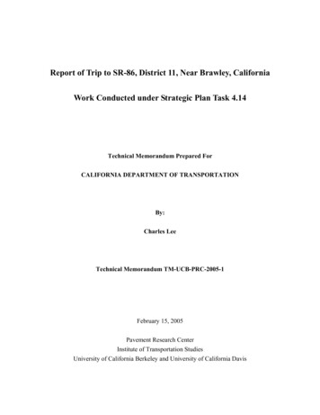
Report of Trip to SR-86, District 11, Near Brawley, CaliforniaWork Conducted under Strategic Plan Task 4.14Technical Memorandum Prepared ForCALIFORNIA DEPARTMENT OF TRANSPORTATIONBy:Charles LeeTechnical Memorandum TM-UCB-PRC-2005-1February 15, 2005Pavement Research CenterInstitute of Transportation StudiesUniversity of California Berkeley and University of California Davis
INTRODUCTIONA rubberized asphalt chip seal project on SR-86 in District 11 exhibited flushing andrutting shortly after construction. These defects occurred within the 1-year performance warrantyperiod specified in Section 10-1.22 of the Special Provisions of Contract No. 11-241104. Resultsof California Test 342 performed by Caltrans have confirmed that the coefficient of friction for theflushing segment were less than 0.30, which is less than the minimum required by contract. Thecontractor refuses to perform the specified repair at contractor’s expense, saying they followedCaltrans specifications and, therefore, are not responsible for a defect due to an “inadequatespecification” (given the project condition). On Dec. 17, 2004, Caltrans HeadquartersMaintenance and the Pavement Research Center agreed on a study to address the following fourobjectives:1. Investigate if the causes of failure of the asphalt rubber chip seal project in District 11can be determined.·Determine compliance with prescriptive specifications and relate prescriptivespecifications to failure or success.·Collect test and construction records and investigate if the cause of failure can bedetermined.
·No lab testing is required unless it is apparent that lab testing will help determinecauses of failure. Lab testing will be subject to costs and scheduling constraints,availability of resources, and further discussion. Core samples collected to performlab testing by Caltrans District 11.2. Determine the effectiveness of the materials and workmanship warranty on this project.·Critique the concept of combining prescriptive specifications and performancecriteria and provide a preliminary statement about the efficacy of combining thesecriteria.3. Evaluate and critique the planned 2-year performance warranty if the cause of ruttingand flushing is identified.4. Determine whether the Department should move toward performance warrantiesinstead of materials and workmanship based on discussions with various experts andavailable information.Note: Gerry Huber (Heritage Research Group) and Steven Krebs (WI DOT) haveagreed to provide advice. Other sources for advice suggested by Shakir have not yetresponded at the time of this writing.
Project HistoryThe following project history was made available in the Rubber Chip Seal – Route 86, EA11 – 241101 report provided by Ron Jones, Caltrans HQ Maintenance: July 2002: First inspection for being considered a warranty pilot project candidate. May 2003: Second inspection for being considered a warranty pilot project candidate. Sept 2003: Preventative maintenance work performed (rubber AC chipseal) based on1-year materials and workmanship performance warranty. Mar 2004: Post-construction review of the 6-mile section conducted; signs of bleedingwere evident. Caltrans decides to wait after summer to see how temperature mightfurther affect the pavement. Sept 2004: Re-evaluation. Severe bleeding and rutting in #2 lane NB. Note: by thistime, the Resident Engineer has already issued a Construction Change Order (CCO) tofix a part of the section. Contractor blames bad design from Caltrans as cause of thepavement distress and is not willing to fix the defect at contractor’s cost. Caltrans hasagreed to pay for the overlay rip and replacement, which will be carried out in early2005 (unconfirmed) and the contractor has agreed to provide a 2-year performancewarranty.
Warranty Pilot Project Selection ProcessThe Warranty Review Committee reviews the 4-year performance history data (percentcracked, percent patched, IRI, etc.) of the proposed road section then makes a condition survey toensure the section is structurally sound. One or more 1-year preventative warranty pilot projectsare then selected and actions taken at the first sign of any minor distress on dry pavement.CORING TRIP SUMMARYIn an attempt to address Objective 1 (presented in the Introduction), a coring session wasundertaken by Caltrans on January 20, 2005. Basic information from the trip is presented inTable 1.Table 1Details of PRC Coring EffortPavement Research Center – University of CaliforniaDate of trip01/20/2005LocationDistrict 11Imperial CountyState Route 86PM 37.3-43.4, NorthboundWeatherSunny/clear sky70–76ºFCore Diameter4.5 in.Pavement TypeACCore MethodWet
A total of 35 wet cores were collected at 9 different locations. The thickness of the RAClayer is measured based on the average of 4 measurements around the perimeter of each cylinder.No chip seal sample was available, however Shawn Rizzutto (District 11 CE) indicated that chipseal binder samples are available. Also, because the cores were 4.5 in. diameter instead of the 6-in.diameter originally calculated by the Pavement Research Center as adequate to obtain enoughsample quantity for the “finger-print” binder testing, Shawn Rizzuto offered to perform thescraping and collect the chip seal sample for the PRC before the contractor performs the repair.The numbering system for the cores is shown in Table 2 (refer to Figure 1).The core location numbering system was developed by District 11 personnel with respectto the station numbering system that was setup during the RAC chip seal construction. The stationnumber at the beginning of construction starts with Station 609 07 (Postmile 37.3) and continuesto Station 705 19 (Postmile 43.3) at the end of construction section. The station numbers aremarked in 40-m intervals, e.g. 610 40, 610 80, 611 20, etc. Figure 2 shows a map of the sitelocation; Figure 3 presents the project plans.The 9 stations at which cores were extracted were: 610 40, 616 21, 616 37, 617 60,618 00, 652 40, 654 00, 688 40, 696 00 (from south to north). Station 688 40 is located in thesecond 0.5-mile section south of the Immigration and Naturalization Service (INS) station where aCCO was issued to apply a layer of RAC chip seal over the OGAC. The last station, 696 00, is
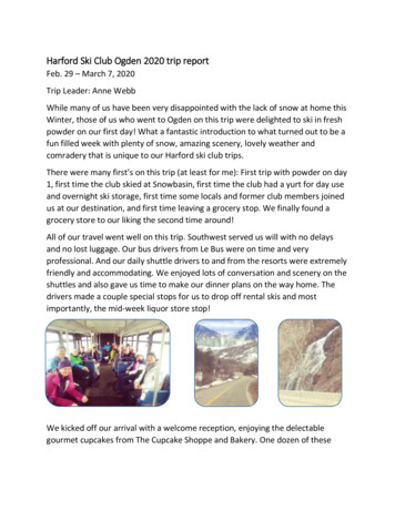
Table 2Core Location Numbering SystemCore LabelLocation (Shown in Figure 1)Location 1Left shoulderLocation 2#1 lane, left wheelpathLocation 3#1 lane, between wheelpathsLocation 4Lane dividing lineLocation 5#2 lane, left wheelpathLocation 6#2 lane, between wheelpathsLocation 7#2 lane, right wheelpathLocation 8Right shoulderFigure 1. Core locations on section.
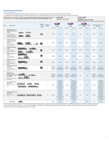
Figure 2. Site location.11MapQuest.com, Inc. http://www.mapquest.com/directions/main.adp. Website accessed February, 2005.
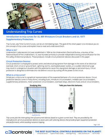
Figure 3. Site plan.
located in the half-mile section just south of the INS station where no RAC chip seal was applied,rather just a layer of OGAC was paved.Summary of FindingsIn short, flushing exists throughout the entire pavement section except for the 1-milesection south of the INS station. An OGAC layer was paved in this area because of braking and theextended duration of heavy loading near the INS inspection station. Figures 4-13 show that severeflushing starts at Station 606 (300 m ahead south of the beginning of construction according to theTitle and Location Map) and lasts all the way until the OGAC section (1 mi. south of the INSstation). Throughout the same section, wheelpath rutting ranges from 2 to 38 mm (measuredduring the first week of December 2004).Table 2Core MeasurementsChip Seal Thickness at Core Location, mmRut Depth in Wheelpath, mmStation23Left WheelpathRight Wheelpath610 4011104567910132214131423331215101838617 60121311616618 001010101116101191218654 00101210211688 4010101000616 21616 37652 401110111113* Rut depths were measured January 20, 2005.813
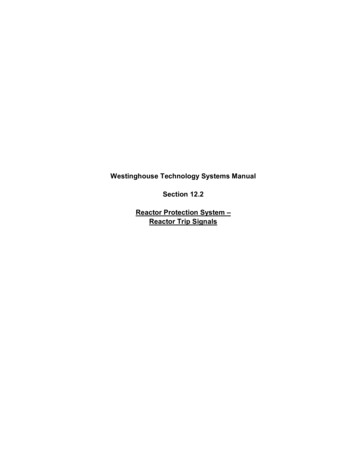
Figure 4. Station 606, facing south; RAC chip seal construction starts at this point.Figure 5. Station 606, facing north – RAC chip-sealed section starts here.
Figure 6. Station 608 (PM 37.3), facing north—flushing evident in #2 lane.Figure 7. Station 610 40, facing south—flushing evident in #2 lane.
Figure 8. Station 612, facing north—flushing evident in #2 lane.Figure 9. Station 616 37, facing south—note that #1 lane is clear of flushing and ruttingwhile #2 lane shows clear evidence of flushing and rutting.
Figure 10. Station 616 21, facing north—note rutting and flushing.Figure 11. Station 617 60, facing south—clear evidence of flushing in #2 lane.
Figure 12. Station 652 40, facing south—flushing evident in #2 lane.Figure 13. Station 688, facing south—OGAC RAC chip sealed #2 lane without evidence ofdistress.
Summary of FindingsThere is no apparent correlation of RAC chip seal thickness with the measured rut depth.The northbound roadway was built in the 1920’s (approximately). Some of the cores have as manyas 8 identifiable layers of AC. Hence, past maintenance treatment/rehabilitation should also beconsidered when evaluating possible causes of current distress.Current StatusThe contractor will not start the overlay and rip and replacement operation until the causeof the distress is identified and corrective actions are determined.Last updated during late January 2005, District 11 has not begun testing on the cores.District 11 said that the PRC can evaluate leftover cores after District 11 completes their tests. It iscurrently unknown which cores District 11 plans to test; consequently, the date for the PRC to pickup the cores is not set.Action Items Proposed:1. PRC to send personnel and truck to District 11 to bring back the cores when District 11identifies available cores.2. Caltrans District 11 to provide PRC with a copy of all historical workingdocumentation for this project.
APPENDIX A: DATA FOR THE CORES EXTRACTED JANUARY 20, 2005Station 610 40Core Location610 40 No. 2Overall Core Thickness258 mmChip Seal Thickness11 mmRut DepthLeft WheelpathRight WheelpathN/AN/ACore Location610 40 No. 3Thickness (1st layer beneath chip seal only)118 mmChip Seal Thickness10 mmRut DepthLeft WheelpathLeft WheelpathN/AN/A
Core Location610 40 No. 5Overall Core Thickness165 mmChip Seal Thickness9 mmRut DepthLeft WheelpathRight Wheelpath2 mm2 mmCore Location610 40 No. 6Thickness (1st layer beneath chip seal only)154 mmChip Seal Thickness10 mmRut DepthLeft WheelpathRight Wheelpath2 mm2 mm
Core Location610 40 No. 7Overall Core Thickness157 mmChip Seal Thickness13 mmRut DepthLeft WheelpathRight Wheelpath2 mm2 mmStation 616 21Core LocationStation 616 21, Location 5Overall Core Thickness199 mmChip Seal Thickness14 mmRut DepthLeft WheelpathRight Wheelpath23 mm33 mm
Core Location616 21, Location 6Overall Core Thickness211 mmChip Seal Thickness13 mmRut DepthLeft WheelpathRight Wheelpath23 mm33 mmCore Location616 21, Location 7Overall Core Thickness190 mmChip Seal Thickness14 mmRut DepthLeft WheelpathRight Wheelpath23 mm33 mm
Station 616 37Core LocationStation 616 37, Location 2Overall Core Thickness209 mmChip Seal Thickness11 mmRut DepthLeft WheelpathRight WheelpathN/AN/ACore LocationStation 616 37, Location 3Overall Core Thickness209 mmChip Seal Thickness11 mmRut DepthLeft WheelpathRight WheelpathN/AN/A
Core LocationStation 616 37, Location 4Overall Core Thickness211 mmChip Seal Thickness13 mmRut DepthLeft WheelpathRight Wheelpath18 mm38 mmCore LocationStation 616 37, Location 5Overall Core Thickness194 mmChip Seal Thickness12 mmRut DepthLeft WheelpathRight Wheelpath18 mm38 mm
Core LocationStation 616 37, Location 6Overall Core Thickness196 mmChip Seal Thickness15 mmRut DepthLeft WheelpathRight Wheelpath18 mm38 mmCore LocationStation 616 37, Location 7Overall Core Thickness170 mmChip Seal Thickness10 mmRut DepthLeft WheelpathRight Wheelpath18 mm38 mm
Image not availableCore LocationStation 616 37, Location 8Overall Core Thickness124 mmChip Seal Thickness13 mmRut DepthLeft WheelpathRight Wheelpath18 mm38 mmStation 617 60Core LocationStation 617 60, Location 5Overall Core Thickness206 mmChip Seal Thickness12 mmRut DepthLeft WheelpathRight Wheelpath6 mm16 mm
Core LocationStation 617 60, Location 6Overall Core Thickness215 mmChip Seal Thickness12 mmRut DepthLeft WheelpathRight Wheelpath6 mm16 mmCore LocationStation 617 60, Location 7Overall Core Thickness206 mmChip Seal Thickness11 mmRut DepthLeft WheelpathRight Wheelpath6 mm16 mm
Station 618 00Core LocationStation 618 00, Location 5Overall Core Thickness201 mmChip Seal Thickness10 mmRut DepthLeft WheelpathRight Wheelpath11 mm16 mmCore LocationStation 618 00, Location 6Overall Core Thickness207 mmChip Seal Thickness10 mmRut DepthLeft WheelpathRight Wheelpath11 mm16 mm
Core LocationStation 618 00, Location 7Overall Core Thickness202 mmChip Seal Thickness10 mmRut DepthLeft WheelpathRight Wheelpath11 mm16 mmStation 652 40Core LocationStation 652 40, Location 2Overall Core Thickness210 mmChip Seal Thickness10 mmRut DepthLeft WheelpathRight WheelpathN/AN/A
Core LocationStation 652 40, Location 3Overall Core Thickness217 mmChip Seal Thickness11 mmRut DepthLeft WheelpathRight WheelpathN/AN/ACore LocationStation 652 40, Location 5Overall Core Thickness198 mmChip Seal Thickness10 mmRut DepthLeft WheelpathRight Wheelpath12 mm18 mm
Core LocationStation 652 40, Location 6Overall Core Thickness216 mmChip Seal Thickness11 mmRut DepthLeft WheelpathRight Wheelpath12 mm18 mmCore LocationStation 652 40, Location 7Overall Core Thickness199 mmChip Seal Thickness9 mmRut DepthLeft WheelpathRight Wheelpath12 mm18 mm
Station 654 00Core LocationStation 654 00, Location 5Overall Core Thickness191 mmChip Seal Thickness10 mmRut DepthLeft WheelpathRight Wheelpath2 mm11 mmCore LocationStation 654 00, Location 6Overall Core Thickness206 mmChip Seal Thickness12 mmRut DepthLeft WheelpathRight Wheelpath2 mm11 mm
Core LocationStation 654 00, Location 7Overall Core Thickness204 mmChip Seal Thickness10 mmRut DepthLeft WheelpathRight Wheelpath2 mm11 mmStation 688 40Core LocationStation 688 40, Location 5Overall Core Thickness261 mmOG / Chip Seal Thickness28 mm / 10 mmRut DepthLeft WheelpathRight Wheelpath0 mm0 mm
Core LocationStation 688 40, Location 6Overall Core Thickness257 mmOG / Chip Seal Thickness27 mm / 10 mmRut DepthLeft WheelpathRight Wheelpath0 mm0 mmCore LocationStation 688 40, Location 7Overall Core Thickness250 mmOG / Chip Seal Thickness29 mm / 10 mmRut DepthLeft WheelpathRight Wheelpath0 mm0 mm
Station 696 00Core LocationStation 696 00, Location 5Overall Core Thickness324 mmOG Layer Thickness12 mmRut DepthLeft WheelpathRight WheelpathN/AN/ACore LocationStation 696 00, Location 6Overall Core Thickness335 mmOG Layer Thickness7 mmRut DepthLeft WheelpathRight WheelpathN/AN/A
Core LocationStation 696 00, Location 7Overall Core Thickness290 mmOG Layer Thickness17 mmRut DepthLeft WheelpathRight WheelpathN/AN/A
currently unknown which cores District 11 plans to te st; consequently, the date for the PRC to pick up the cores is not set. Action Items Proposed: 1. PRC to send personnel and truc k to District 11 to bring back the cores w hen District 11 identifies available cores. 2. Caltrans District 11 to provide PRC with a copy of all historical working