Transcription
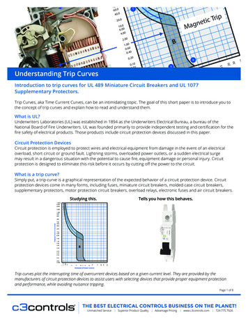
Understanding Trip CurvesIntroduction to trip curves for UL 489 Miniature Circuit Breakers and UL 1077UnderstandingTrip CurvesSupplementary Protectors.Trip Curves, aka Time Current Curves, can be an intimidating topic. The goal of this short paper is to introduce you tothe concept of trip curves and explain how to read and understand them.What is UL?Underwriters Laboratories (UL) was established in 1894 as the Underwriters Electrical Bureau, a bureau of theNational Board of Fire Underwriters. UL was founded primarily to provide independent testing and certification for thefire safety of electrical products. Those products include circuit protection devices discussed in this paper.Circuit Protection DevicesCircuit protection is employed to protect wires and electrical equipment from damage in the event of an electricaloverload, short circuit or ground fault. Lightning storms, overloaded power outlets, or a sudden electrical surgemay result in a dangerous situation with the potential to cause fire, equipment damage or personal injury. Circuitprotection is designed to eliminate this risk before it occurs by cutting off the power to the circuit.What is a trip curve?Simply put, a trip curve is a graphical representation of the expected behavior of a circuit protection device. Circuitprotection devices come in many forms, including fuses, miniature circuit breakers, molded case circuit breakers,supplementary protectors, motor protection circuit breakers, overload relays, electronic fuses and air circuit breakers.Studying this.Tells you how this behaves.Trip curves plot the interrupting time of overcurrent devices based on a given current level. They are provided by themanufacturers of circuit protection devices to assist users with selecting devices that provide proper equipment protectionand performance, while avoiding nuisance tripping.Page 1 of 8THE BEST ELECTRICAL CONTROLS BUSINESS ON THE PLANET!Unmatched Service Superior Product Quality Advantage Pricing www.c3controls.com 724.775.7926
Different Types of Trip CurvesMost Common Trip CurvesB CurveC CurveD Curve3-5X Instantaneous Tripping5-10X Instantaneous Tripping10-20X Instantaneous TrippingIntended for resistive circuitsIntended for circuits with mediuminductive loadsIntended for use in highly inductiveand capacitive loadsEx: Lighting, Control Circuits,Wire and CableEx: Control Panels, Lighting, CoilsEx: Motors, TransformersUL 1077UL 489, UL 1077UL 489, UL 1077S CurveZ CurveK Curve13-17X Instantaneous Tripping2-3X Instantaneous Tripping10-14X Instantaneous TrippingIntended for use in highlyinductive loadsIntended for use in circuits that require a very low short circuittrip settingIntended for use in highlyinductive loadsExamples: Control Circuits,Light FilamentsExamples: Semiconductors andControl CircuitsExamples: motors andTransformersUL 489, UL 1077UL 489, UL 1077UL 489, UL 1077More Specialized Trip CurvesWhy do we need different trip curves?Circuit breakers must trip quick enough to avoid equipment or wiring failure, but not so fast as to give false, ornuisance trips.To avoid nuisance trips, circuit breakers need to be sized appropriately to compensate for inrush current. NEMAdefines instantaneous peak inrush as the momentary current transient that occurs immediately (within half an AC cycle)after contact closure.Inrush current is what causes the lights to dim in a house when a motor, such as that on a clothes dryer or vacuumcleaner starts up.Figure 2 (below) is an example of the inrush current for an AC motor.Page 2 of 8
As the graph shows, the inrush current caused by switching the motor on is 30A. It is much higher than the operating,or steady state current. The inrush current peaks, then begins to decay as the motor spins up.We need different trip curves in order to balance the right amount of overcurrent protection against optimal machineoperation. Choosing a circuit breaker with a trip curve that trips too soon can result in nuisance tripping. Choosing acircuit breaker that trips too late can result in catastrophic damage to machine and cables.How does a MCB work?To understand a trip curve, it is helpful to understand how a miniature circuit breaker, or overcurrent protectiondevice, functions. Figure 3 below is a look at the inside of a Miniature Circuit Breaker (MCB).1. Terminal for line/load power.2. Bi-metallic strip. Bends with heat (current),separates contacts in response to smaller, longerterm over currents, tripping breaker.3. Contacts. Current flows through when closed.Breaks current when separated.4. Arc Chamber. Channels plasma arcing to arcdivider.5. Arc divider/extinguisher. Breaks main arc intosmaller arcs and extinguishes them.6. Coil/Solenoid. Separates contacts in response tohigh overcurrents, such as a short circuit.7. Actuator lever. Manually trips or resets breaker.8. Actuator mechanism. Forces contacts together orapart.With both a bi-metallic strip (2) and a magnetic coil/solenoid (6), a miniature circuit breaker can be two separatetypes of circuit protection device in one. The bi-metallic strip provides overload protection in response to smallerovercurrents, typically 10X the operating current. The metallic strip consists of two strips of different metals, formedtogether, which expand at different rates as they are heated. In an overload situation, the bimetallic strip bends andthis movement actuates a trip mechanism and breaks (opens) the circuit. The strip converts a temperature changeinto mechanical displacement.The magnetic coil or solenoid (6) reacts to fast, higher overcurrents caused by short circuits, typically greater than 10Xthe operating current – up to tens or hundreds of thousands of amperes. The high current causes a magnetic field tobe generated by the coil, moving the internal piston quickly (within microseconds) to trip the actuator mechanism andbreak the circuit.Page 3 of 8
The Trip CurveFigure 4 (on the right) is a Trip Curve chart. The X axis represents a multiple of the operating currentof the circuit breaker. The Y axis represents the tripping time. A logarithmic scaleis used in order to show times from .001 seconds up to10,000 seconds (2.77 hours) at multiples of the operatingcurrent.Figure 5 (below) shows a B Trip Curve overlaid onto the chart.The three major components of the Trip Curve are:1. Thermal Trip Curve. This is the trip curve for the bi-metallic strip, which is designed for slower overcurrents toallow for in rush/startup, as described above.2. Magnetic Trip Curve. This is the trip curve for the coil or solenoid. It is designed to react quickly to largeovercurrents, such as a short circuit condition.3. The Ideal Trip Curve. This curve shows what the desired trip curve for the bi-metallic strip is. Because of theorganic nature of the bi-metallic strip, and changing ambient conditions, it is difficult to precisely predict the exacttripping point. Page 4 of 8
How does a trip curve relate to an actual circuit breaker?Figure 6 (below) shows how the internal components of the MCB relate to the trip curve.The top of the chart shows the thermal trip curve for the bi-metallic strip. It tells us that at 1.5X the rated current thequickest the circuit breaker will trip is forty seconds (1). Forty seconds at 2X the rated current is the slowest the circuitbreaker will trip (2).The bottom of the chart is for the magnetic trip of the coil/solenoid; 0.02 to 2.5 seconds at 3X the rated current is thesoonest the circuit breaker will trip (3). The same duration, 0.02 to 2.5 seconds, at 5X the rated current, is the longestit will take the circuit breaker to trip (4).The area shaded in between is the Tripping Zone.IMPORTANT: Trip curves represent the predicted behavior of a circuit breaker in a cold state (ambient roomtemperature). A cold state is when the bimetallic strip is within the specified ambient operating temperature for thebreaker. If the breaker has experienced a recent thermal trip, and has not cooled down to the ambient temperature,it may trip sooner.Page 5 of 8
Putting it all togetherFigure 7 (below) puts these concepts into a clearer picture.Take special note of the Tripping Zone where the breaker may or may not trip. Think of this as the Schrödinger’sCat area. Within the zone, until an overcurrent event happens, we do not know exactly when/if the breaker will trip(Schrödinger’s Cat dead) or if the breaker will not trip (Schrödinger’s Cat alive).Now that we have put it all together, it is clear that choosing a 10A, B Curve circuit breaker could result in nuisancetrips since the breaker enters the tripping zone at 30A. (See figure 8, below.) D Curve breakers are the most commonchoice for electric motors, although sometimes a C Curve breaker can be chosen for applications that have mixedloads on the same circuit.Page 6 of 8
The three most common trip curves for Miniature Circuit Breakers are B, C and D. By putting all three on onechart (Figure 9, below), we can see how the thermal portion of the curves are similar to each other, but there aredifferences on how the magnetic (coil/solenoid) curve, and thus the circuit breaker functions.Page 7 of 8
In Summary:Circuit protection is employed to protect wires and electrical equipment from damage in the event of an electricaloverload, short circuit or ground fault. Lightning storms, overloaded power outlets, or a sudden electrical surgemay result in a dangerous situation with the potential to cause fires, equipment damage or personal injury. Circuitprotection is designed to eliminate this risk before it occurs by cutting off the power to the circuit. Circuit protection devices include fuses, miniature circuit breakers, molded case circuit breakers, supplementaryprotectors, motor protection circuit breakers, overload relays, electronic fuses and air circuit breakers.Trip Curves predict the behavior of circuit protection devices in both slower, smaller overcurrent conditions, andlarger, faster over current conditions.Choosing the correct trip curve for your application provides reliable circuit protection, while limiting nuisance orfalse trips.This paper is a brief overview of trip curves. It is not intended to be the final answer on this topic. There is a lot moreto learn, including other types of trip curves and circuit breaker coordination. With the basics now covered, one canconfidently approach those topics.Disclaimer:The content provided in this white paper is intended solely for general information purposes and is provided with the understanding that theauthors and publishers are not herein engaged in rendering engineering or other professional advice or services. The practice of engineering isdriven by site-specific circumstances unique to each project. Consequently, any use of this information should be done only in consultation witha qualified and licensed professional who can take into account all relevant factors and desired outcomes. The information in this white paperwas posted with reasonable care and attention. However, it is possible that some information in these white papers is incomplete, incorrect, orinapplicable to particular circumstances or conditions. We do not accept liability for direct or indirect losses resulting from using, relying or actingupon information in this white paper.Page 8 of 8THE BEST ELECTRICAL CONTROLS BUSINESS ON THE PLANET!Unmatched Service Superior Product Quality Advantage Pricing www.c3controls.com 724.775.7926
Trip Curves predict the behavior of circuit protection devices in both slower, smaller overcurrent conditions, and larger, faster over current conditions. Choosing the correct trip curve for your application provides reliable circuit protection, while limiting nuisance or false trips. This paper is a brief overview of trip curves.
