Transcription
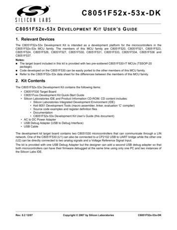
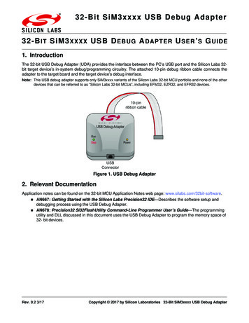
32-Bit SiM3xxxx USB Debug Adapter32-B IT SiM3 XXXX USB D E B U G A DAPTER U SER ’ S G UIDE1. IntroductionThe 32-bit USB Debug Adapter (UDA) provides the interface between the PC’s USB port and the Silicon Labs 32bit target device’s in-system debug/programming circuitry. The attached 10-pin debug ribbon cable connects theadapter to the target board and the target device’s debug interface.Note: This USB debug adapter supports only SiM3xxxx variants of the Silicon Labs 32-bit MCU portfolio and none of the otherdevices that can be referred to as “Silicon Labs 32-bit MCUs”, including EFM32, EZR32, and EFR32 devices.Figure 1. USB Debug Adapter2. Relevant DocumentationApplication notes can be found on the 32-bit MCU Application Notes web page: www.silabs.com/32bit-software. AN667:Getting Started with the Silicon Labs Precision32 IDE—Describes the software setup anddebugging process using the USB Debug Adapter. AN678: Precision32 Si32FlashUtility Command-Line Programmer User’s Guide—The programmingutility and DLL discussed in this document uses the USB Debug Adapter to program the memory space of32- bit devices.Rev. 0.2 3/17Copyright 2017 by Silicon Laboratories 32-Bit SiM3xxxx USB Debug Adapter
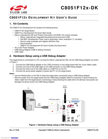
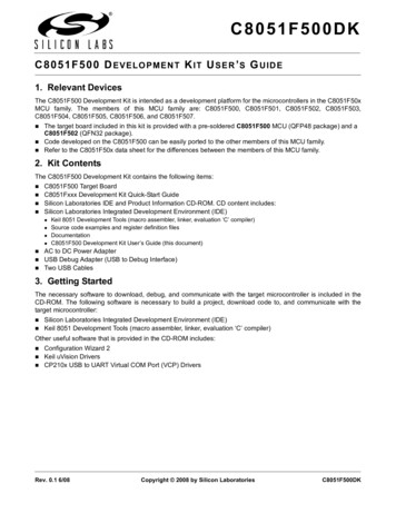
32-Bit SiM3xxxx USB Debug Adapter3. Pinout SpecificationThe 32-Bit USB Debug Adapter supports both JTAG and Serial Wire debug interfaces, and the adapter is poweredfrom the USB connection to the PC. The adapter uses the standard ARM CoreSight 10-pin connector. Table 1shows the pin definitions for the UDA keyed connector. The part number for the matching shrouded and keyed connector for a PCB is FTSH-105-01-F-F-K from Samtec. More information on the CoreSight connectors can be foundhere: http://www.keil.com/coresight/connectors.asp.The USB Debug Adapter can automatically change the communication voltage level based on the level detectedon pin 1 of the connector.Note: The USB Debug Adapter requires a target system clock of 4 kHz or greater.Table 1. USB Debug Adapter Debug Connector Pin DescriptionsPin #DescriptionDetails1VREFThis is the I/O reference voltage and shouldnormally be connected to the I/O voltage on thedevice (VIO, or VDD on devices without VIO).2SWDIO / TMSSerial Wire Data I/O or JTAG TMS3GND (Ground)4SWCLK / TCK5GND (Ground)6SWO / TDO7Not Connected8TDI9GND (Ground)10RESETBSerial Wire Clock or JTAG TCKSerial Wire Output (for Serial Wire Viewer orSWV) or JTAG TDOJTAG TDIThis pin should be connected to the RESETBpin of the device.1 3 5 7 92 4 6 8 10Figure 2. 32-Bit USB Debug Adapter Connector2Rev. 0.2
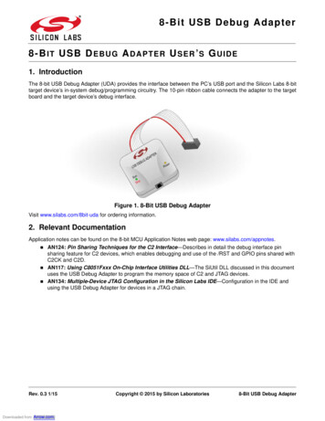
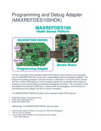
32-Bit SiM3xxxx USB Debug Adapter4. Minimum C2 Programming ConnectionsThe minimum required programming connections for the Serial Wire interface are VREF (pin 1), SWDIO (pin 2),SWCLK (pin 4), and ground (pins 3, 5, or 9). RESETB (pin 10) is highly recommended for debugging purposes, butis not required for production programming.5. Hardware Setup using a USB Debug AdapterConnect a 32-bit target board to a PC running the Silicon Laboratories Precision32 IDE via the USB DebugAdapter as shown in Figure 3.1. Connect the USB Debug Adapter’s 10-pin ribbon cable to the 10-pin CoreSight connector on the targetboard.2. Connect one end of a standard USB cable to the USB connector on the USB Debug Adapter.3. Connect the other end of the USB cable to a USB Port on the PC.4. Power the target board.Notes: Use the Reset / Restart button in the IDE to reset the target when connected using a USB Debug Adapter. Remove power from the target board and the USB Debug Adapter before connecting or disconnecting theribbon cable from the target board. Connecting or disconnecting the cable when the devices have power candamage the device and/or the USB Debug Adapter.132Figure 3. Hardware Setup using a USB Debug Adapter6. USB DriversThe USB Debug Adapter uses the Human Interface Device (HID) USB interface to communicate with the PC.Since most operating systems have this driver automatically built in, no drivers need to be installed to use the UDA.Rev. 0.23
32-Bit SiM3xxxx USB Debug Adapter7. Software Setup using a USB Debug AdapterThe Silicon Laboratories Precision32 IDE along with other software tools are provided for device development anddebugging. The IDE is available for download from the Silicon Laboratories website (www.silabs.com/mcudownloads) and is also available on microcontroller development kit CD-ROMs.7.1. Configuring the USB Debug Adapter in the Precision32 IDEThe IDE will automatically detect and use any UDAs connected to the PC when a Debug session starts. Noadditional configuration is required. If the IDE does not detect the UDA, ensure the adapter is enumerated inDevice Manager as an HID device, it’s connected to the target board, and the target device is powered.4Rev. 0.2
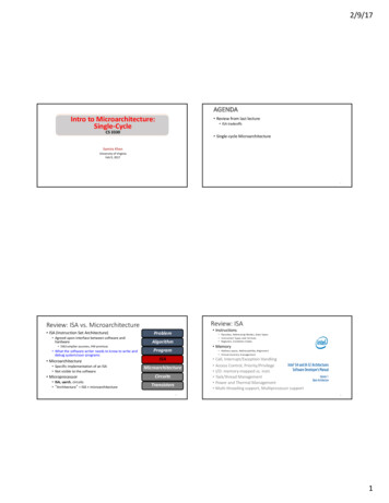
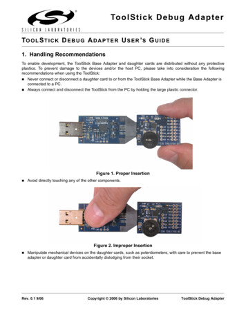
Figure 4. 32-Bit USB Debug Adapter Schematic (UDA-32) (page 1 of 2)32-Bit SiM3xxxx USB Debug Adapter8. SchematicsRev. 0.25
Figure 5. 32-Bit USB Debug Adapter Schematic (UDA-32) (page 2 of 2)32-Bit SiM3xxxx USB Debug Adapter6Rev. 0.2
Simplicity StudioOne-click access to MCU andwireless tools, documentation,software, source code libraries &more. Available for Windows,Mac and Linux!IoT Portfoliowww.silabs.com/IoTSW/HWQualitySupport and ualitycommunity.silabs.comDisclaimerSilicon Labs intends to provide customers with the latest, accurate, and in-depth documentation of all peripherals and modules available for system and software implementers using orintending to use the Silicon Labs products. Characterization data, available modules and peripherals, memory sizes and memory addresses refer to each specific device, and "Typical"parameters provided can and do vary in different applications. Application examples described herein are for illustrative purposes only. Silicon Labs reserves the right to make changeswithout further notice and limitation to product information, specifications, and descriptions herein, and does not give warranties as to the accuracy or completeness of the includedinformation. Silicon Labs shall have no liability for the consequences of use of the information supplied herein. This document does not imply or express copyright licenses grantedhereunder to design or fabricate any integrated circuits. The products are not designed or authorized to be used within any Life Support System without the specific written consent ofSilicon Labs. A "Life Support System" is any product or system intended to support or sustain life and/or health, which, if it fails, can be reasonably expected to result in significant personalinjury or death. Silicon Labs products are not designed or authorized for military applications. Silicon Labs products shall under no circumstances be used in weapons of massdestruction including (but not limited to) nuclear, biological or chemical weapons, or missiles capable of delivering such weapons.Trademark InformationSilicon Laboratories Inc. , Silicon Laboratories , Silicon Labs , SiLabs and the Silicon Labs logo , Bluegiga , Bluegiga Logo , Clockbuilder , CMEMS , DSPLL , EFM , EFM32 ,EFR, Ember , Energy Micro, Energy Micro logo and combinations thereof, "the world’s most energy friendly microcontrollers", Ember , EZLink , EZRadio , EZRadioPRO ,Gecko , ISOmodem , Precision32 , ProSLIC , Simplicity Studio , SiPHY , Telegesis, the Telegesis Logo , USBXpress and others are trademarks or registered trademarks of SiliconLabs. ARM, CORTEX, Cortex-M3 and THUMB are trademarks or registered trademarks of ARM Holdings. Keil is a registered trademark of ARM Limited. All other products or brandnames mentioned herein are trademarks of their respective holders.Silicon Laboratories Inc.400 West Cesar ChavezAustin, TX 78701USAhttp://www.silabs.com
The 32-Bit USB Debug Adapter supports both JTAG and Serial Wire debug interfaces, and the adapter is powered from the USB connection to the PC. The adapter uses the standard ARM CoreSight 10-pin connector. Table 1 shows the pin definitions for the UDA keyed connector. The part number for the matching shrouded and keyed con-