Transcription
FACTORY AUTOMATIONAS-INTERFACEMAINTENANCE ANDTROUBLESHOOTING GUIDE
Table of ContentsAS-Interface Basics. 3Addressing Modules. 4Handheld Programmer(Reading Inputs and Settings Outputs). 5Gateway Quick Start. 6Gateway Advanced Features. 7Exchanging SafetyNodes. 8Exchanging SafetyMonitors. 9LED Functionality (Modules). 10LED Functionality (SafetyMonitors). 11Repeaters. 12Terminator and Tuner. 13Power Supplies. 14Analyzer. 152Subject to modifications without noticeCopyright Pepperl Fuchswww.pepperl-fuchs.com
As-Interface Basics Use only certified modules, gateways/scanners, and power supplies. Total segment cable length is 100 m. (See page 12.) This includes thetotal of all trunk and drop lines. One AS-Interface power supply is required per segment. Forexample, a network with 2 repeaters requires 3 power supplies. Exactly one gateway/scanner is required per network. 31 addresses maximum; extended addressing, 1-31a and 1-31b, ispermitted on 2.1 and 3.0 spec. networks for a total of 62 nodes. Address 0 (the factory default address) is used for automaticaddressing and is not permitted on a running system. Modules with extended addressing and 4-in/4-out are permitted onlyon networks where an M4 (3.0) master is used. Update time per module is 150 µs. The formula for scan time is150 μs x (number of addresses 2)- Single addresses require 1 scan- Dual addresses (a and b) require 2 scans-D ual addresses (a and b) 3.0 4-in/4-out require 2 scans for inputsand 4 scans for outputs- Analog modules (2.1) require 7 scans per point- Analog modules (3.0) require 3 or 4 scans per point Network cable can be run in any topology. No shield or termination is required. Specification-compliant flat or round cable must be used. Do not ground either AS-i or – under any circumstances anywhereon the network (ground fault). The network has a differentialcommunication signal.Subject to modifications without noticeCopyright Pepperl Fuchswww.pepperl-fuchs.com3
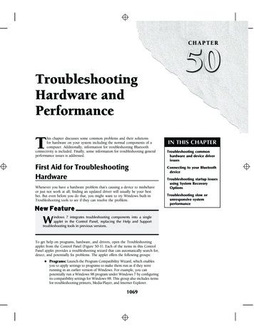
Addressing Modules If only one module has failed: remove failed module connect new moduleAs long as the new module is identical (i.e., has the same I/O andID codes and has address 0 before connection), no additional stepsare necessary. If more than one module has failed: remove all failed modules use handheld programmer VBP-HH1 to manually assignaddresses to all but one replacement module the last replacement module will receive its address automaticallyNote: The VAZ-PK-1.5M-V1-G addressing cable is required to workwith any module using an addressing jack.Setting an Address Using Handheld Programmer1. Connect the module to the handheld usingeither the addressing cable, M12 receptacle, ordirect connection.2. Press the “ADR” button to display the currentaddress of the module3. Use arrow “ ” buttons to choose newaddress4. Press “PRG” button to set selected address5. Press “ADR” button to confirm addressThe diagnostic LEDs on the gateway/scannerindicate a fault when one or more modules aremissing or are not properly connected to network.4Subject to modifications without noticeCopyright Pepperl Fuchswww.pepperl-fuchs.comEMODPRGADR
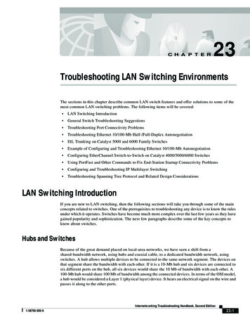
Handheld ProgrammerThe handheld programmer is a diagnostic tool that is used to read theinputs or set the outputs on a module. This is often done to isolate andtroubleshoot a specific I/O point.Procedure to Read Inputs and Set Outputs Make sure the handheld is in ADDR mode. Thisallows the address to be read. Press the “MODE”button until the ADDR mode is selected. Press “ADR” button and verify address is not zero.(If zero, see previous page to set valid address.) Change mode to DATA by pressing the “MODE”button 4x or 7x depending on module type. (Menuwill repeat if you go to far.)MOD Use arrow “ ” buttons to select output valueEPRG Press and hold “PRG” button to turn outputs onADR Press and hold “ADR” button to read inputsNote: T he chart below shows which inputs or outputsare activated when the hexadecimal digit is displayed.DisplayInputsOutputs01234567noneI1I2I1, I2I3I1, I3I2, I3I1, I2, I3noneO1O2O1, O2O3O1, O3O2, O3O1, O2, O3DisplayInputsOutputs89AbcdEI4I4, I1I4, I2I4, I2, I1I4, I3O4O4, O1I4, I3, I1 I4, I3, I2FI4, I3, I2, I1O4, O2 O4, O2, O1 O4, O3 O4, O3, O1 O4, O3, O2 O4, O3, O2, O1Subject to modifications without noticeCopyright Pepperl Fuchswww.pepperl-fuchs.com5
Gateway Quick StartWhen modules are added or removed from the network, the gatewaydetects this and indicates a “Config Error.” For gateways with a graphicaldisplay, use the following procedure to make the detected configuration(i.e., all modules found on the network) the active configuration.Config Error LED ONPress OK.5WARNING:OUTPUTS MAY BERESETPress OKPress OKPress Press DEVICENETQUICK SETUPSETUPIO PARAM. TESTPress OKSTORE AS-ICONFIGURATIONOKSTORE PRJ MODESTORE AS-ICONFIGURATIONSTORE RUNSTORE PRJ MODEPress ESC twiceConfig Error LED OFF.CONFIGURATION OKGateway LED FuctionalityLEDPowerConfig ErrorU AS-i6IndicationMeaningOn (Green)Power onOn (Red)One slave missing or extra slave on the networkFlashing (Red)Peripheral fault on networkOn (Green)AS-i network is sufficiently poweredAS-i ActiveOn (Green)AS-i network operating normally in either configuration orprotected modePRG EnableOn (Green)Exactly one slave is missing in protected operating modeand automatic addressing is allowedPRJ ModeOn (Yellow)AS-i master is in configuration modeSubject to modifications without noticeCopyright Pepperl Fuchswww.pepperl-fuchs.com
Gateway Advanced FeaturesSome gateways have advanced diagnosticfeatures that can assist in finding networkproblems. The built-in fault detector will displaynew and old network errors. All advanceddiagnostics are found on the display by going toADV. DIAGNOSIS AS-I CIRCUIT x .UPOWEMN RSCONFIGAS ER-i RAS-i APR CTIVGEENPR AJ M BLEODERS 232Error Counters If a node requires at least 2 consecutive retries,counts will appear on the display next to thatnode address. A clean network will have fewor no retries. Single retries are automaticallyhandled at the AS-Interface chip level andcannot be detected using the gateway. (Countsalways go up by 2.) If any node has 6 consecutive retries, it appearsin the LCS with an X by the node address. (Thisnode caused a configuration error.)Fault DetectorThe following errors occurred in the past (HISTORIC)or are currently happening (ACTUAL). Duplicateaddresses are also displayed on this screen.EFLT: An earth or ground fault has occurred.Check to make sure that AS-i or - is nottouching machine ground anywhere.OVRV: A power spike occurred on AS-i such thatthe AS-i voltage was too high.ESC ASI-ModeSetOKASI ASI- PWR- NC NCERROR COUNTERSRESET1A - 02A - 0RESETAPF 2A 4A - xIII1A - x3A 5A -FAULT DETECTORRESETHISTORIC:EFLT OVRV NOISACTUAL:EFLT OVRV NOISDUP ASI ADR:0I31BHELP:EFLT EARTH FAULTNOIS NOISEDUP ASI ADRDUPLICATE ASISLAVE ADDRESSNOIS: Noise was detected. Route AS-i cable awayfrom potential noise sources.Subject to modifications without noticeCopyright Pepperl Fuchswww.pepperl-fuchs.com7
Exchanging SafetyNodesCompared to standard modules, exchanging a SafetyNode requires a fewadditional steps. See procedure for single and multiple node replacement.Exchanging a Single Failed SafetyNode1. Remove SafetyNode.2. Lightly press the “Service” button on all affected SafetyMonitors.LEDs 1, 2, and 3 will cycle slowly on the SafetyMonitor.3. Connect replacement SafetyNode, make sure it receives an AS-iaddress and its inputs are closed so that full safety-code sequencesare received by the SafetyMonitor.4. Press the “Service” button on all affected SafetyMonitors. If successful,LEDs 1, 2, 3 will turn off and the SafetyMonitor will start normally.Exchanging Multiple Failed SafetyNodes1. Remove all defective SafetyNodes.2. Use handheld programmer VPB-HH1 to manually assign all addresses.(See page 4.) Confirm there is no configuration error on gateway/scanner. (Make sure all e-stops are pressed, all gates are open, and alllight curtains are broken such that S1 and S2 safety input LEDs are offon all recently replaced SafetyNodes.)3. The safety sequence must now be taught by following the procedurein “Exchanging a Single Failed SafetyNode.” Repeat this procedure forevery recently replaced SafetyNode on the network.ATTENTION! After replacing the defective SafetyNodes, makecertain to check the new modules for correct functionality.8Subject to modifications without noticeCopyright Pepperl Fuchswww.pepperl-fuchs.com
Exchanging SafetyMonitors1. Disconnect the failed SafetyMonitor from the 24 VDC power supply.Both L and M must be removed!2. Use the special download cable, VAZ-SIMON-RJ45. Connect thenew and old SafetyMonitors together.ServiceServiceRemovableterminalrelease tabsThe replacement SafetyMonitor must be new with no configurationor have a configuration that is not validated.3. Power up replacement SafetyMonitor by connecting both L and M.4. Press the “Service” button on replacement SafetyMonitor.On the replacement SafetyMonitor, active transmission is indicatedwhen the yellow READY LED is illuminated. Transfer is completewhen the GREEN and YELLOW LEDs are both lit.5. Disconnect defective SafetyMonitor and move all cables toreplacement SafetyMonitor. (Version 2.14 has keyed removableterminals. Press the release tab in at the top of the monitor and pullterminals straight up to remove.)Subject to modifications without noticeCopyright Pepperl Fuchswww.pepperl-fuchs.com9
Led Functionality (Modules)IN1IN2O1 nOOut10IndicationMeaningOffNo powerOn (Green)NormalFlashing (Green)Address 0 (FAULT LED on) or peripheral fault (FAULTLED flashing)OffNormalOn (Red)No AS-i communication; check addressFlashing (Red)Peripheral fault; check I/OOffNo powerOn (Green)NormalOn (Red)No AS-i communication; check addressAlternating (Red/Yellow)Address 0Alternating (Red/Green)Peripheral fault; check I/OOFFNo AUX power; check black AS-Interface cableONNormalOFFInput OFF; no AUX power or wire brokenONInput ONOFFOutput OFF; no AUX power or output not set by PLCONOutput ONONOutput shorted/overloaded (if supported by module)Subject to modifications without noticeCopyright Pepperl Fuchswww.pepperl-fuchs.com
LED Functionality (SafetyMonitors)not usedLED AS-i 1ServiceLED AS-i 2Output circuit 1LEDAS-iIndication1231 READY2 ON3 OFF/FAULT123Output circuit 2(on dual channel units only)MeaningOffNo 30 V AS-i connection to AS-i and AS-i- terminalsOn (Green)NormalOffNormal operationOn (Red)No AS-i communication or monitor address not stored ingateway/scannerOn (Yellow)Waiting for start condition or door unlock conditionFlashing (Yellow)Safety module test, local acknowledge required, ordiagnostic stop enabledOn (Green)Contacts of the output switching elements closedFlashing (Green)Delay time runs in event of Stop Category 1On (Red)Contacts of the output switching elements openFlashing (Red)Error on level of the monitored AS-i components1 READY2 ON3 OFF/FAULTSimultaneouslyflashing rapidlyInternal device error; power cycle is required1 READY2 ON3 OFF/FAULTCycling slowlyLearning safety code sequences1 READY2 ON3 OFF/FAULTOffNo 24 V supply connected to L and M terminalsAS-i 1AS-i 21 READY2 ON3 OFF/FAULTSubject to modifications without noticeCopyright Pepperl Fuchswww.pepperl-fuchs.com11
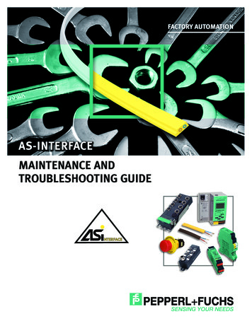
RepeatersThe communication path between an AS-i module and gateway/scanner must not go through more then 2 repeaters. This exampleshows a network with 5 segments, 4 repeaters and a total length of500 m. Note the position of the gateway in the middle segment.AS-InterfacePower SupplyAS-InterfacePower SupplyAS-InterfacePower SupplyAS-InterfaceScanner/GatewayI/OModule100 m total cable lengthI/OModule100 m total cable length30 mI/OModule100 m total cable length30 m30 m30 m20 mAS-InterfacePower Supply20 m30 m20 m20 mRepeater20 m30 m20 m20 mRepeater5mRepeater20 m20 m30 m30 mRepeater20 m30 mI/OModule25 mI/OModuleAS-InterfacePower SupplyI/OModule100 m total cable lengthI/OModule100 m total cable lengthPWRFAULTOffMeaning122AS-Interfacesegment 2No power supply connectedOn (Green) NormalOffNormalOn (Red)No communicationA network that is properly setup will have: FLT2PWRIndicationPWLEDRFL 1T1A repeater adds a second galvanically isolated segment to the AS-inetwork. Because only communication passes through the repeatera second power supply is required. Never put more than one powersupply on a segment!AS-Interfacesegment 1One gateway/scannerOne power supply per segmentNo segment with more than 100 m total cable lengthNo module separated from the gateway/scanner by more than 2repeatersSubject to modifications without noticeCopyright Pepperl Fuchswww.pepperl-fuchs.com
Terminator and TunerThe fixed terminator, VAZ-TERM, extends the network to 200 m, and thetuner, VAZ-TUNER, extends the AS-i network to 300 m. These devices,however, will not correct problems caused by noise or bad AS-i cable.Requirements for installation The best network to extend is linear. A network that has manydrops/branches may not be extendable. The power supply must be located at one end of the networksegment and the terminator/tuner at the other end. If a repeater is to be used an “Advanced” repeater is required. Theadvanced repeaters VAR-G4F or VAR-KE3-TERM (with terminationswitch built in) have a faster response time, which is required tocouple long segments together. Always use analyzer VAZ-ANALYZER to verify network integrity.Tuning procedureGateway/scanner:1. Put in configuration mode byholding “mode” button for5 seconds.Tuner:1. Rotate “mode” switch to 2(tuning)2. Press “set” button untilLEDs strobe red, yellow,green, red.Tuner LED IndicationLEDIndicationErrorOn (Red)MeaningWarningOn (Yellow) 1% to 5% retriesGreenOn (Green) Less than 1% retriesGreater than 5% retriesTerminator LED IndicationIndicationOffMeaningNo power or voltage below 18.5 VOn (Yellow) Voltage above 18.5 VOn (Green) Voltage above 26 V4. When strobing stops (thismay take several minutes), rotate “mode” switch to 3 (run)Subject to modifications without noticeCopyright Pepperl Fuchswww.pepperl-fuchs.com13
Power Supplies Exactly one AS-Interface power supply is required for each segment. Only one ground/earth fault detection circuit should be used in eachsegment. This circuit could be on the power supply, gateway, orSafetyMonitor. Some gateways have duplicate address detection. To operate, thepower supply must be connected directly to the dedicated terminal(labeled PWR-) on the gateway.Power supplies withground fault detectionFloating EFD outputPENLAttach standard ACinput voltage here13 14 GND - -115/230 V switch(Only on K24 supply)VAN-115/230AC-K21-EFDLED Power (Green)DC OKEFDResetLED Overload (Red)EFD int.EFD ext.DeviceNet connectorAS-i 1 V (Red)2 CAN H AS-i(White) 3 Shield4 CAN L (Blue)Ground5 V- (Black)POWEMN RSCONFU IG EAS R-i RAS-i APR CTIVGEEPR NAJ M BLEODERS 232DeviceNet connector12345Connect AS-i segment here(Connect Ground terminal to machineground and the shield of AS-i cable if used)V (Red)CAN H (White)ShieldCAN L (Blue)V- (Black)L –Connect to AS-i segment here(Connect Ground terminal tomachine ground and the shieldof AS-i cable if used)Power OK (Green)Ground fault indication LED (Red)Reset button:press 1 s simulates ground fault, 2 s to reset ground faultRS press232POWEMN RSCONFU IG EAS R-i RAS-i APR CTIVGEEPR NAJ M BLEODEStandard powersupply wiringInternal/external ground fault switch:EFD int. – shuts off on ground fault,use pushbutton to resetEFT ext. – automatically recoversfrom ground fault (default)NDisplayDisplayAttach standard AC input voltage herePower supply connection for gatewaysESCGround ASI-AS-i Network14ModeSetOKESCASI ASI- PWR- NC NCGroundAS-i Power SupplySubject to modifications without noticeCopyright Pepperl Fuchswww.pepperl-fuchs.comModeSetOKASI1ASI2 ASI- PWR- ASI2- PWR-AS-i Network 1AS-i Network 1Power SupplyAS-i Network 2Power SupplyAS-i Network 2
AnalyzerThe network analyzer, VAZ-ANALYSER, provides information aboutnetwork stability and allows detailed analysis of protocol-specificcommunication detail.There are two modes of operation. The first is online statistics wherethe overall health of the network is read. The second is trace modewhere individual AS-i telegrams are recorded, filtered, and viewed forlater analysis. This mode is often used to track down specific input,output or timing problems.Online StatisticsAdvance statistics (check for)- Little or no missing telegrams- No slave telegrams withoutmaster callConsecutive errors- Make sure consecutiveerrors are kept toa minimum. (6x configuration error)Network overview- Check to make sure allconnected nodes aregreenI/O data- Verify that the input and output data is correct- Find out if a certain input is flickering or turning on for a short time byrunning a trace on that inputSubject to modifications without noticeCopyright Pepperl Fuchswww.pepperl-fuchs.com15
ContactPepperl Fuchs Inc.1600 Enterprise ParkwayTwinsburg, Ohio 44087 · USATel. 1 330 486-0001 · Fax 1 330 405-4710E-mail: fa-info@us.pepperl-fuchs.comWorldwide HeadquartersPepperl Fuchs GmbH · Mannheim · GermanyE-mail: fa-info@de.pepperl-fuchs.comUSA HeadquartersPepperl Fuchs Inc. · Twinsburg · USAE-mail: fa-info@us.pepperl-fuchs.comAsia Pacific HeadquartersPepperl Fuchs Pte Ltd · SingaporeCompany Registration no. 199003130EE-mail: ubject to modifications 2008 PEPPERL FUCHS, INC. Printed in USA Part No. 912040 09/08 00
www.pepperl-fuchs.com Subject to modifications without notice Copyright Pepperl Fuchs 7 Gateway Advanced Features Some gateways have advanced diagnostic